MITSUBISHI MONTERO 1987 1.G Workshop Manual
Manufacturer: MITSUBISHI, Model Year: 1987, Model line: MONTERO, Model: MITSUBISHI MONTERO 1987 1.GPages: 284, PDF Size: 14.74 MB
Page 241 of 284
HEATERS - Service Adjustment Procedures 24-5
SERVICE DJUSTMENT PROCEDURES
TEMPERATURE CONTROL SYSTEM ADJUST-
ENT
N24FAAD
MODE SELECTION LEVER
1. Move the mode selection lever to each position and check
the air flow with the blower operating.
2. If the air flow is not correct for any position of the mode
selection lever, adjust the mode selection control wire. If
this adjustment does not help, adjust the damper.
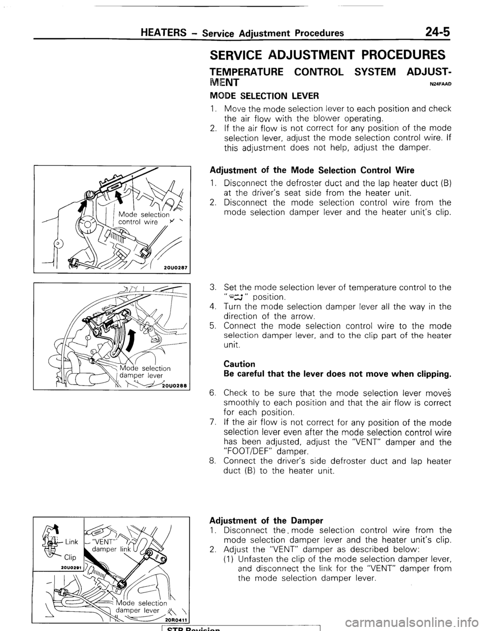
Adjustment of the Mode Selection Control Wire
1. Disconnect the defroster duct and the lap heater duct (B)
at the driver’s seat side from the heater unit.
2. Disconnect the mode selection control wire from the
mode selection damper lever and the heater unit,‘s clip.
3. Set the mode selection lever of temperature control to the
” ws ” position.
4. Turn the mode selection damper lever all the way in the
direction of the arrow.
5. Connect the mode selection control wire to the mode
selection damper lever, and to the clip part of the heater
unit.
Caution
Be careful that the lever does not move when clipping.
6. Check to be sure that the mode selection lever moves
smoothly to each position and that the air flow is correct
for each position.
7. If the air flow is not correct for any position of the mode
selection lever even after the mode selection control wire
has been adjusted, adjust the “VENT” damper and the
“FOOT/DEF” damper.
8. Connect the driver’s side defroster duct and lap heater
duct (B) to the heater unit.
Adjustment of the Damper
1. Disconnect the. mode selection control wire from the
mode selection damper lever and the heater unit’s clip.
2. Adjust the “VENT” damper as described below:
(1) Unfasten the clip of the mode selection damper lever,
and disconnect the link for the “VENT” damper from
the mode selection damper lever.
1 STB Revision
Page 242 of 284
24-6 HEATERS - Service Adjustment Procedures
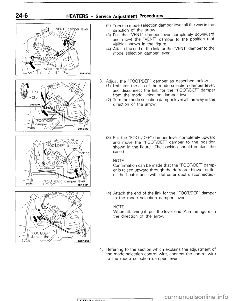
(2) Turn the mode selection damper lever all the way in the
direction of the arrow.
(3) Pull the “VENT” damper lever completely downward
and move the “VENT” damper to the position (not
visible) shown in the figure.
(4) Attach the end of the link for the “VENT” damper to the
: mode selection damper lever.
3. Adjust the “FOOT/DEF” damper as described below.
(1) Unfasten the clip of the mode selection damper lever,
and disconnect the link for the “FOOT/DEF” damper
from the mode selection damper lever.
(2) Turn the mode selection damper lever all the way in the
direction of the arrow.
(3) Pull the “FOOT/DEF” damper lever completely upward
and move the “FOOT/DEF” damper to the position
shown in the figure. (The packing should contact the
case.)
NOTE
Confirmation can be made that the “FOOT/DEF” damp-
er is raised upward through the defroster blower outlet
of the heater unit (with defroster duct disconnected).
(4) Attach the end of the link for the “FOOT/DEF” damper
to the mode selection damper lever.
NOTE
When attaching it, pull the lever end (A in the figure) in
the direction of the arrow.
4. Referring to the section which explains the adjustment of
the mode selection control wire, connect the control wire
to the mode selection damper lever.
1 STB Revision
Page 243 of 284
HEATERS - Service Adjustment Procedures 24-7
TEMPERATURE CONTROL LEVER
1. Move the temperature control lever from its extreme left
position to its extreme right position and check to be sure
that it moves correctly and smoothly to each position.
2. Then move the temperature control lever to the extreme
left position, and check to be sure that warm air does not
come out when the blower is operated.
3. If the air flow is not correct in the above step, adjust the
temperature control wire.
h?* I Water valve lever
-
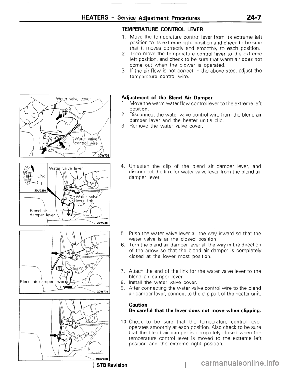
7 Blend air d Adjustment of the Blend Air Damper
I. Move the warm water flow control lever to the extreme left
position.
2. Disconnect the water valve control wire from the blend air
damper lever and the heater unit’s clip.
3. Remove the water valve cover.
4. Unfasten the clip of the blend air damper lever, and
disconnect the link for water valve lever from the blend air
damper lever.
5. Push the water valve lever all the way inward so that the
water valve is at the closed position.
6. Turn the blend air damper lever all the way in the direction
of the arrow so that the blend air damper is completely
closed at the lower most position.
7. Attach the end of the link for the water valve lever to the
blend air damper lever.
8. Install the water valve cover.
9. After connecting the water valve control wire to the blend
air damper lever, connect to the clip part of the heater unit. Caution
Be careful that the lever does not move when clipping.
10. Check to be sure that the temperature control lever
operates smoothly at each position. Also check to be sure
that the blend air damper is completely closed when the
temperature control lever is moved to the extreme left
position and the extreme right position. 1 STB Revision
Page 244 of 284
24-8 HEATERS - Service Adjustment Procedures
ater valve cover
2OW751
WAiER VALVE REPLACEMENT N24FBAC
I. Set the temperature control lever to the extreme right
position.
2. Remove the radiator drain plug, and then drain the engine
coolant.
3. Remove the air filter
4. Remove the heater hose clamp to disconnect the heater
hose.
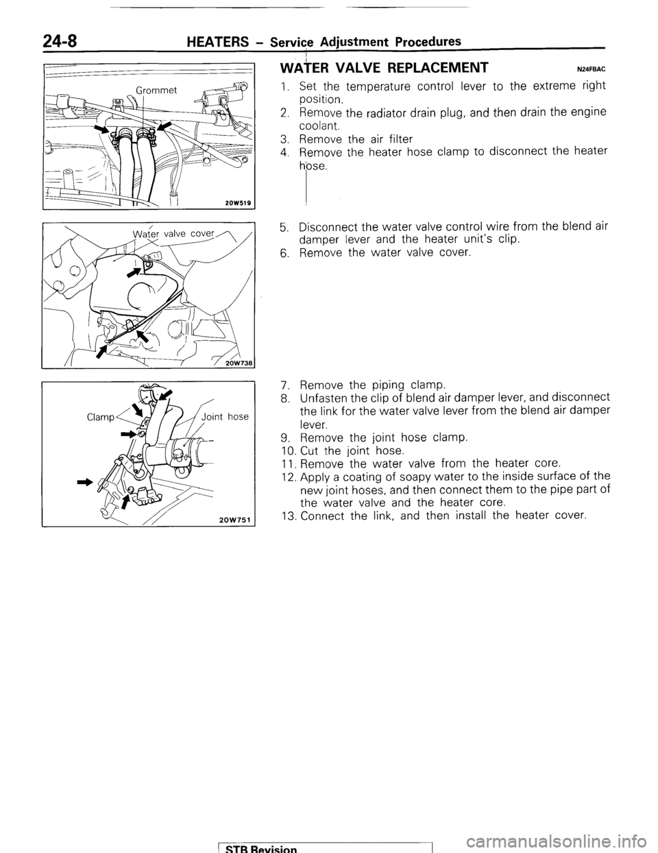
5. Disconnect the water valve control wire from the blend air
damper lever and the heater unit’s clip.
6. Remove the water valve cover.
7. Remove the piping clamp.
8. Unfasten the clip of blend air damper lever, and disconnect
the link for the water valve lever from the blend air damper
lever.
9. Remove the joint hose clamp.
10. Cut the joint hose.
11. Remove the water valve from the heater core.
12. Apply a coating of soapy water to the inside surface of the
new joint hoses, and then connect them to the pipe part of
the water valve and the heater core.
13. Connect the link, and then install the heater cover.
1 STB Revision
Page 245 of 284
HEATERS - Heater Control 24-9
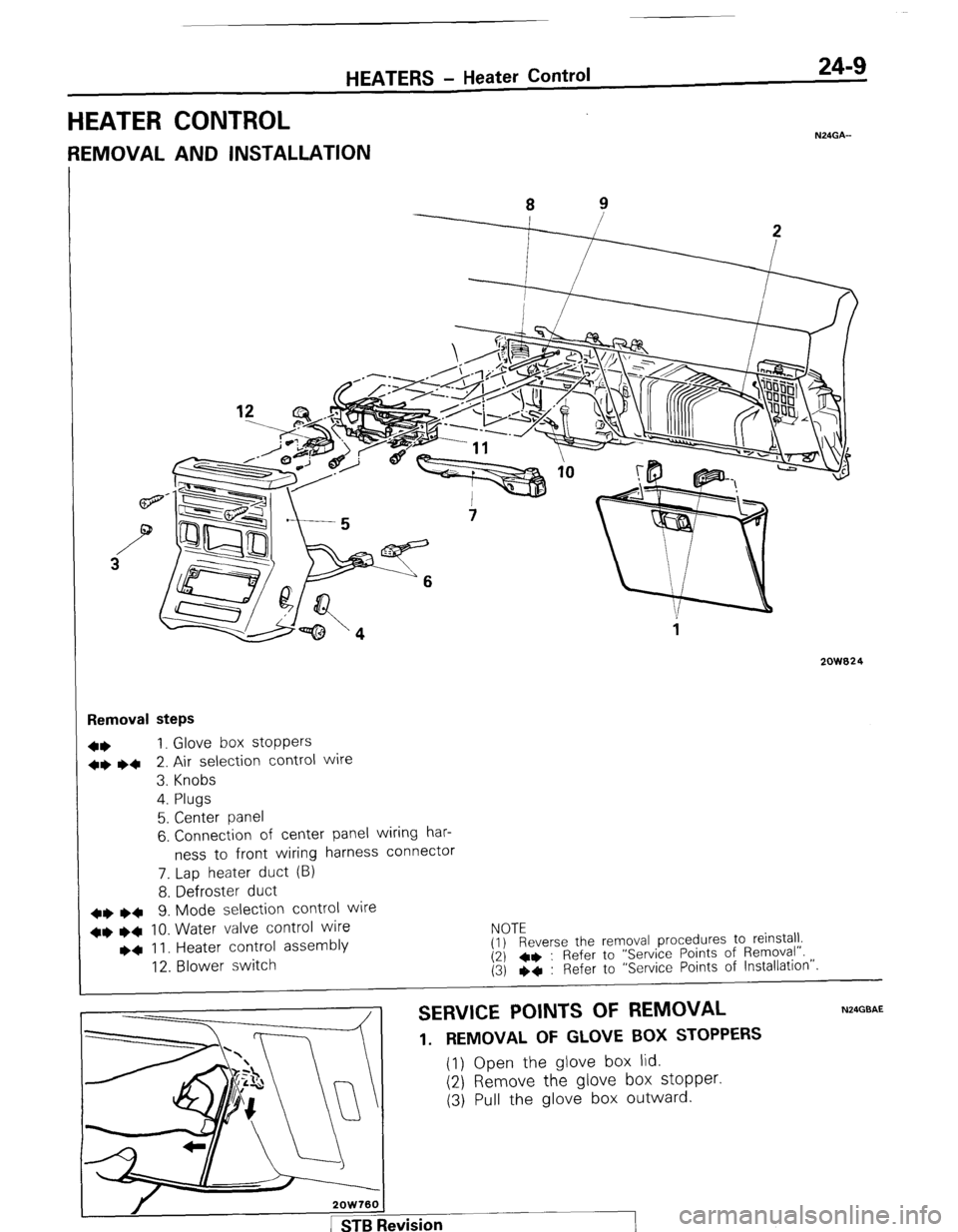
HEATER CONTROL
N24GA-
REMOVAL AND INSTALLATION
2QW824
Removal steps
4+ 1. Glove box stoppers
++ ~~ 2. Air selection control wire
3. Knobs
4. Plugs
5. Center panel
6. Connection of center panel wiring har-
ness to front wiring harness connector
7. Lap heater duct (B)
8. Defroster duct
++
l + 9. Mode selection control wire
++
l + 10. Water valve control wire
l a II. Heater control assembly
12. Blower switch EyTEeverse the removal procedures to reinstall.
(2) 4+ : Refer to “Service Points of Removal”.
(3) eq : Refer to “Service Points of Installation”.
SERVICE POINTS OF REMOVAL N24GBAE
1. REMOVAL OF GLOVE BOX STOPPERS (1) Open the glove box lid.
(2) Remove the glove box stopper. (3) Pull the glove box outward.
Page 246 of 284
24-10 HEATERS I- Heater Control
2ow7a7
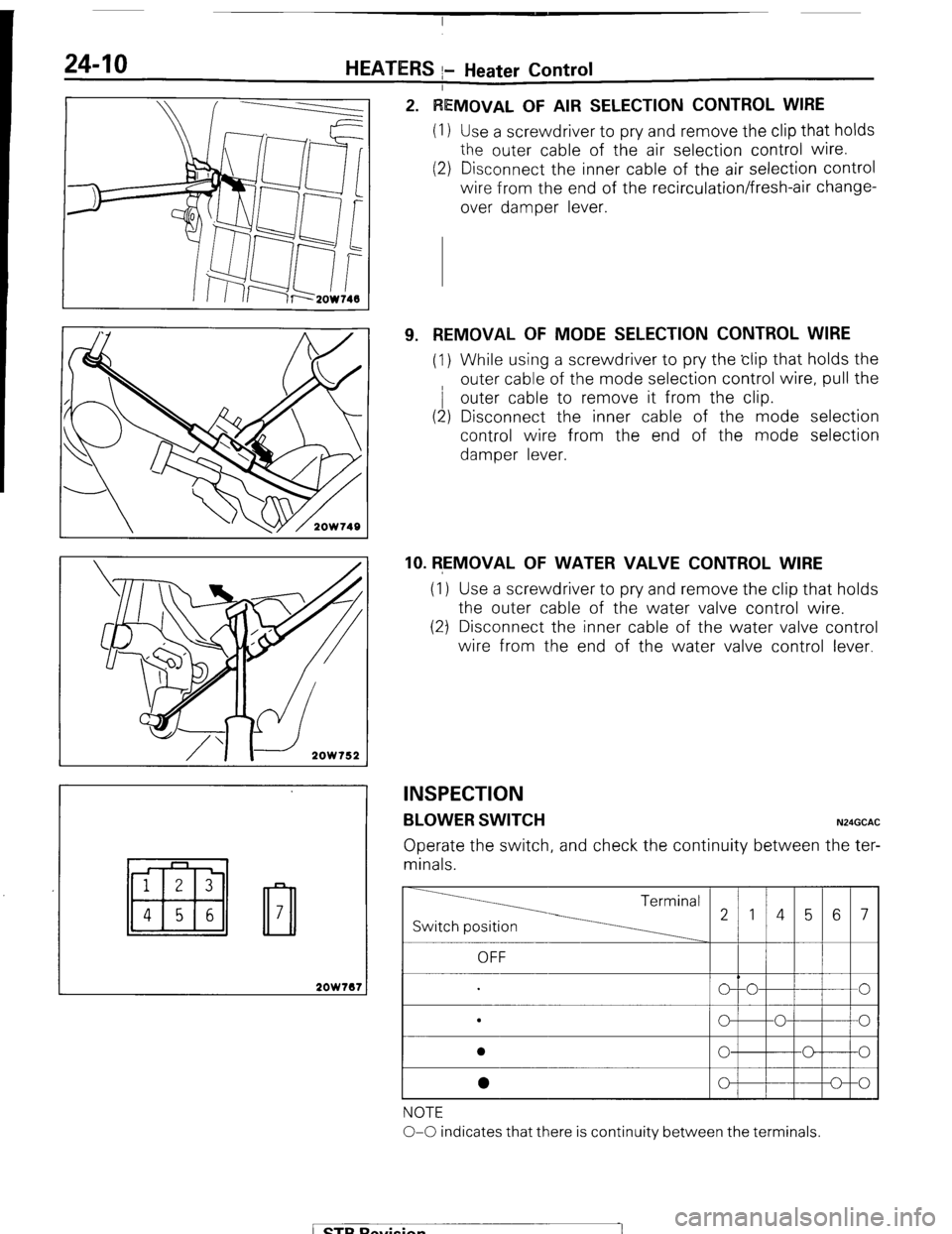
VIOVAL OF AIR SELECTION CONTROL WIRE
Use a screwdriver to pry and remove the clip that holds
the outer cable of the air selection control wire.
Disconnect the inner cable of the air selection control
wire from the end of the recirculation/fresh-air change-
over damper lever.
9. REMOVAL OF MODE SELECTION CONTROL WIRE
(1) While using a screwdriver to pry the clip that holds the
outer cable of the mode selection control wire, pull the
/ outer cable to remove it from the clip.
(2) Disconnect the inner cable of the mode selection
control wire from the end of the mode selection
damper lever.
10. REMOVAL OF WATER VALVE CONTROL WIRE
(1) Use a screwdriver to pry and remove the clip that holds
the outer cable of the water valve control wire.
(2) Disconnect the inner cable of the water valve control
wire from the end of the water valve control lever.
INSPECTION
BLOWER SWITCH N24GCAC
Operate the switch, and check the continuity between the ter-
minals.
Switch position
OFF
. Terminal
214567
o--O
0
0
0 0
NOTE
O-O indicates that there is continuity between the terminals.
/ STB Revision
-7
Page 247 of 284
HEATERS - Heater Control 24-11
Top view
Bottom view
I
2OW553
2OW534
2OW750
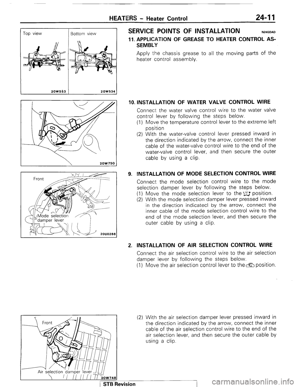
SERVICE POINTS OF INSTALLATION N24GDAD
11. APPLICATION OF GREASE TO HEATER CONTROL AS-
SEMBLY Apply the chassis grease to all the moving parts of the
heater control assembly.
10. lNSTALLATlON OF WATER VALVE CONTROL WIRE Connect the water valve control wire to the water valve
control lever by following the steps below.
(1) Move the temperature control lever to the extreme left
position
(2) With the water-valve control lever pressed inward in
the direction indicated by the arrow, connect the inner
cable of the water-valve control wire to the end of the
water-valve control lever, and then secure the outer
cable by using a clip.
9. INSTALLATION OF MODE SELECTION CONTROL WIRE Connect the mode selection control wire to the mode
selection damper lever by following the steps below.
(1) Move the mode selection lever to the %E position.
(2) With the mode selection damper lever pressed inward
in the direction indicatecl by the arrow, connect the
inner cable of the mode selection control wire to the
end of the mode selection lever, and then secure the
outer cable by using a clip.
2. INSTALLATION OF AIR SELECTION CONTROL WIRE Connect the air selection control wire to the air selection
damper lever by following the steps below.
(1) Move the air selection control lever to the& position.
(2) With the air selection damper lever pressed inward in
the direction indicated by the arrow, connect the inner
cable of the air selection control wire to the end of the
air selection lever, and then secure the outer cable by
using a clip.
1 STB Revision
Page 248 of 284
24-12 HEATERS - Heater Unit
I
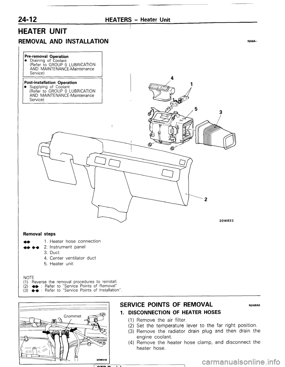
HEATER UNBT
REMOVAL AND INSTALLATION
Pre-removal Operation
0 Draining of Coolant
(Refer to GROUP 0 LUBRICATION
AND MAINTENANCE-Maintenance
Service)
Post-installation Operation
0 Supplying of Coolant
(Refer to GROUP 0 LUBRICATION
AND MAINTENANCE-Maintenance
Service) Removal steps
l *
I, Heater hose connection
+* l 4
2. Instrument panel
3. Duct
4. Center ventilator duct
5. Heater unit
NOTE
(1) Reverse the removal procedures to reinstall.
(2) +e : Refer to “Service Points of Removal”
(3) l
+ : Refer to “Service Points of Installation”
2OW823
SERVICE POINTS OF REMOVAL
1. DISCONNECTION OF HEATER HOSES (1) Remove the air filter.
(2) Set the temperature lever to the far
(3) Remove the radiator drain plug and
engine coolant.
(4) Remove the heater hose clamp, and
heater hose.
N24lBAE right position.
then drain the
disconnect the
ETB Revision
Page 249 of 284
HEATERS - Heater Unit 24-13
2. REMOVAL OF INSTRUMENT PANEL
Refer to GROUP 23 BODY-Instrument Panel.
INSPEGTION N24cAa
l
Check the damper and link mechanism for operation.
l Check the heater core for clogging or water leakage.
l Check the water valve for operation and clogging.
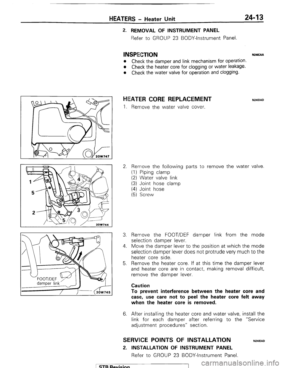
EATER CORE REPLACEMENT
I. Remove the water valve cover.
2. Remove the following parts to remove the water valve.
(1) Piping clamp
(2) Water valve link
(3) Joint hose clamp
(4) Joint hose
(5) Screw
3. Remove the FOOT/DEF damper link from the mode
selection damper lever.
4. Move the damper lever to the position at which the mode
selection damper lever does not protrude very much to the
heater core side.
5. Remove the heater core. If at this time the damper lever
and heater core are in contact, making removal difficult,
remove the damper lever.
Caution
To prevent interference between the heater
core and
case, use care not to peel the heater
core felt away
when the heater core is removed.
6. After installing the heater core and water valve, install the
link for each damper after referring to the “Service
adjustment procedures” section.
SERWOCE POINTS OF INSTALLATION
2. INSTALLATION OF INSTRUMENT PANEL
Refer to GROUP 23 BODY-Instrument Panel.
N241EAD
1 STB Revision
Page 250 of 284
24-14 HEATERS + Blower Assembly
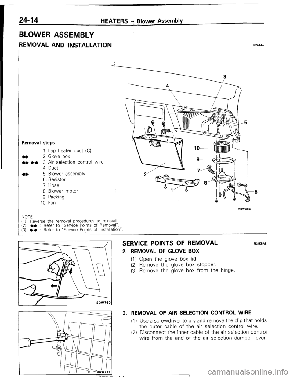
BLOWER ASSEMBLY
REMOVAL AND INSTALLATION NXKA-
Removal steps
1. Lap heater duct (C)
+* 2. Glove box
+e l + 3. Air selection control wire
4. Duct
4* 5. Blower assembly
6. Resistor
7. Hose
8. Blower motor
9. Packing
10. Fan
2oWBO6
6
NOTE
(1) Reverse the removal procedures to relnstall. (2) l * : Refer to “Service Points of Removal”.
(3) l * : Refer to “Service Points of Installation”.
SERVICE POINTS OF REMOVAL N24KBAE
2. REMOVAL OF GLOVE BOX
(1) Open the glove box lid.
(2) Remove the glove box stopper.
(3) Remove the glove box from the hinge.
3. REMOVAL OF AIR SELECTION CONTROL WIRE
(1) Use a screwdriver to pry and remove the clip that holds
the outer cable of the air selection control wire.
(2) Disconnect the inner cable of the air selection control
wire from the end of the air selection damper lever.