MITSUBISHI OUTLANDER SPORT 2014 3.G Owners Manual
Manufacturer: MITSUBISHI, Model Year: 2014, Model line: OUTLANDER SPORT, Model: MITSUBISHI OUTLANDER SPORT 2014 3.GPages: 388, PDF Size: 20.04 MB
Page 351 of 388
Tyres11-10 Maintenance
11
E01001402726
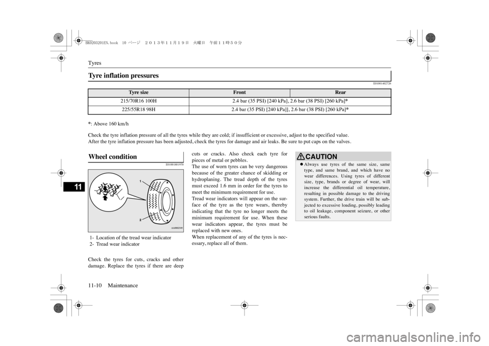
*: Above 160 km/hCheck the tyre inflation pressure of all the tyres while they ar
e cold; if insufficient or excessive, adjust to the specified v
alue.
After the tyre inflation pressure has been adjusted, check the tyres for damage and air leaks. Be sure to put caps on the valve
s.
E01001801970
Check the tyres for cuts, cracks and otherdamage. Replace the tyres if there are deep
cuts or cracks. Also check each tyre forpieces of metal or pebbles.The use of worn tyres can be very dangerousbecause of the greater chance of skidding orhydroplaning. The tread depth of the tyresmust exceed 1.6 mm in order for the tyres tomeet the minimum requirement for use.Tread wear indicators will appear on the sur-face of the tyre as the tyre wears, therebyindicating that the tyre no longer meets theminimum requirement for use. When thesewear indicators appear, the tyres must bereplaced with new ones.When replacement of any of the tyres is nec-essary, replace all of them.
Ty r e i n f l a t i o n p r e s s u r e s
Ty re s i z e
Front
Rear
215/70R16 100H
2.4 bar (35 PSI) [240 kPa], 2.6 bar (38 PSI) [260 kPa]
*
225/55R18 98H
2.4 bar (35 PSI) [240 kPa]], 2.6 bar (38 PSI) [260 kPa]
*
Wheel condition 1- Location of the tread wear indicator2- Tread wear indicator
CAUTION�zAlways use tyres of the same size, sametype, and same brand, and which have nowear differences. Using tyres of differentsize, type, brands or
degree of wear, will
increase the differential oil temperature,resulting in possible damage to the drivingsystem. Further, the drive train will be sub-jected to excessive loading, possibly leadingto oil leakage, component seizure, or otherserious faults.
BK0203201EN.book 10 ページ 2013年11月19日 火曜日 午前11時50分
Page 352 of 388
Tyres
Maintenance 11-11
11
E01007200243E01001902486
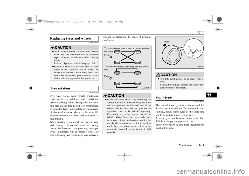
Ty r e w e a r v a r i e s w i t h v e h i c l e c o n d i t i o n s ,road surface conditions and individualdriver’s driving habits. To equalise the wearand help extend tyre life, it is recommendedto rotate the tyres immediately after discoveryof abnormal wear, or whenever the wear dif-ference between the front and rear tyres isrecognisable.When rotating tyres, check for uneven wearand damage. Abnormal wear is usuallycaused by incorrect tyre pressure, improperwheel alignment, out of balance wheel, orsevere braking. We recommend you to have it
checked to determine the cause of irregulartread wear.
E01002000754
The use of snow tyres is recommended fordriving on snow and ice. To preserve drivingstability, mount snow tyres of the same sizeand tread pattern on all four wheels.A snow tyre that is
worn down more than
50% is no longer appropriate to use.Snow tyres which do not meet specificationsmust not be used.
Replacing tyres and wheels
CAUTION�zAv o i d u s i n g d i f f e r e n t s i z e t y r e s f r o m t h e o n elisted and the combined
use of different
types of tyres, as th
is can affect driving
safety.Refer to “Tyres and wheels” on page 12-8.�zEven if a wheel has the same rim size andoffset as the specified type of wheel, itsshape may prevent it from being fitted cor-rectly. We recommend you to consult a spe-cialist before using wheels that you have.
Ty r e r o t a t i o n
CAUTION�zIf the tyres have arrows (A) indicating thecorrect direction of rotation, swap the frontand rear tyres on the left-hand side of thevehicle and the front and rear tyres on theright-hand side of th
e vehicle separately.
Keep each tyre on its original side of thevehicle. When fitting the tyres, make surethe arrows point in the direction in which thewheels will turn when the vehicle moves for-ward. Any tyre whose arrow points in thewrong direction will not perform to its fullpotential.Tyres that do not have arrows showing rotation directionFrontTy r e s t h a t h a v e a r r o w s s h o w i n g r o t a t i o n d i r e c -tionFront
CAUTION�zAvoid the combined use of different types oftyres.Using different types of
tyres can affect vehi-
cle performance and safety.
Snow tyres
Front
BK0203201EN.book 11 ページ 2013年11月19日 火曜日 午前11時50分
Page 353 of 388
Wiper blade rubber replacement11-12 Maintenance
11
E01002101882
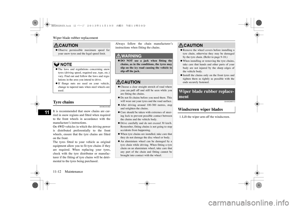
It is recommended that snow chains are car-ried in snow regions and fitted when requiredto the front wheels in accardance with themanufacture’s instructions.On 4WD vehicles in which the driving poweris distributed preferentially to the frontwheels, ensure that the tyre chains are fittedon the front.The tyres fitted to your vehicle as originalequipment allow you to fit tyre chains if theyare required. When replacing your tyres,check with the tyre distributor or manufac-turer if the fitting of tyre chains will be detri-mental to the tyres being purchased.
Always follow the chain manufacturer’sinstructions when fitting the chains.
E01002600532
1. Lift the wiper arm off the windscreen.
CAUTION�zObserve permissible maximum speed foryour snow tyres and the legal speed limit.NOTE
�zThe laws and regula
tions concerning snow
tyres (driving speed, requi
red use, type, etc.)
vary. Find out and follow the laws and regu-lations in the area you intend to drive.�zIf flange nuts are used on your vehicle,change to tapered nuts when steel wheels areused.
Ty r e c h a i n s
WA R N I N G�zDO NOT use a jack when fitting thechains, as in the conditions, the tyres mayslip on the ic
y road causing the vehicle to
slip off the jack.CAUTION�zChoose a clear straight stretch of road whereyou can pull off and still be seen while youare fitting the chains.�zDo not fit chains before you need them. Thiswill wear out your tyres and the road surface.�zAfter driving around 100-300 metres, stopand retighten the chains.�zCare should be taken with extremes of steer-ing lock to prevent possible contact betweenthe chains and the vehicle body.�zDrive carefully and do not exceed 30 km/h.Remember, fitting chains is not going to stopaccidents from happening.�zWhen tyre chains are installed, take care thatthey do not damage the disc wheel or body.�zAn aluminium wheel can be damaged by atyre chain while driving. When fitting a tyrechain on an aluminium wheel, take care thatany part of the chai
n and fitting cannot be
brought into contact with the wheel.
�zRemove the wheel covers before installing atyre chain, otherwise they may be damagedby the tyre chain. (Refer to page 9-18.)�zWhen installing or removing the tyre chains,take care that hands and other parts of yourbody are not injured by the sharp edges ofthe vehicle body.�zInstall the chains only on the front tyres andtighten them as tightly
as possible with the
ends securely fastened.
Wiper blade rubber replace-ment Windscreen wiper blades
CAUTION
BK0203201EN.book 12 ページ 2013年11月19日 火曜日 午前11時50分
Page 354 of 388
Wiper blade rubber replacement
Maintenance 11-13
11
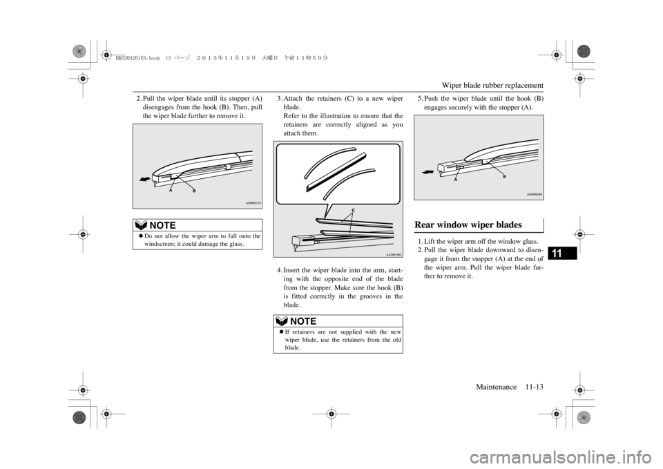
2. Pull the wiper blade until its stopper (A)disengages from the hook (B). Then, pullthe wiper blade further to remove it.
3. Attach the retainers (C) to a new wiperblade.Refer to the illustration to ensure that theretainers are correctly aligned as youattach them.4. Insert the wiper blade into the arm, start-ing with the opposite end of the bladefrom the stopper. Make sure the hook (B)is fitted correctly in the grooves in theblade.
5. Push the wiper blade until the hook (B)engages securely with the stopper (A).1. Lift the wiper arm off the window glass.2. Pull the wiper blade downward to disen-gage it from the stopper (A) at the end ofthe wiper arm. Pull the wiper blade fur-ther to remove it.
NOTE
�zDo not allow the wiper arm to fall onto thewindscreen; it coul
d damage the glass.
NOTE
�zIf retainers are not supplied with the newwiper blade, use the retainers from the oldblade.
Rear window wiper blades
BK0203201EN.book 13 ページ 2013年11月19日 火曜日 午前11時50分
Page 355 of 388
General maintenance11-14 Maintenance
11
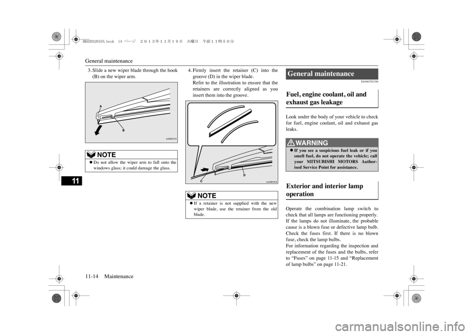
3. Slide a new wiper blade through the hook(B) on the wiper arm.
4. Firmly insert the retainer (C) into thegroove (D) in the wiper blade.Refer to the illustration to ensure that theretainers are correctly aligned as youinsert them into the groove.
E01002701556
Look under the body of your vehicle to checkfor fuel, engine coolant, oil and exhaust gasleaks.Operate the combination lamp switch tocheck that all lamps are functioning properly.If the lamps do not illuminate, the probablecause is a blown fuse or defective lamp bulb.Check the fuses first. If there is no blownfuse, check the lamp bulbs.For information regarding the inspection andreplacement of the fuses and the bulbs, referto “Fuses” on page 11-15 and “Replacementof lamp bulbs” on page 11-21.
NOTE
�zDo not allow the wiper arm to fall onto thewindows glass; it could damage the glass.
NOTE
�zIf a retainer is not supplied with the newwiper blade, use the retainer from the oldblade.
General maintenance Fuel, engine coolant, oil and exhaust gas leakage
WA R N I N G�zIf you see a suspicious
fuel leak or if you
smell fuel, do not operate the vehicle; callyour MITSUBISHI MOTORS Author-ised Service Point for assistance.
Exterior and interior lamp operation
BK0203201EN.book 14 ページ 2013年11月19日 火曜日 午前11時50分
Page 356 of 388
Fusible links
Maintenance 11-15
11
If the fuses and bulbs are all OK, we recom-mend you to have your vehicle checked andrepaired.Start the plug-in hybrid EV system and checkthe operation of all instruments, gauges andindicator and warning lamps.If there is anything wrong, we recommendyou to have your vehicle inspected.Check all latches and hinges, and, if neces-sary, have them lubricated.
E01002901633
The fusible links will melt to prevent a fire ifa large current attempts to flow through cer-tain electrical systems.In case of a melted fusible link, we recom-mend you to have your vehicle inspected.For the fusible links, please refer to “Passen-ger compartment fuse location table” on page11 -17 a nd “Engine co mpa rtment fuse loc a-tion table” on page 11-18.
E01003003332E01011800035
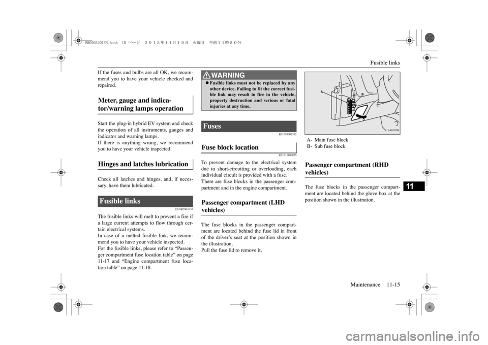
To p r e v e n t d a m a g e t o t h e e l e c t r i c a l s y s t e mdue to short-circuiting or overloading, eachindividual circuit is provided with a fuse.There are fuse blocks in the passenger com-partment and in the engine compartment.The fuse blocks in the passenger compart-ment are located behind the fuse lid in frontof the driver’s seat at the position shown inthe illustration.Pull the fuse lid to remove it.
The fuse blocks in the passenger compart-ment are located behind the glove box at theposition shown in the illustration.
Meter, gauge and indica-tor/warning lamps operation Hinges and latches lubrication Fusible links
WA R N I N G�zFusible links must not be replaced by anyother device. Failing to fit the correct fusi-ble link may result in fire in the vehicle,property destruction and serious or fatalinjuries at any time.
Fuses Fuse block location Passenger compartment (LHD vehicles)
A- Main fuse blockB- Sub fuse blockPassenger compartment (RHD vehicles)
BK0203201EN.book 15 ページ 2013年11月19日 火曜日 午前11時50分
Page 357 of 388
Fuses11-16 Maintenance
11
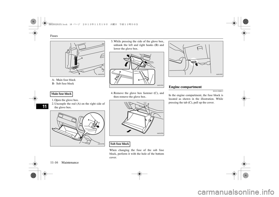
1. Open the glove box.2. Uncouple the rod (A) on the right side ofthe glove box.
3. While pressing the side of the glove box,unhook the left and right hooks (B) andlower the glove box.4. Remove the glove box fastener (C), andthen remove the glove box.
When changing the fuse of the sub fuseblock, perform it with the hole of the bottomcover.
E01011900023
In the engine compartment, the fuse block islocated as shown in the illustration. Whilepressing the tab (C), pull up the cover.
A- Main fuse blockB- Sub fuse blockMain fuse block
Sub fuse block
Engine compartment
BK0203201EN.book 16 ページ 2013年11月19日 火曜日 午前11時50分
Page 358 of 388
Fuses
Maintenance 11-17
11
E01007701753
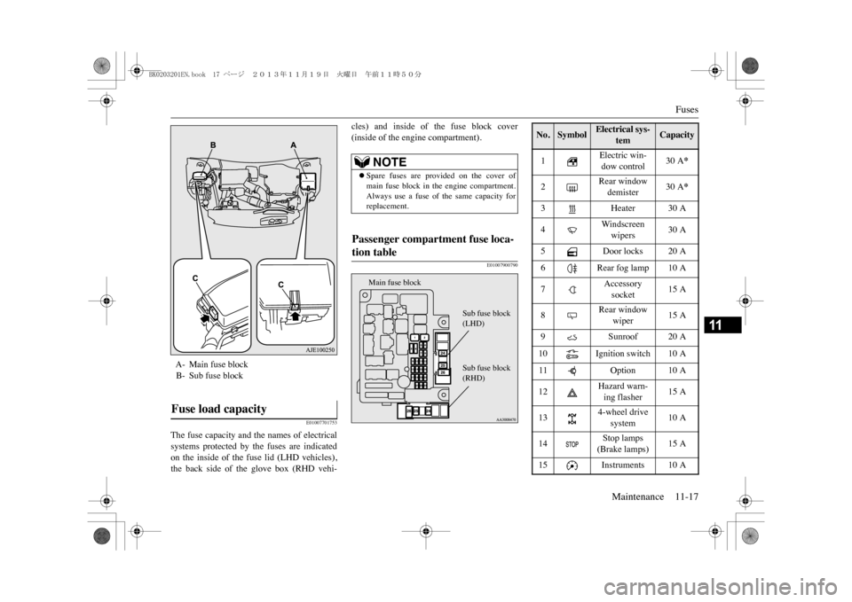
The fuse capacity and the names of electricalsystems protected by the fuses are indicatedon the inside of the fuse lid (LHD vehicles),the back side of the glove box (RHD vehi-
cles) and inside of the fuse block cover(inside of the engine compartment).
E01007900790
A- Main fuse blockB- Sub fuse blockFuse load capacity
NOTE
�zSpare fuses are provided on the cover ofmain fuse block in the engine compartment.Always use a fuse of the same capacity forreplacement.
Passenger compartment fuse loca-tion table
Main fuse block
Sub fuse block(LHD)Sub fuse block(RHD)
No.
Symbol
Electrical sys-
tem
Capacity
1
Electric win-dow control
30 A
*
2
Rear window demister
30 A
*
3 Heater 30
A
4
Wi n dsc reen wipers
30 A
5
Door locks 20 A
6
Rear fog lamp 10 A
7
Accessory socket
15 A
8
Rear window
wiper
15 A
9
Sunroof 20 A
10 Ignition
switch 10
A
11 Option 10
A
12
Hazard warn-ing flasher
15 A
13
4-wheel drive
system
10 A
14
Stop lamps(Brake lamps)
15 A
15
Instruments 10 A
BK0203201EN.book 17 ページ 2013年11月19日 火曜日 午前11時50分
Page 359 of 388
Fuses11-18 Maintenance
11
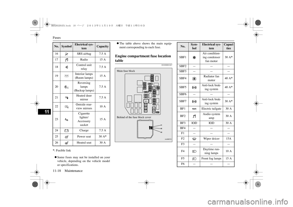
*: Fusible link�zSome fuses may not be installed on yourvehicle, depending on the vehicle modelor specifications.
�zThe table above shows the main equip-ment corresponding to each fuse.
E01008001867
16
SRS airbag 7.5 A
17
Radio 15 A
18
Control unit
relay
7.5 A
19
Interior lamps(Room lamps)
15 A
20
Reversing lamps
(Backup lamps)
7.5 A
21
Heated door
mirror
7.5 A
22
Outside rear-view mirrors
10 A
23
Cigarette lighter/Accessory socket
15 A
24
Charge 7.5 A
25
Power seat 30 A
*
26
Heated seat 30 A
No.
Symbol
Electrical sys-
tem
Capacity
Engine compartment fuse location table Behind of the fuse block coverMain fuse block
No.
Sym-bol
Electrical sys-
tem
Capacities
SBF1
Air condition-ing condenser fan motor
30 A
*
SBF2 — — —SBF3 — — —SBF4
Radiator fan
motor
40 A
*
SBF5
Anti-lock brak-ing system
40 A
*
SBF6 — — —SBF7
Anti-lock brak-ing system
30 A
*
BF1
Electric tailgate 30 A
BF2
Audio system
amp
30 A
BF3 IOD IOD 30 ABF4 — — —F1 — — —F2
Wiper deicer 15A
F3 — — —F4
Daytime run-ning lamps
10 A
F5
Front fog lamps 15 A
F6 — — —
BK0203201EN.book 18 ページ 2013年11月19日 火曜日 午前11時50分
Page 360 of 388
Fuses
Maintenance 11-19
11
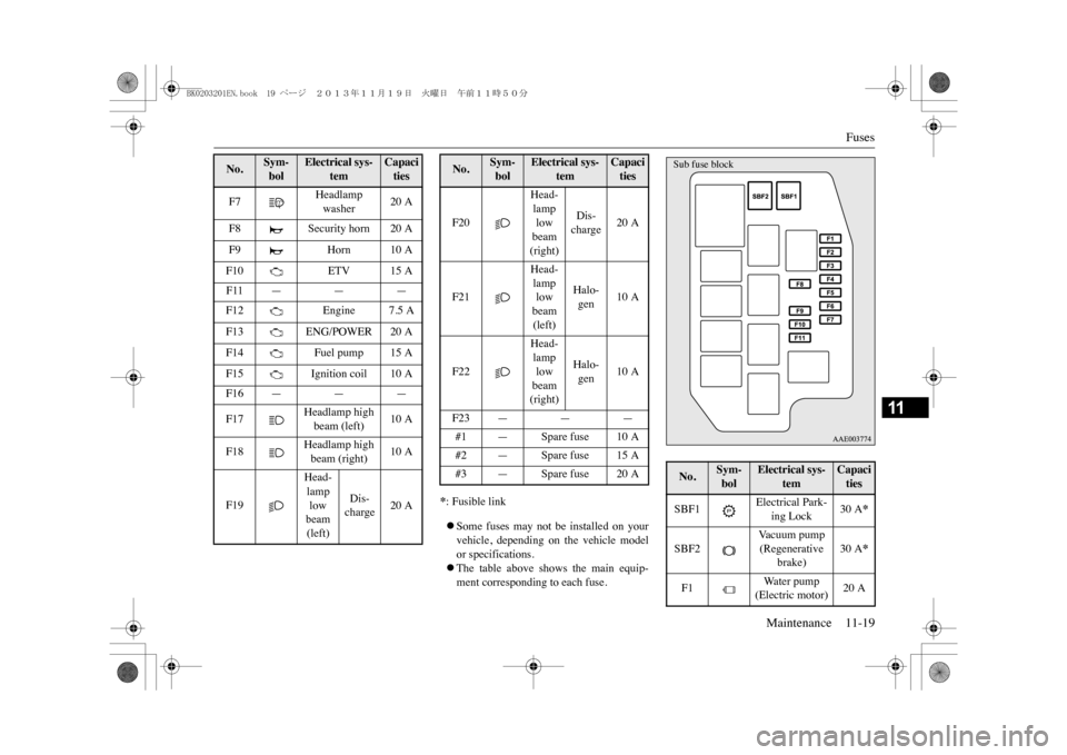
*: Fusible link�zSome fuses may not be installed on yourvehicle, depending on the vehicle modelor specifications.�zThe table above shows the main equip-ment corresponding to each fuse.
F7
Headlamp washer
20 A
F8
Security horn 20 A
F9
Horn 10 A
F10
ETV 15 A
F11 — — —F12
Engine 7.5 A
F13
ENG/POWER 20 A
F14
Fuel pump 15 A
F15
Ignition coil 10 A
F16 — — —F17
Headlamp high beam (left)
10 A
F18
Headlamp high beam (right)
10 A
F19
Head-lamp low beam (left)
Dis-charge
20 A
No.
Sym-bol
Electrical sys-
tem
Capacities
F20
Head-lamp low beam (right)
Dis-charge
20 A
F21
Head-lamp low beam (left)
Halo-gen
10 A
F22
Head-lamp low beam (right)
Halo-gen
10 A
F23 — — —#1 — Spare fuse 10 A#2 — Spare fuse 15 A#3 — Spare fuse 20 ANo.
Sym-bol
Electrical sys-
tem
Capacities
No.
Sym-bol
Electrical sys-
tem
Capacities
SBF1
Electrical Park-
ing Lock
30 A
*
SBF2
Va c u u m p u m p (Regenerative
brake)
30 A
*
F1
Water pump (Electric motor)
20 A
Sub fuse block
BK0203201EN.book 19 ページ 2013年11月19日 火曜日 午前11時50分