MITSUBISHI SPYDER 1990 Service Repair Manual
Manufacturer: MITSUBISHI, Model Year: 1990, Model line: SPYDER, Model: MITSUBISHI SPYDER 1990Pages: 2103, PDF Size: 68.98 MB
Page 161 of 2103
ENGINE OVERHAUL
11300850104
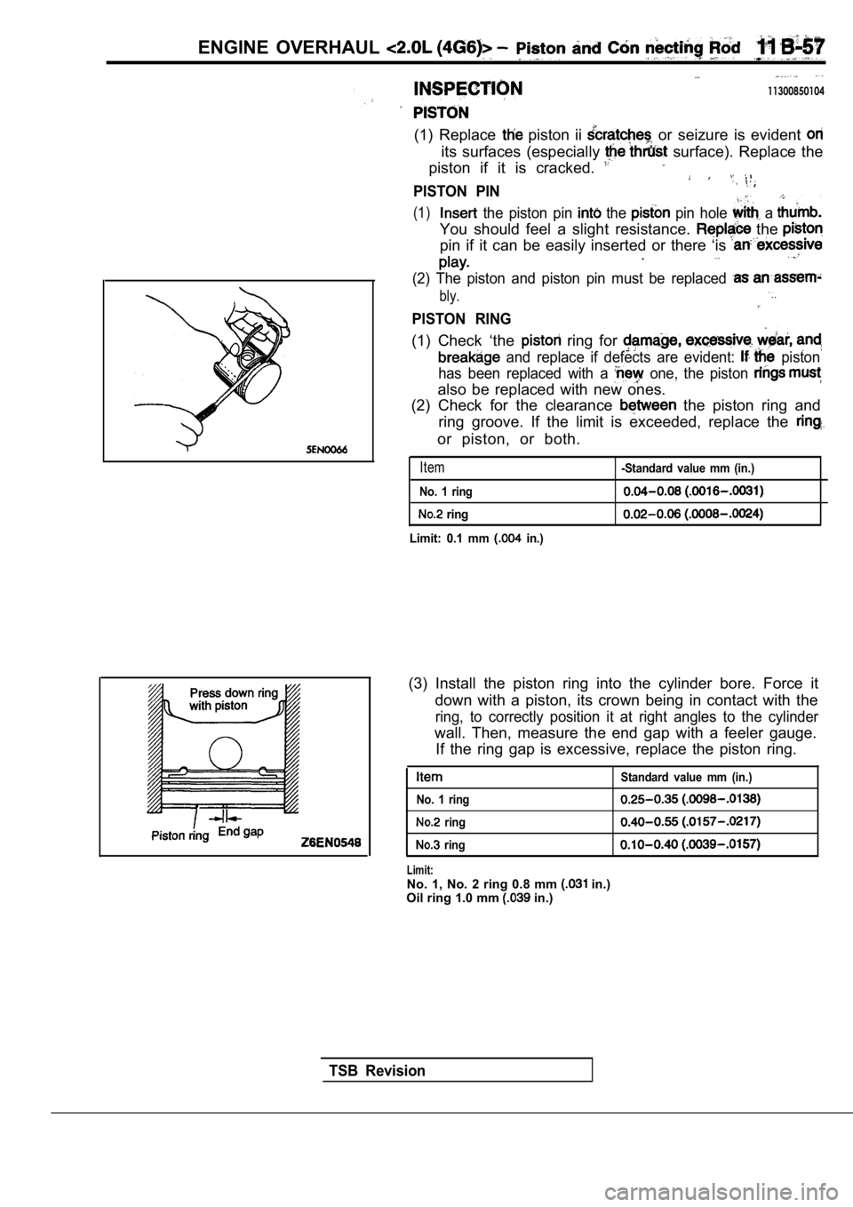
(1) Replace piston ii or seizure is evident
its surfaces (especially surface). Replace the
piston if it is cracked.
PISTON PIN
(1) the piston pin the pin hole a
You should feel a slight resistance. the
pin if it can be easily inserted or there ‘is .
(2) The piston and piston pin must be replaced
bly.
PISTON RING
(1) Check ‘the ring for
and replace if defects are evident: piston
has been replaced with a
one, the piston
also be replaced with new ones.
(2) Check for the clearance
the piston ring and
ring groove. If the limit is exceeded, replace the
or piston, or both.
Item
No. 1 ring
ring
Limit: 0.1 mm
in.)
-Standard value mm (in.)
(3) Install the piston ring into the cylinder bore. Force it
down with a piston, its crown being in contact with the
ring, to correctly position it at right angles to the cylinder
wall. Then, measure the end gap with a feeler gauge .
If the ring gap is excessive, replace the piston ri ng.
Standard value mm (in.)
No. 1 ring
ring
ring
Limit:No. 1, No. 2 ring 0.8 mm in.)
Oil ring 1.0 mm in.)
TSB Revision
Page 162 of 2103
ENGINE OVERHAUL Piston Rod
1I
PIN OIL CLEARANCE
(PLASTIGAGE METHOD)
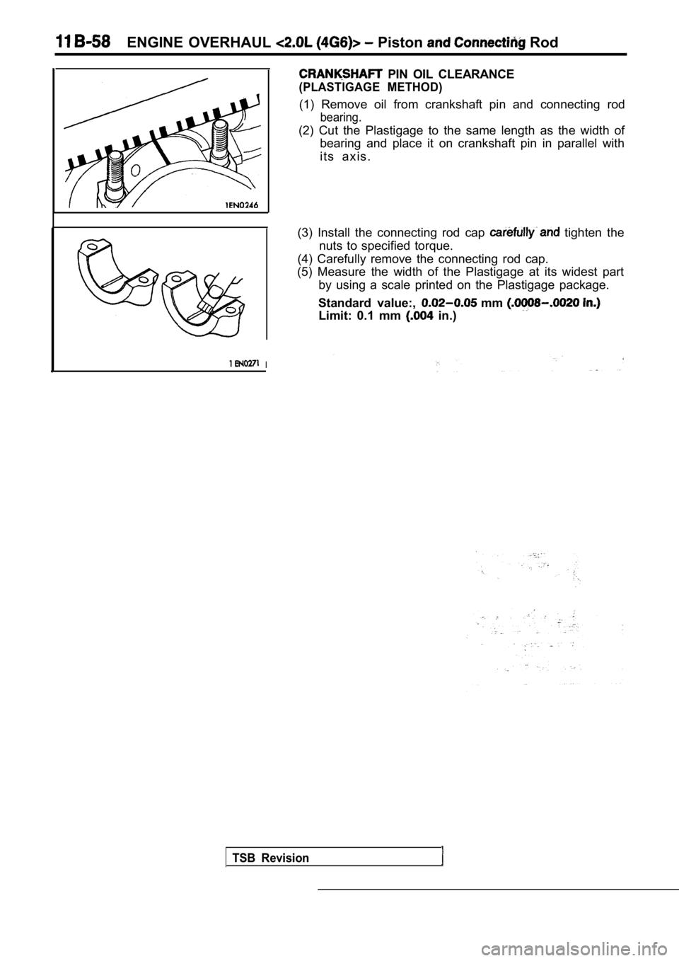
(1) Remove oil from crankshaft pin and connecting rod
bearing.
(2) Cut the Plastigage to the same length as the width of
bearing and place it on crankshaft pin in parallel with
i t s a x i s .
(3) Install the connecting rod cap
tighten the
nuts to specified torque.
(4) Carefully remove the connecting rod cap.
(5) Measure the width of the Plastigage at its wide st part
by using a scale printed on the Plastigage package.
Standard value:,
mm
Limit: 0.1 mm in.)
TSB Revision
Page 163 of 2103
E N G I N E O V E R H A U L
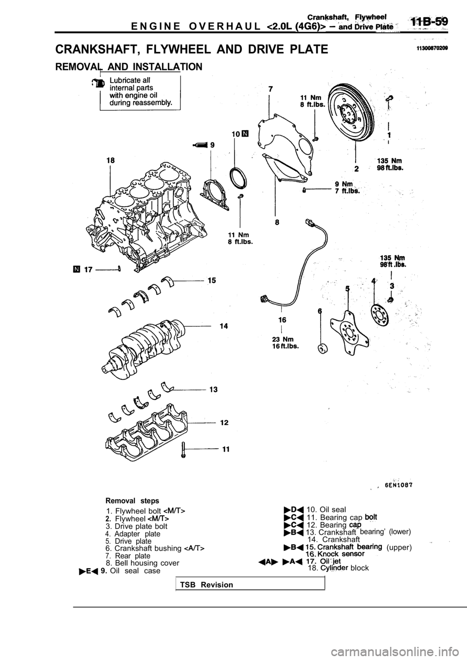
CRANKSHAFT, FLYWHEEL AND DRIVE PLATE
REMOVAL AND INSTALLATIONI
Removal steps
1. Flywheel bolt 2.Flywheel3. Drive plate bolt4.Adapter plate5.Drive plate6. Crankshaft bushing 7.Rear plate8. Bell housing cover 9. Oil seal case
,
10. Oil seal
11. Bearing cap 12. Bearing 13. Crankshaftbearing’ (lower)
14. Crankshaft
(upper)
18. block
TSB Revision
Page 164 of 2103
11
Crankshaft,
ENGINE OVERHAUL Drive Plate .
Timing belt side
Cylinder block bearing
bore identification mark
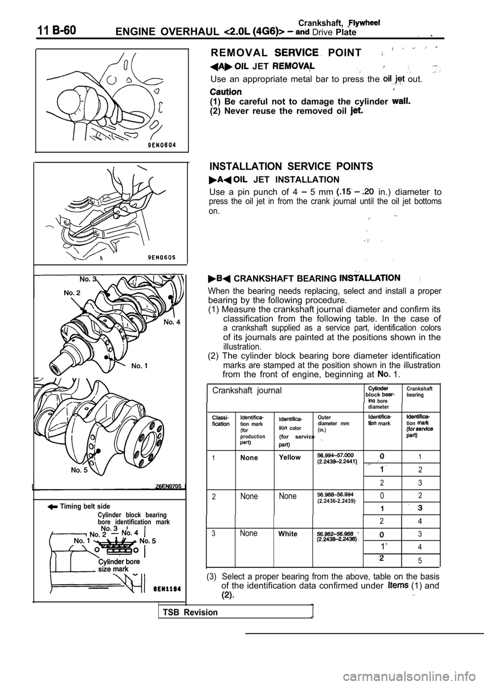
R E M O V A L POINT
JET
Use an appropriate metal bar to press the out.
(1) Be careful not to damage the cylinder
(2) Never reuse the removed oil
INSTALLATION SERVICE POINTS
JET INSTALLATION
Use a pin punch of 4
5 mm in.) diameter to
press the oil jet in from the crank journal until t he oil jet bottoms
on.
CRANKSHAFT BEARING
When the bearing needs replacing, select and instal l a proper
bearing by the following procedure.
(1) Measure the crankshaft journal diameter and confirm its
classification from the following table. In the cas e of
a crankshaft supplied as a service part, identification colors
of its journals are painted at the positions shown in the
illustration.
(2) The cylinder block bearing bore diameter identi fication
marks are stamped at the position shown in the illustration
from the front of engine, beginning at 1.
Crankshaft journalblock bore
diameter Crankshaft
bearing
tion mark(for
production
Outer
color diameter mm(in.)(for service
marktion
1None
Yellow1
2
23
2None
None02(2.2436-2.2439)
1
24
3NoneWhite3
1’4
5
(3)Select a proper bearing from the above, table on th
e basis
of the identification data confirmed under (1) and
TSB Revision
Page 165 of 2103
![MITSUBISHI SPYDER 1990 Service Repair Manual E N G I N E O V E R H A U L
ed
(for No. tion mark
Upper and lower (for No.3)
Identification
mark
1
Shank length
[Example]
(1) If the measured value of a crankshaft
diameter is b MITSUBISHI SPYDER 1990 Service Repair Manual E N G I N E O V E R H A U L
ed
(for No. tion mark
Upper and lower (for No.3)
Identification
mark
1
Shank length
[Example]
(1) If the measured value of a crankshaft
diameter is b](/img/19/57345/w960_57345-164.png)
E N G I N E O V E R H A U L
ed
(for No. tion mark
Upper and lower (for No.3)
Identification
mark
1
Shank length
[Example]
(1) If the measured value of a crankshaft
diameter is between 56.994 mm (2.2439
2.2441 in.), the journal is in the’
case the is also replaced by a
spare part, check the identification colors of the
journals painted on the
crankshaft. If the color’
is yellow, for example,.
journal is classified as
(2)
check the cylinder block bearing hole
mark stamped on the cylinder block.
If it is “O”, read the “Bearing identification column
to find the identification mark of the bearing to b e
used. In this case, it is “1”.
(4)
the bearings oil groove to the cylinder
block.
(5) Install the bearings having no oil to the bearing
caps.
CAP B E A R I N G C A P B O L T
INSTALLATION
(1) Install the bearing caps so that their arrows directed
to the timing belt side.
(2) Before installing the bearing cap bolts, check that the
shank length of each bolt meets the limit.
limit
is exceeded, replace the bolt.
(A): Max. 71.1 mm (2.79 in.)
(3) Apply engine oil to the threaded portion and be aring sur-
face of the bolt.
(4) Tighten the bolts to 25 Nm (16
in the specified
tightening sequence.
(5) Make a paint mark on the head of each bolt.
(6) Make a paint mark on the bearing cap at the pos ition
to from the paint mark made on the bolt in
the direction of tightening the bolt.
(7) According to the specified tightening sequence, give a
to turn to each bolt and make sure that the
paint mark on the bolt and that on the cap are in a lignment.
Caution
(1) If
thebolt is turned less than proper
performance may not be expected.
tightening the bolt, therefore, be careful to
a sufficient turn to it.
( 2 ) I f t h e b o l t i s
loosen the bolt completely and then retlghten
by repeating the tightening procedure from step
TSB Revision
Page 166 of 2103
11Crankshaft,ENGINE OVERHAUL and
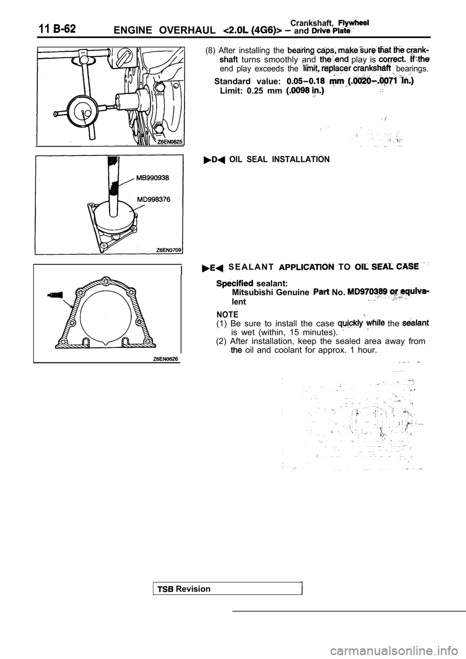
(8) After installing the
turns smoothly and play is
end play exceeds the bearings.
Standard value:
Limit: 0.25 mm
OIL SEAL INSTALLATION
Revision
S E A L A N T TO
sealant:
Mitsubishi Genuine
No.
lent
NOTE
(1) Be sure to install the case the
is wet (within, 15 minutes).
(2) After installation, keep the sealed area away f rom
oil and coolant for approx. 1 hour.
Page 167 of 2103
ENGINE OVERHAUL and
A
INSPECTION
O I L C L E A R A N C E
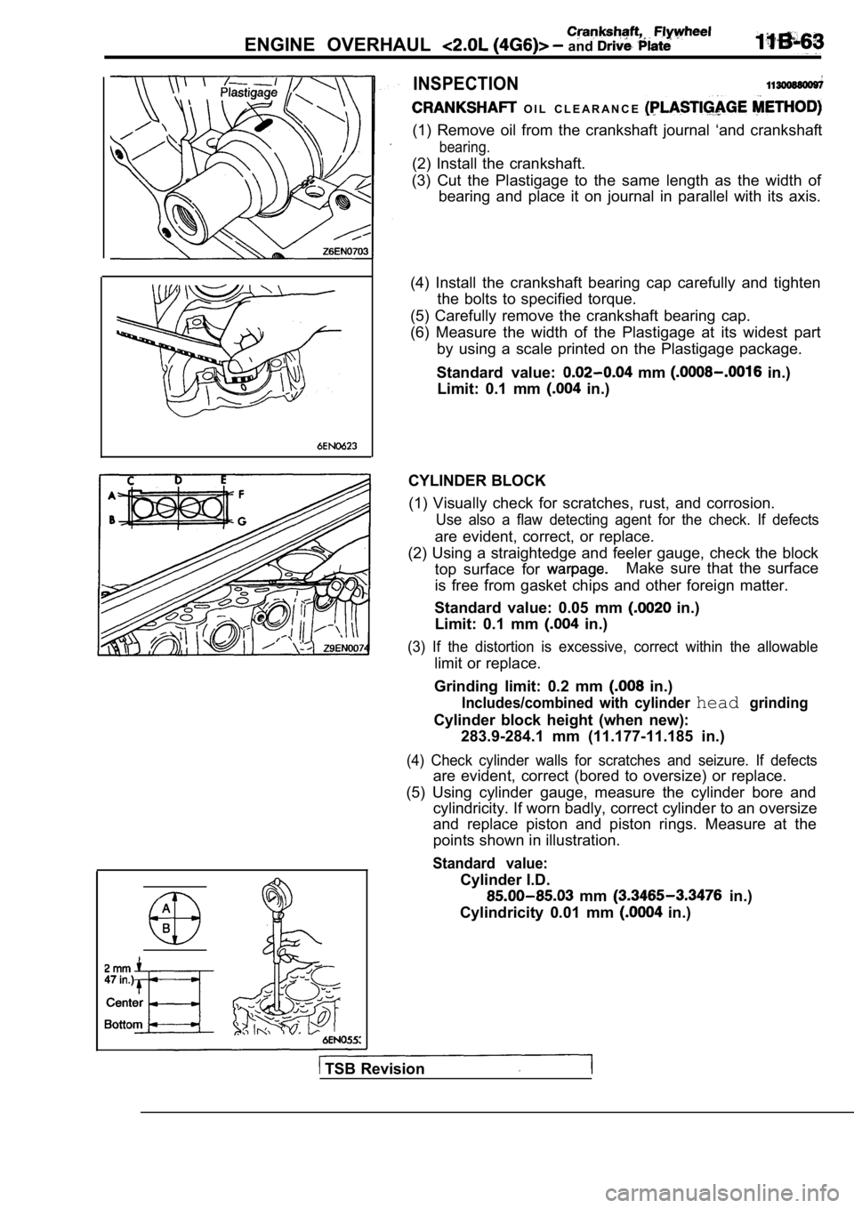
(1) Remove oil from the crankshaft journal ‘and crankshaft
bearing.
(2) Install the crankshaft.
(3) Cut the Plastigage to the same length as the wi dth of
bearing and place it on journal in parallel with it s axis.
(4) Install the crankshaft bearing cap carefully an d tighten
the bolts to specified torque.
(5) Carefully remove the crankshaft bearing cap.
(6) Measure the width of the Plastigage at its wide st part
by using a scale printed on the Plastigage package.
Standard value:
mm in.)
Limit: 0.1 mm
in.)
CYLINDER BLOCK (1) Visually check for scratches, rust, and corrosi on.
Use also a flaw detecting agent for the check. If d efects
are evident, correct, or replace.
(2) Using a straightedge and feeler gauge, check th e block
top surface for
Make sure that the surface
is free from gasket chips and other foreign matter.
Standard value: 0.05 mm
in.)
Limit: 0.1 mm
in.)
(3) If the distortion is excessive, correct within the allowable
limit or replace.
Grinding limit: 0.2 mm
in.)
Includes/combined with cylinder headgrinding
Cylinder block height (when new): 283.9-284.1 mm (11.177-11.185 in.)
(4) Check cylinder walls for scratches and seizure. If defects
are evident, correct (bored to oversize) or replace.
(5) Using cylinder gauge, measure the cylinder bore and
cylindricity. If worn badly, correct cylinder to an oversize
and replace piston and piston rings. Measure at the
points shown in illustration.
Standard value:
Cylinder I.D.
mm in.)
Cylindricity 0.01 mm
in.)
TSB Revision
Page 168 of 2103
ENGINE OVERHAUL and Drive Plate
, Flywheel
Thrustdirection
BORING CYLINDER
(1) Oversize pistons to be used should be determine d
the basis of the largest bore cylinder.
Piston size identification
Size
0.50
1
NOTE
Identification mark
1.00
Size mark is stamped on piston top,
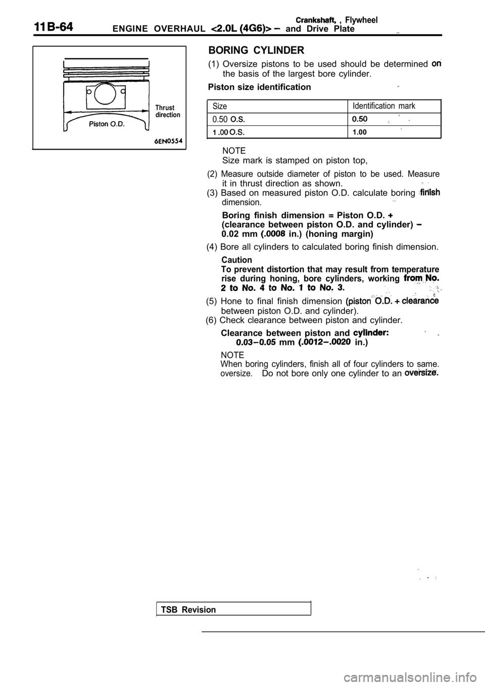
(2) Measure outside diameter of piston to be used. Measure
it in thrust direction as shown.
(3) Based on measured piston O.D. calculate boring
dimension.
Boring finish dimension Piston O.D.
(clearance between piston O.D. and cylinder)
0.02 mm in.) (honing margin)
(4) Bore all cylinders to calculated boring finish dimension.
Caution
To prevent distortion that may result from temperat ure
rise during honing, bore cylinders, working
(5) Hone to final finish dimension
between piston O.D. and cylinder).
(6) Check clearance between piston and cylinder.
Clearance between piston and
mm in.)
NOTE
When boring cylinders, finish all of four cylinders to same.
oversize.Do not bore only one cylinder to an
TSB Revision
Page 169 of 2103
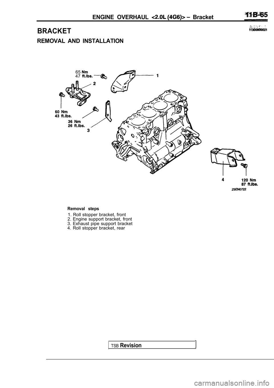
6547
Removal steps
1. Roll stopper bracket, front
2. Engine support bracket, front
3. Exhaust pipe support bracket
4. Roll stopper bracket, rear
BRACKET
ENGINE OVERHAUL Bracket
REMOVAL AND INSTALLATION
TSBRevision
Page 170 of 2103
11
NOTES .
,