MITSUBISHI SPYDER 1990 Service Repair Manual
SPYDER 1990
MITSUBISHI
MITSUBISHI
https://www.carmanualsonline.info/img/19/57345/w960_57345-0.png
MITSUBISHI SPYDER 1990 Service Repair Manual
Trending: adding oil, light, driver seat adjustment, width, heater, center console, check oil
Page 321 of 2103
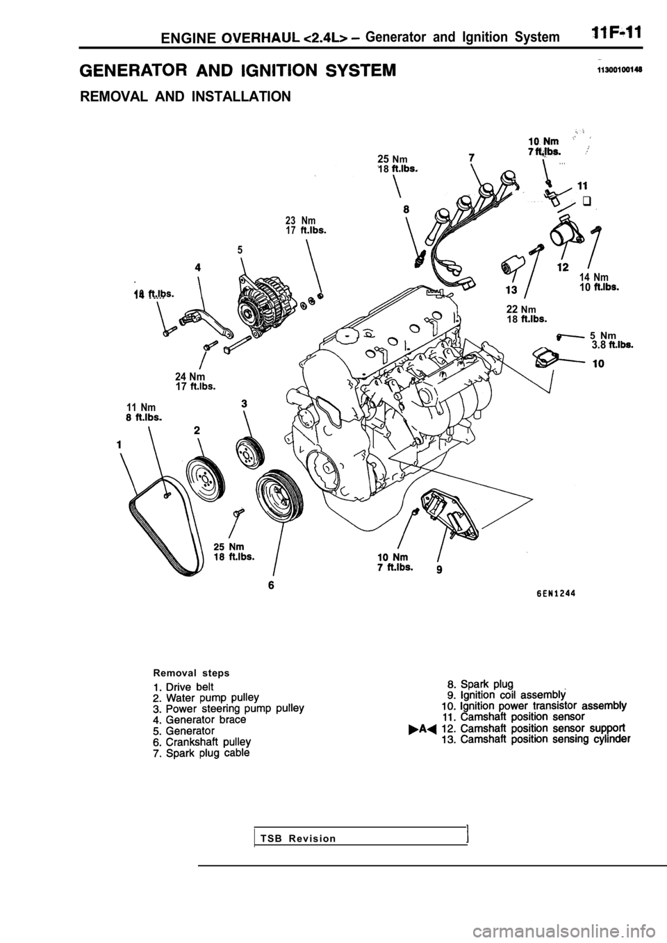
ENGINEGenerator and Ignition System
REMOVAL AND INSTALLATION
23 Nm17
5
10
25Nm18. . .
q
14 Nm10
22Nm18
5 Nm3.8
Removal steps
24 Nm17
11 Nm
T S B R e v i s i o n
Page 322 of 2103
11ENGINE OVERHAUL Generator and
TSBRevision
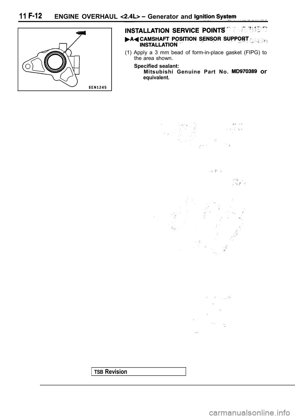
(1) Apply a 3 mm bead of form-in-place gasket (FIPG) to
the area shown.
Specified sealant: M i t s u b i s h i G e n u i n e P a r t N o .
or
equivalent.
Page 323 of 2103
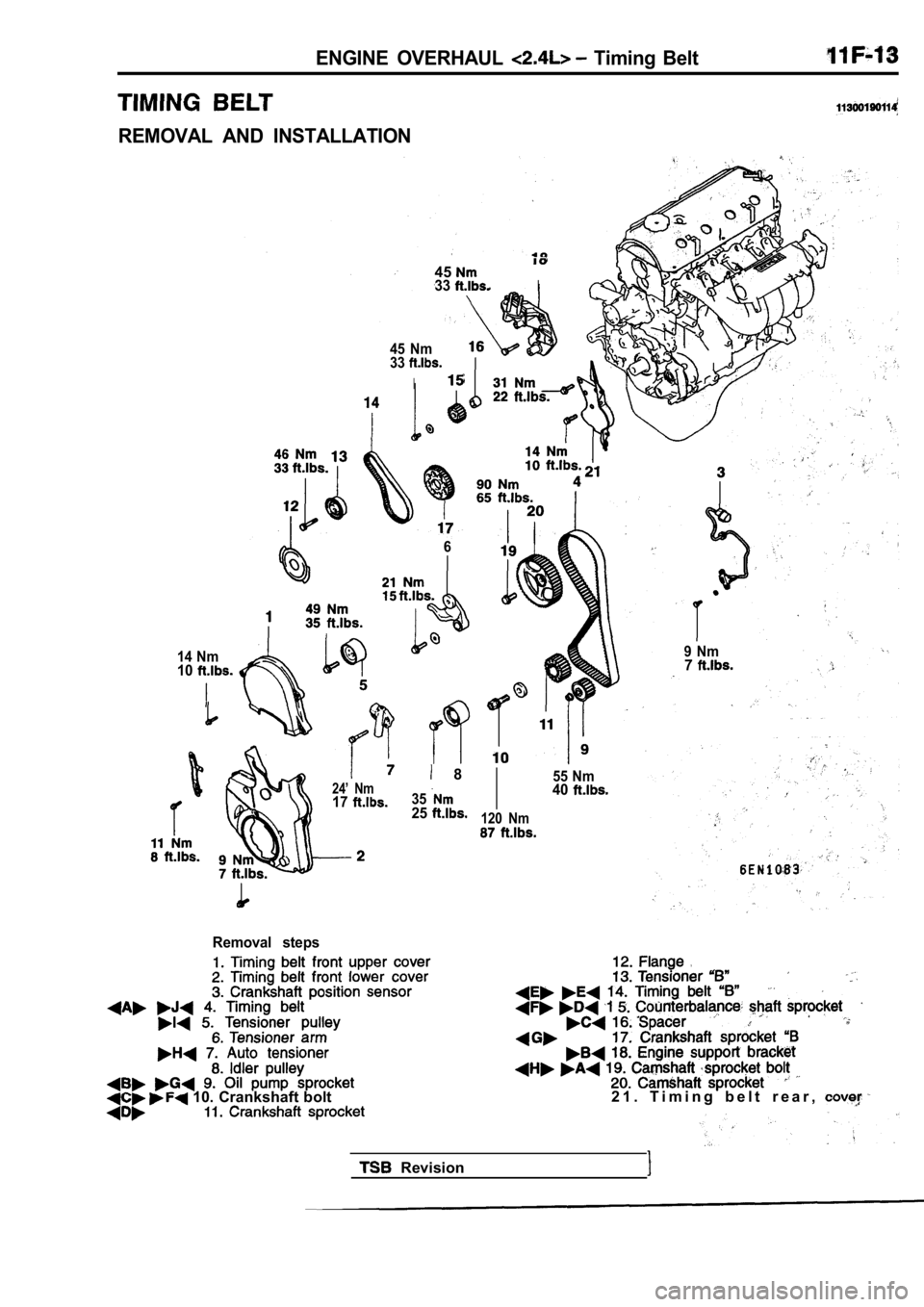
ENGINE OVERHAUL Timing Belt
REMOVAL AND INSTALLATION
4533I
45 Nm
33
I
24’ Nm17
55 Nm40
120 Nm
6
14 Nm
10
8
3525
9 Nm7
Removal steps
10. Crankshaft bolt2 1 . T i m i n g b e l t r e a r ,
Revision
Page 324 of 2103
ENGINE OVERHAUL Timing Belt , ,
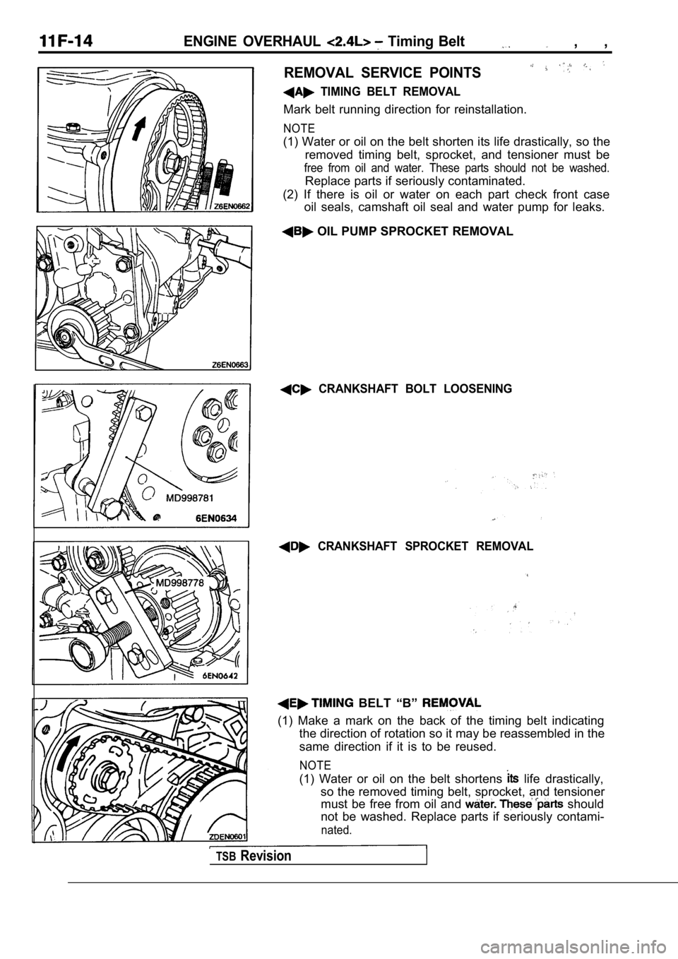
REMOVAL SERVICE POINTS
TIMING BELT REMOVAL
Mark belt running direction for reinstallation.
NOTE
(1) Water or oil on the belt shorten its life drastically, so the
removed timing belt, sprocket, and tensioner must b e
free from oil and water. These parts should not be washed.
Replace parts if seriously contaminated.
(2) If there is oil or water on each part check fro nt case
oil seals, camshaft oil seal and water pump for lea ks.
OIL PUMP SPROCKET REMOVAL
CRANKSHAFT BOLT LOOSENING
CRANKSHAFT SPROCKET REMOVAL
BELT “B”
(1) Make a mark on the back of the timing belt indi cating
the direction of rotation so it may be reassembled in the
same direction if it is to be reused.
NOTE
(1) Water or oil on the belt shortens life drastically,
so the removed timing belt, sprocket, and tensioner must be free from oil and
should
not be washed. Replace parts if seriously contami-
nated.
TSBRevision
Page 325 of 2103
ENGINE OVERHAUL Timing Belt
(2) If there is oil or water on each part check front case
oil seals, camshaft oil seal and water pump leaks.’
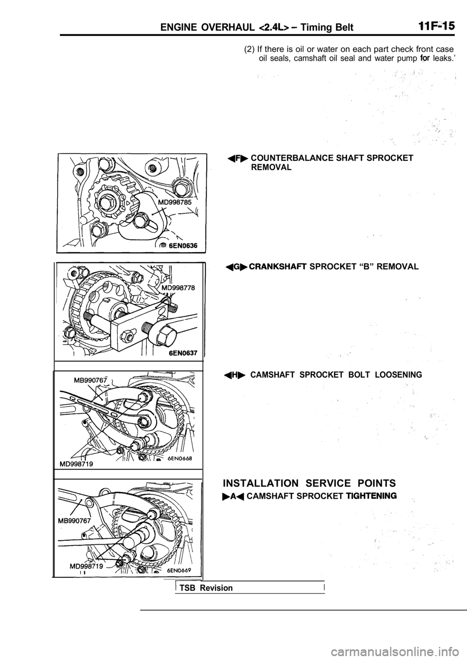
COUNTERBALANCE SHAFT SPROCKET
REMOVAL
SPROCKET “B” REMOVAL
CAMSHAFT SPROCKET BOLT LOOSENING
INSTALLATION SERVICE POINTS
CAMSHAFT SPROCKET
TSB RevisionI
Page 326 of 2103
ENGINE OVERHAUL Timing,
ENGINE SUPPORT BRACKET INSTALLATION
Spacer
Coat the bolts illustrated with sealant before tightening.
Specified sealant:
ATD Part No. 8660 or equivalent
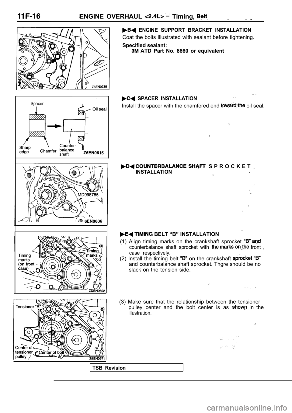
SPACER INSTALLATION
Install the spacer with the chamfered end oil seal.
,
S P R O C K E T
INSTALLATION.
,
BELT “B” INSTALLATION
(1) Align timing marks on the crankshaft sprocket
counterbalance shaft sprocket with front ,
case respectively.
(2) Install the timing belt on the crankshaft
and counterbalance shaft sprocket. Thgre should be no
slack on the tension side.
(3) Make sure that the relationship between the ten sioner
pulley center and the bolt center is as
in the
illustration.
TSB Revision
Page 327 of 2103
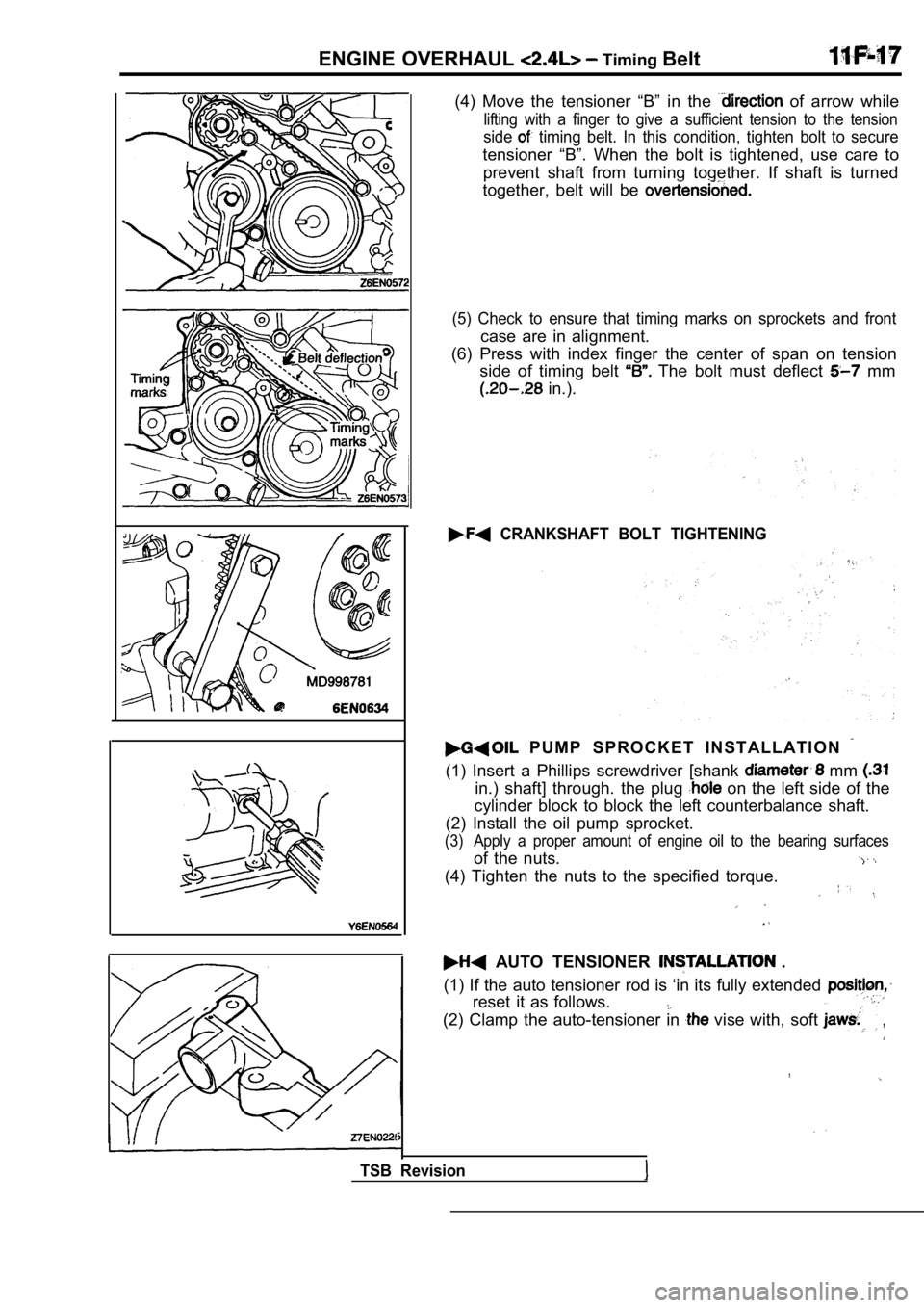
ENGINE OVERHAUL Timing Belt
(4) Move the tensioner “B” in the of arrow while
lifting with a finger to give a sufficient tension to the tension
side timing belt. In this condition, tighten bolt to secure
tensioner “B”. When the bolt is tightened, use care to
prevent shaft from turning together. If shaft is tu rned
together, belt will be
(5) Check to ensure that timing marks on sprockets and front
case are in alignment.
(6) Press with index finger the center of span on t ension
side of timing belt
The bolt must deflect mm
in.).
CRANKSHAFT BOLT TIGHTENING
P U M P S P R O C K E T I N S T A L L A T I O N
(1) Insert a Phillips screwdriver [shank mm
in.) shaft] through. the plug on the left side of the
cylinder block to block the left counterbalance sha ft.
(2) Install the oil pump sprocket.
(3) Apply a proper amount of engine oil to the beari ng surfaces
of the nuts.
(4) Tighten the nuts to the specified torque.
AUTO TENSIONER .
(1) If the auto tensioner rod is ‘in its fully exte nded
reset it as follows.
(2) Clamp the auto-tensioner in vise with, soft ,
TSB Revision
Page 328 of 2103
E N G I N E O V E R H A U L Belt
(3) Push in the rod little by little with the until the set
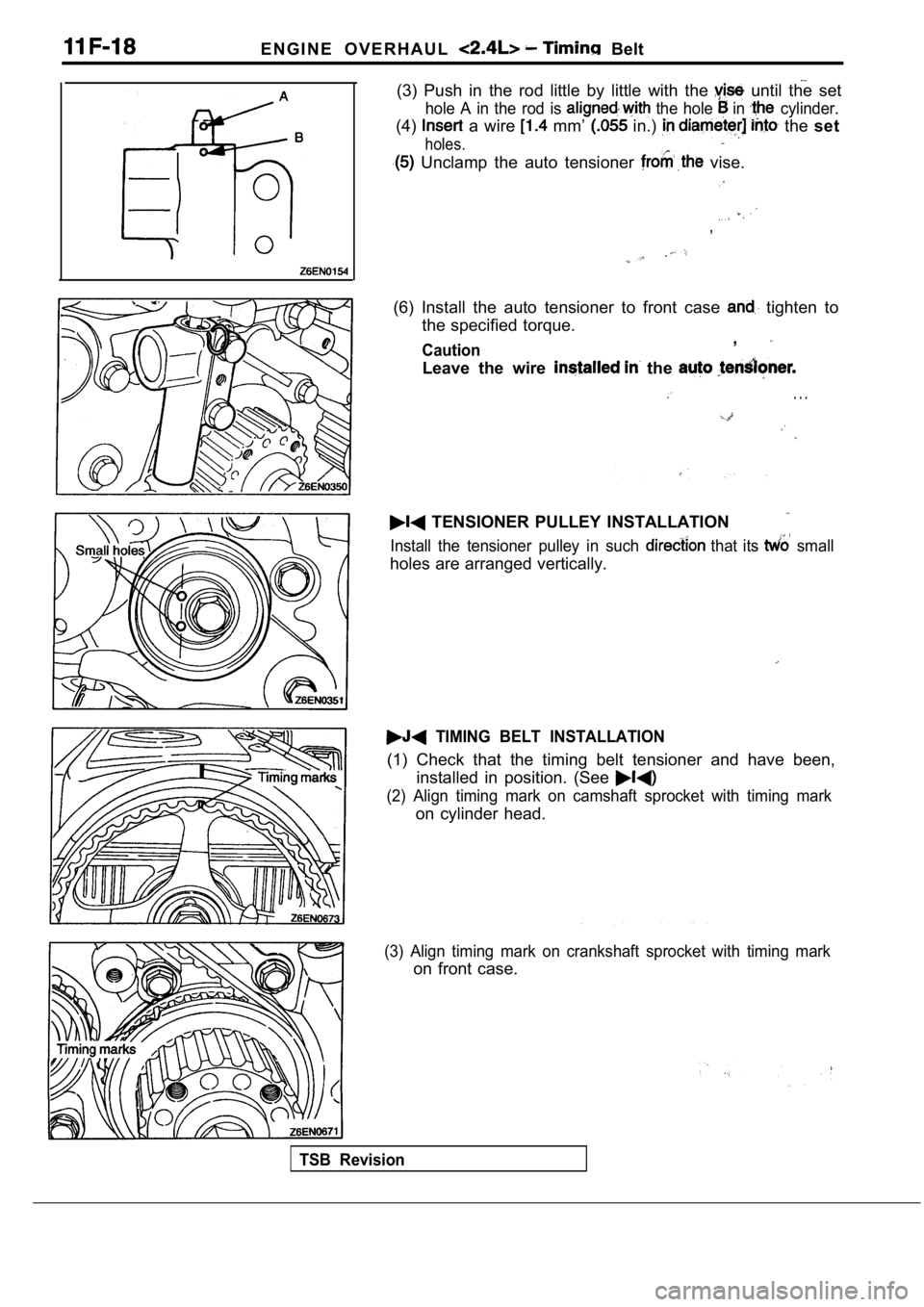
hole A in the rod is the hole in cylinder.
(4) a wire mm’ in.) the set
holes.
Unclamp the auto tensioner vise.
,
(6) Install the auto tensioner to front case tighten to
the specified torque.
Caution,
Leave the wire the
. . .
TENSIONER PULLEY INSTALLATION
Install the tensioner pulley in such that its small
holes are arranged vertically.
TIMING BELT INSTALLATION
(1) Check that the timing belt tensioner and have b een,
installed in position. (See
(2) Align timing mark on camshaft sprocket with tim ing mark
on cylinder head.
(3) Align timing mark on crankshaft sprocket with timing mark
on front case.
TSB Revision
Page 329 of 2103
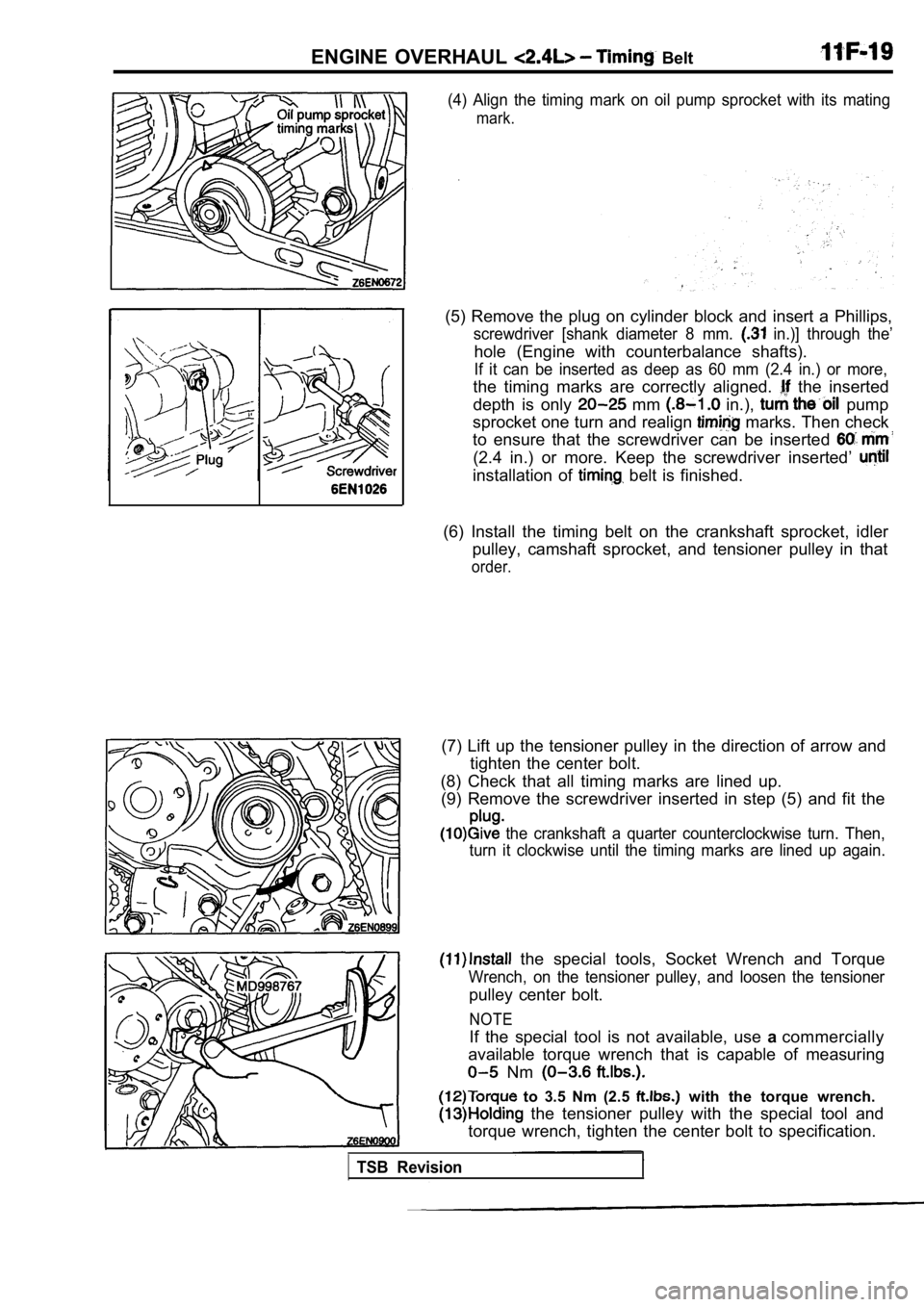
ENGINE OVERHAUL Belt
(4) Align the timing mark on oil pump sprocket with its mating
mark.
(5) Remove the plug on cylinder block and insert a Phillips,
screwdriver [shank diameter 8 mm. in.)] through the’
hole (Engine with counterbalance shafts).
If it can be inserted as deep as 60 mm (2.4 in.) or more,
the timing marks are correctly aligned. the inserted
depth is only
mm in.), pump
sprocket one turn and realign
marks. Then check
to ensure that the screwdriver can be inserted
(2.4 in.) or more. Keep the screwdriver inserted’
installation of belt is finished.
(6) Install the timing belt on the crankshaft sproc ket, idler
pulley, camshaft sprocket, and tensioner pulley in that
order.
(7) Lift up the tensioner pulley in the direction of arrow and
tighten the center bolt.
(8) Check that all timing marks are lined up. (9) Remove the screwdriver inserted in step (5) and fit the
the crankshaft a quarter counterclockwise turn. Then,
turn it clockwise until the timing marks are lined up again.
the special tools, Socket Wrench and Torque
Wrench, on the tensioner pulley, and loosen the ten sioner
pulley center bolt.
to 3.5 Nm (2.5 with the torque wrench.
the tensioner pulley with the special tool and
torque wrench, tighten the center bolt to specifica tion.
NOTE
If the special tool is not available, use acommercially
available torque wrench that is capable of measurin g
Nm
TSB Revision
Page 330 of 2103
ENGINE OVERHAUL .
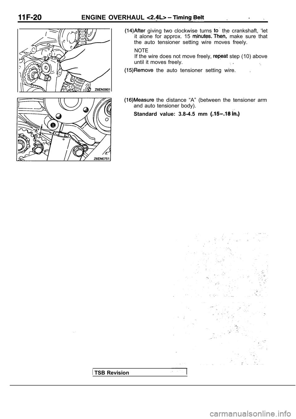
giving two clockwise turns the crankshaft, ‘let
it alone for approx. 15
make sure that
the auto tensioner setting wire moves freely.
NOTE
If the wire does not move freely, step (10) above
until it moves freely.
the auto tensioner setting wire.,
TSB Revision
the distance “A” (between the tensioner arm
and auto tensioner body).
Standard value: 3.8-4.5 mm
Trending: tire pressure, air bleeding, overheating, battery replacement, radio antenna, four wheel drive, mirror
