MITSUBISHI SPYDER 1990 Service Repair Manual
SPYDER 1990
MITSUBISHI
MITSUBISHI
https://www.carmanualsonline.info/img/19/57345/w960_57345-0.png
MITSUBISHI SPYDER 1990 Service Repair Manual
Trending: ECU, wheelbase, oil viscosity, coolant temperature, steering wheel adjustment, clock setting, charging
Page 331 of 2103
ENGINE OVERHAUL Timing
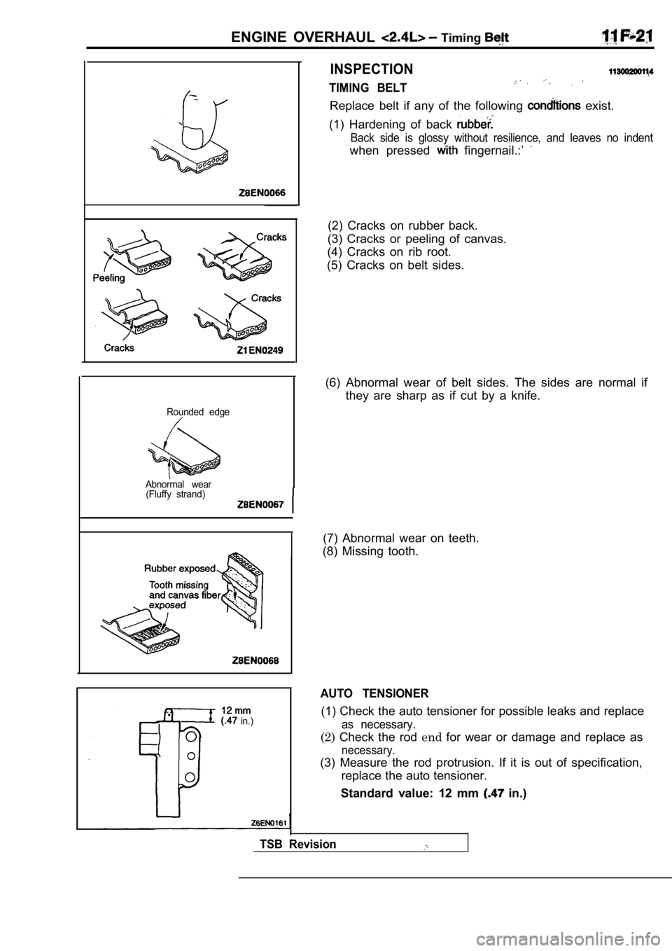
Rounded edge
Abnormal wear (Fluffy strand)
in.)(1) Check the auto tensioner for possible leaks and replace
as necessary.
INSPECTION
TIMING BELT
Replace belt if any of the following exist.
(1) Hardening of back
Back side is glossy without resilience, and leaves no indent
when pressed fingernail.:’
(2) Cracks on rubber back.
(3) Cracks or peeling of canvas.
(4) Cracks on rib root.
(5) Cracks on belt sides.
(6) Abnormal wear of belt sides. The sides are norm al if
they are sharp as if cut by a knife.
(7) Abnormal wear on teeth.
(8) Missing tooth.
AUTO TENSIONER
(2) Check the rod endfor wear or damage and replace as
necessary.
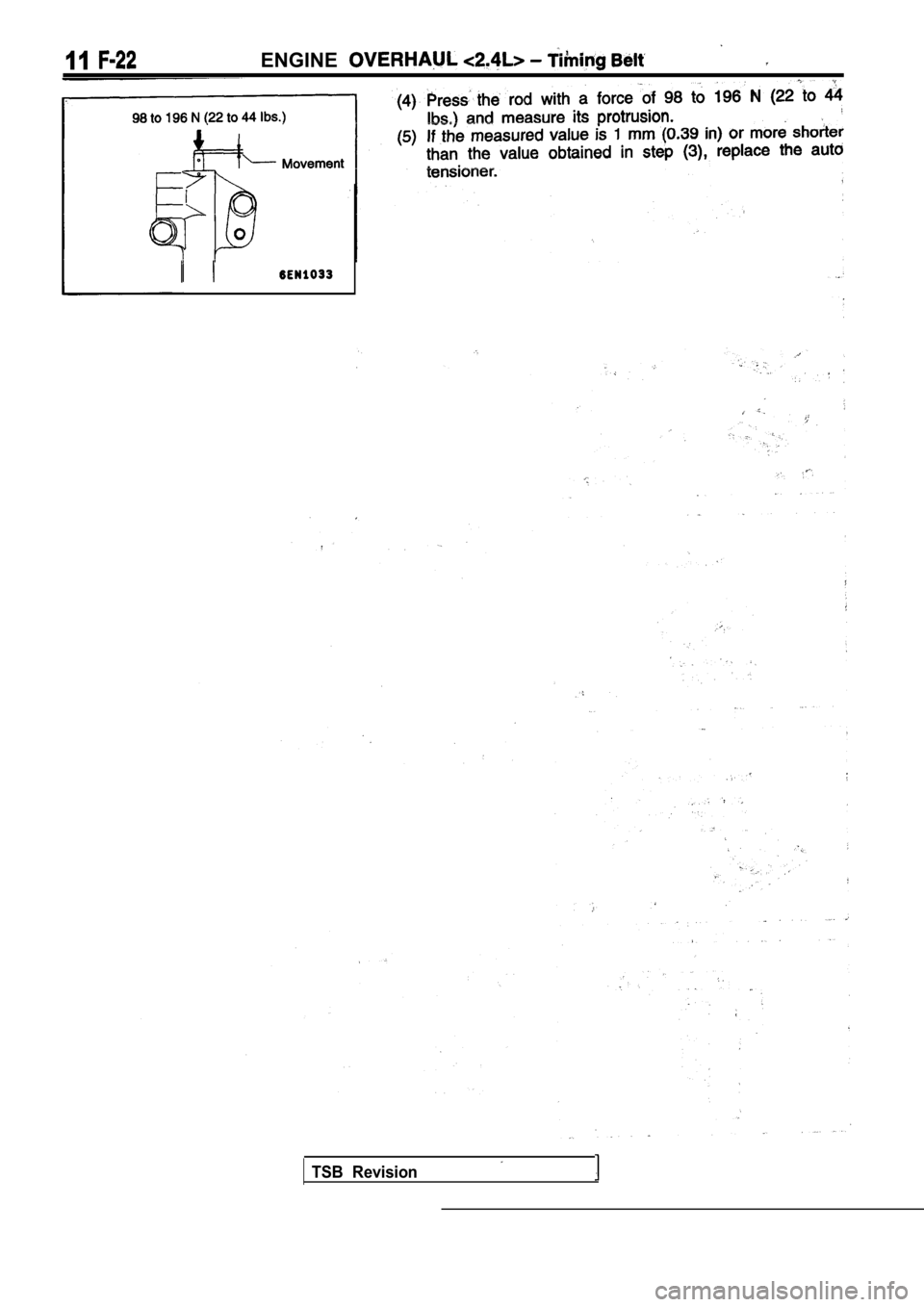
(3) Measure the rod protrusion. If it is out of spe cification,
replace the auto tensioner.
Standard value: 12 mm
in.)
TSB Revision
Page 332 of 2103
Page 333 of 2103
Fuel and Emission Parts
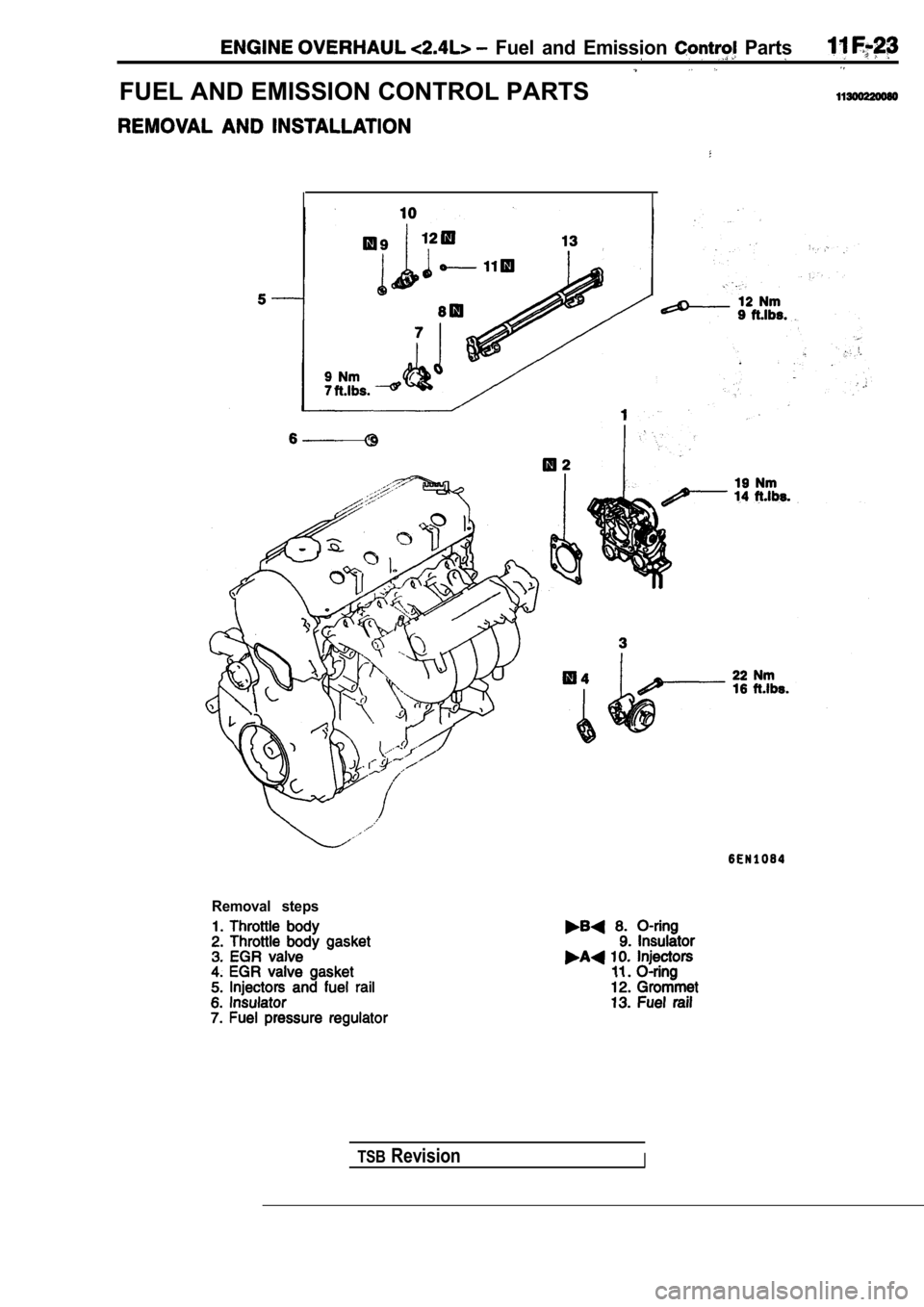
FUEL AND EMISSION CONTROL PARTS
Removal steps
TSBRevisionI
Page 334 of 2103
, . .
11 ENGINE OVERHAUL Fuel and . .
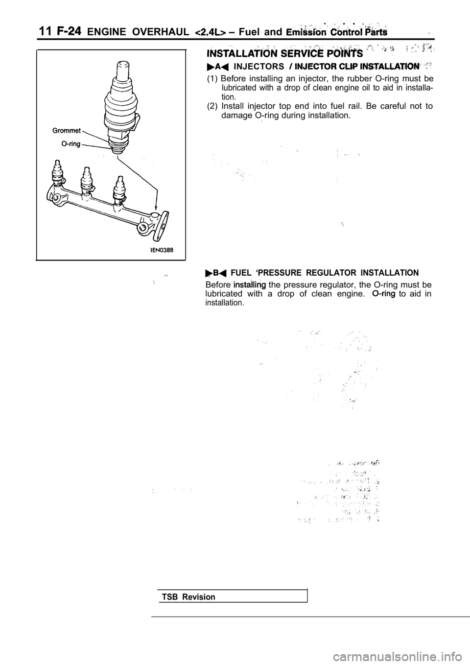
INJECTORS
(1) Before installing an injector, the rubber O-ring must be
lubricated with a drop of clean engine oil to aid in installa-
tion.
(2) Install injector top end into fuel rail. Be careful not to
damage O-ring during installation.
FUEL ‘PRESSURE REGULATOR INSTALLATION
Before the pressure regulator, the O-ring must be
lubricated with a drop of clean engine.
to aid in
installation.
TSB Revision
Page 335 of 2103
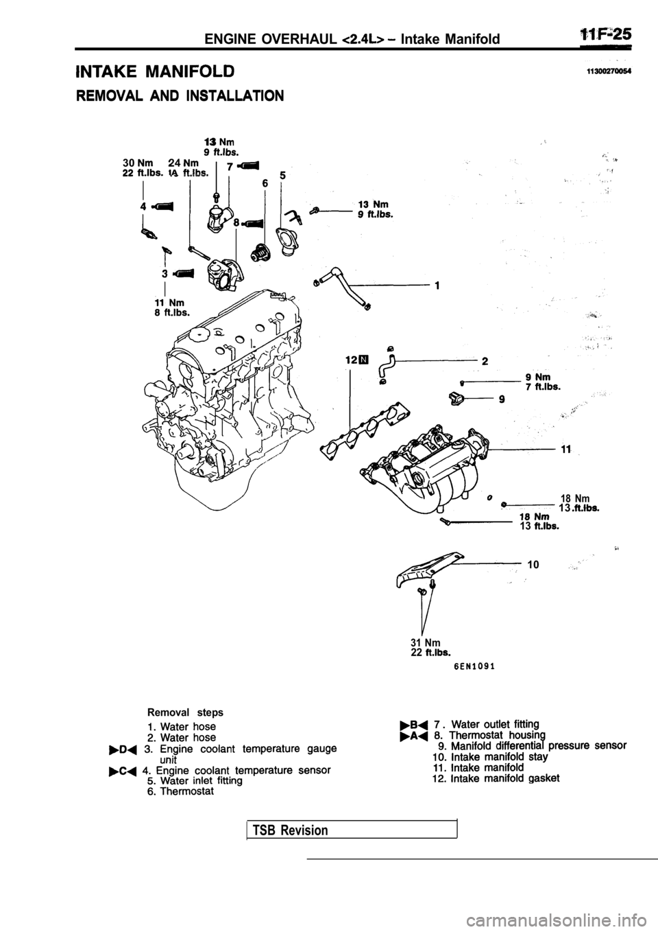
ENGINE OVERHAUL Intake Manifold
REMOVAL AND INSTALLATION
REMOVAL AND INSTALLATION
3024IAI
13
18 Nm 13
13
10
31 Nm22
Removal steps
7 .
TSB Revision
Page 336 of 2103
ENGINE OVERHAUL intake Manifold
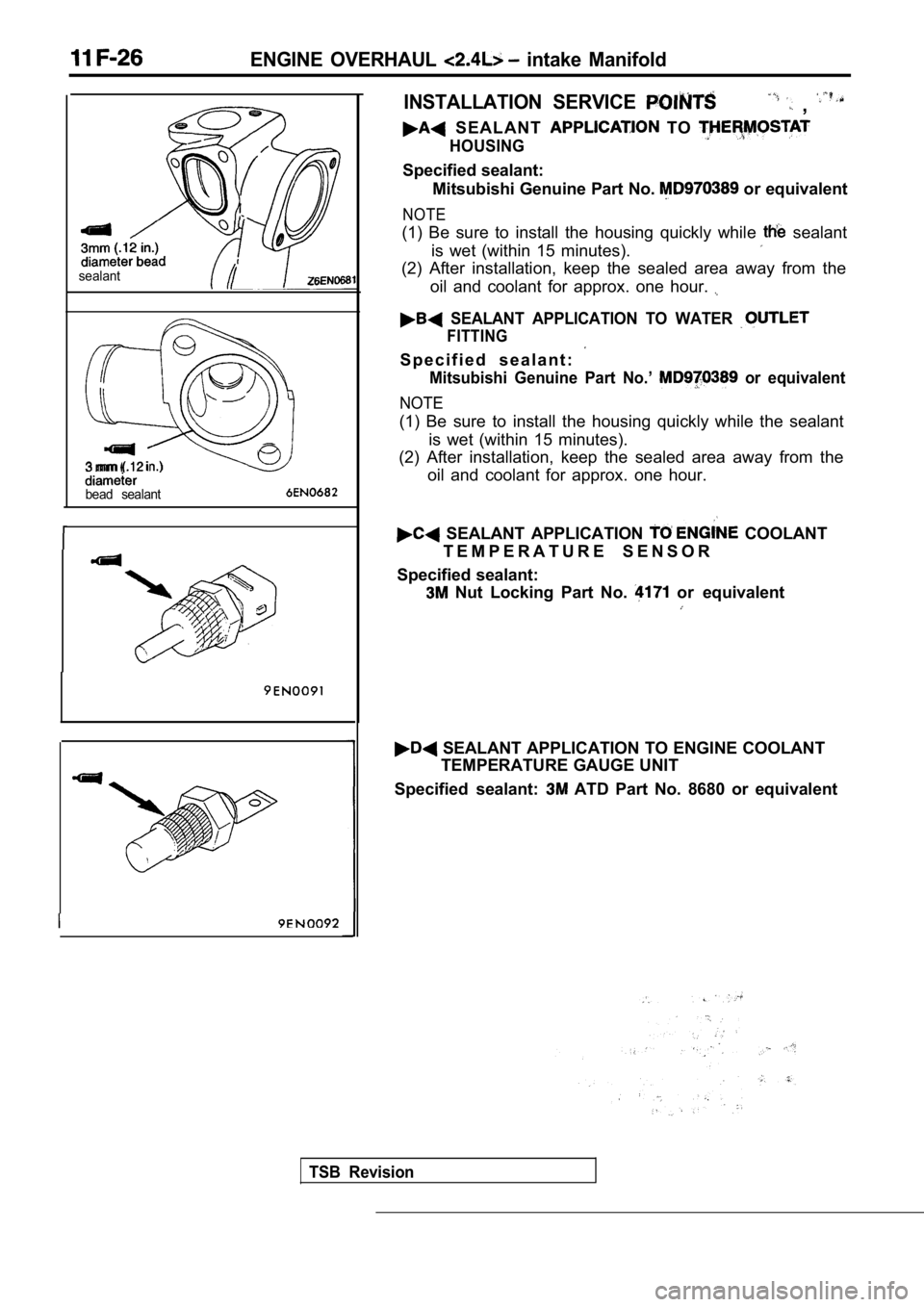
sealant
3 mm
bead sealant
INSTALLATION SERVICE ,
S E A L A N T TO
HOUSING
Specified sealant:Mitsubishi Genuine Part No.
or equivalent
NOTE
(1) Be sure to install the housing quickly while sealant
is wet (within 15 minutes).
(2) After installation, keep the sealed area away f rom the
oil and coolant for approx. one hour.
SEALANT APPLICATION TO WATER
FITTING
S p e c i f i e d s e a l a n t :
Mitsubishi Genuine Part No.’ or equivalent
NOTE
(1) Be sure to install the housing quickly while th e sealant
is wet (within 15 minutes).
(2) After installation, keep the sealed area away f rom the
oil and coolant for approx. one hour.
SEALANT APPLICATION COOLANT
T E M P E R A T U R E S E N S O R
Specified sealant:
Nut Locking Part No. or equivalent
SEALANT APPLICATION TO ENGINE COOLANT TEMPERATURE GAUGE UNIT
Specified sealant:
ATD Part No. 8680 or equivalent
TSB Revision
Page 337 of 2103
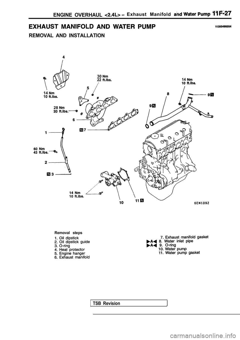
ENGINE OVERHAUL Exhaust Manifold
REMOVAL AND INSTALLATION
3022
1410
28
14
Removal steps
TSB Revision
Page 338 of 2103
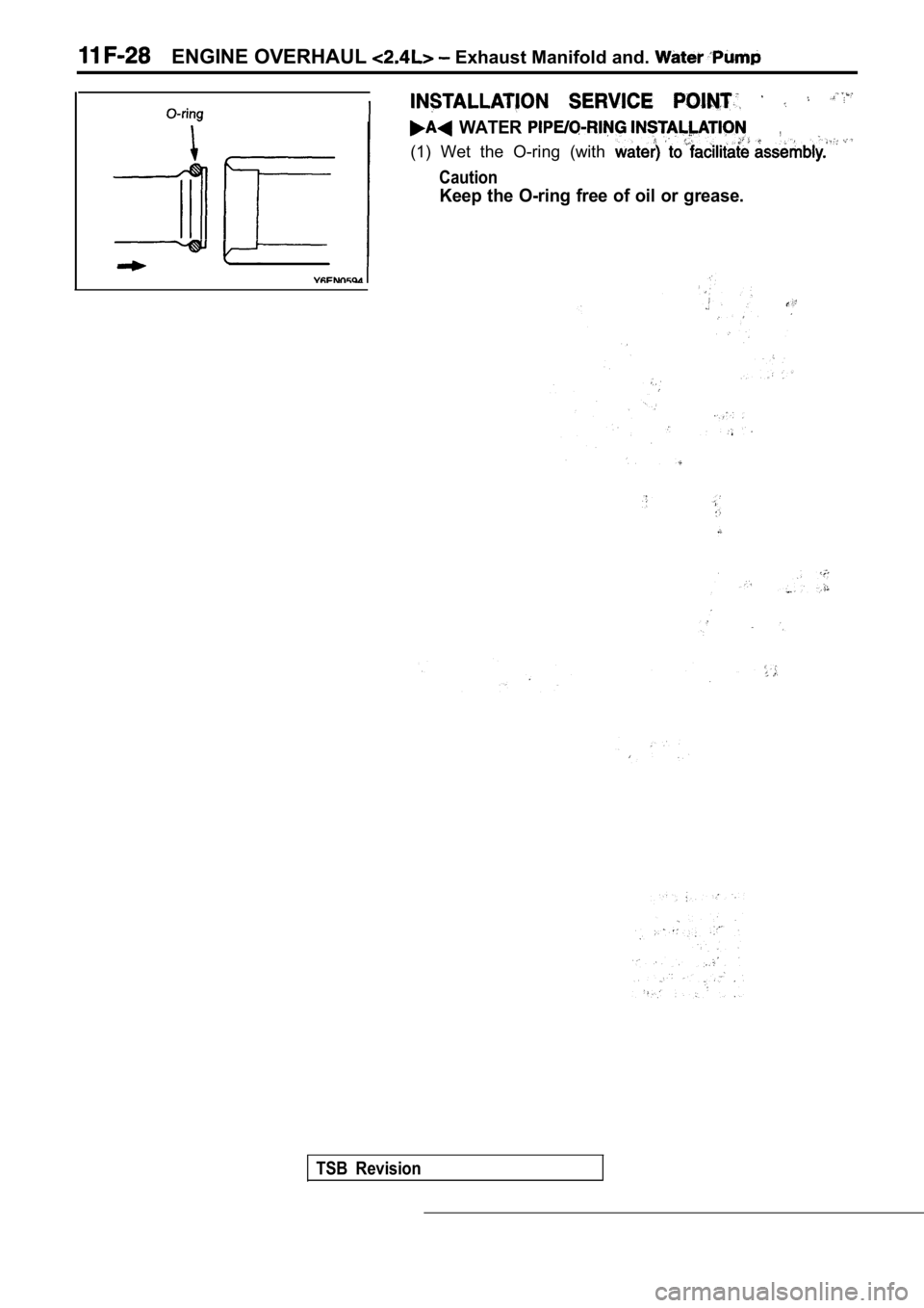
ENGINE OVERHAUL Exhaust Manifold and.
WATER ,
(1) Wet the O-ring (with
Caution
Keep the O-ring free of oil or grease.
TSB Revision
Page 339 of 2103
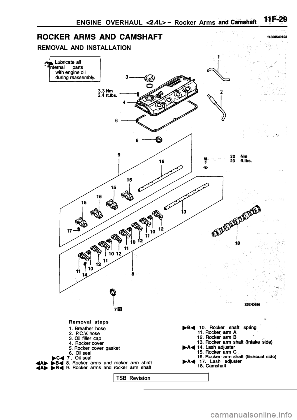
ENGINE OVERHAUL Rocker Arms
REMOVAL AND INSTALLATION
3.32.4
6
2
R e m o v a l s t e p s
2.
4.
6. 7 .
TSB Revision
Page 340 of 2103
ENGINE OVERHAUL Rocker Arms and Camshaft
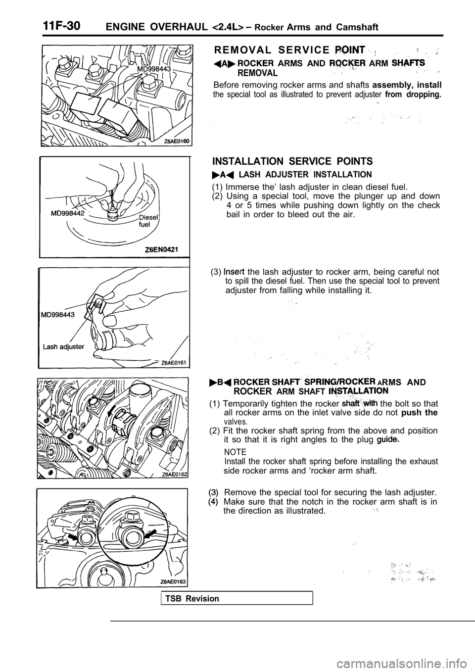
R E M O V A L S E R V I C E
ARMS AND ARM
REMOVAL.
Before removing rocker arms and shafts assembly, install
the special tool as illustrated to prevent adjuster from dropping.
INSTALLATION SERVICE POINTS
LASH ADJUSTER INSTALLATION
(1) Immerse the’ lash adjuster in clean diesel fuel .
(2) Using a special tool, move the plunger up and d own
4 or 5 times while pushing down lightly on the chec k
bail in order to bleed out the air.
(3)
the lash adjuster to rocker arm, being careful not
to spill the diesel fuel. Then use the special tool to prevent
adjuster from falling while installing it.
ARMS AND
ROCKERARM SHAFT
(1) Temporarily tighten the rocker the bolt so that
all rocker arms on the inlet valve side do not push the
valves.
(2) Fit the rocker shaft spring from the above and position
it so that it is right angles to the plug
NOTE
Install the rocker shaft spring before installing t he exhaust
side rocker arms and ‘rocker arm shaft.
Remove the special tool for securing the lash adjus ter.
Make sure that the notch in the rocker arm shaft is in
the direction as illustrated.
TSB Revision
Trending: high beam, oil filter, light, alarm, seat adjustment, engine overheat, fuel filter
