MITSUBISHI SPYDER 1990 Service Repair Manual
Manufacturer: MITSUBISHI, Model Year: 1990, Model line: SPYDER, Model: MITSUBISHI SPYDER 1990Pages: 2103, PDF Size: 68.98 MB
Page 361 of 2103
ENGINE OVERHAUL Piston and
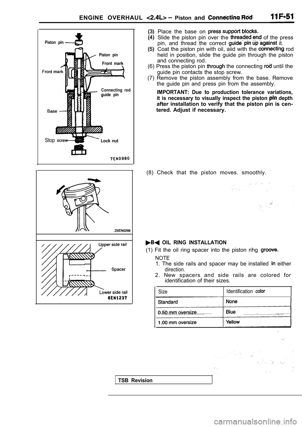
Piston pin
Piston pin
Front mark
Stop Lock nut
Connecting rod
guide pin
Place the base on
Slide the piston pin over the of the press
pin, and thread the correct
it.
Coat the piston pin with oil, aiid with the
rod
held in position, slide the guide pin through the p iston
and connecting rod. ,
(6) Press the piston pin
the connecting until the
guide pin contacts the stop screw.
(7) Remove the piston assembly from the base. Remov e
the guide pin and press pin from the assembly.
IMPORTANT: Due to production tolerance variations,
it is necessary to visually inspect the piston
depth
after installation to verify that the piston pin is cen-
tered. Adjust if necessary.
(8) Check that the piston moves. smoothly.
OIL RING INSTALLATION
(1) Fit the oil ring spacer into the piston rihg
NOTE
1. The side rails and spacer may be installed either
direction.
2. New spacers and side rails are colored for identification of their sizes.
Size Identification
TSB Revision
Page 362 of 2103
11ENGINE OVERHAUL Piston and Connecting R o d
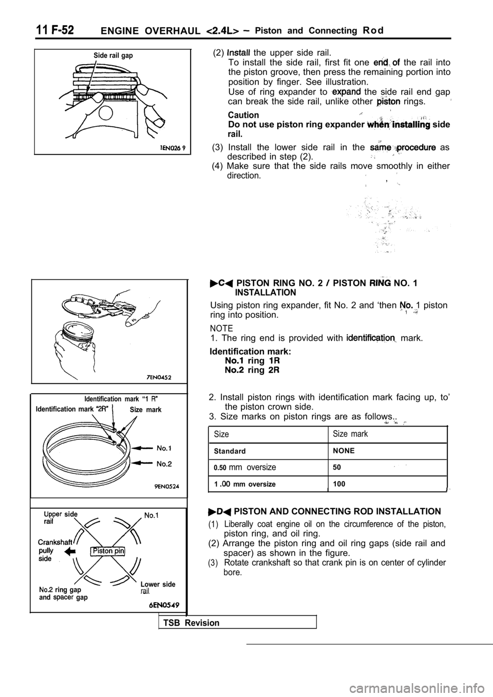
Side rail gap
9
Identification mark “1
Identification mark Size mark
side
ring gap
and gap Lower siderail
TSB Revision
(2) the upper side rail.
To install the side rail, first fit one
the rail into
the piston groove, then press the remaining portion into
position by finger. See illustration.
Use of ring expander to
the side rail end gap
can break the side rail, unlike other
rings.
Caution
Do not use piston ring expander side
rail.
(3) Install the lower side rail in the as
described in step (2).
(4) Make sure that the side rails move smoothly in either
direction.,
PISTON RING NO. 2 PISTON NO. 1
INSTALLATION
Using piston ring expander, fit No. 2 and ‘then 1 piston
ring into position.
NOTE
1. The ring end is provided with mark.
Identification mark:
ring
ring
2. Install piston rings with identification mark fa cing up, to’
the piston crown side.
3. Size marks on piston rings are as follows..
Size Size mark
StandardNONE
0.50mm oversize50
1 mm oversize100
II
PISTON AND CONNECTING ROD INSTALLATION
(1)Liberally coat engine oil on the circumference of t he piston,
piston ring, and oil ring.
(2) Arrange the piston ring and oil ring gaps (side rail and
spacer) as shown in the figure.
(3)Rotate crankshaft so that crank pin is on center of cylinder
bore.
Page 363 of 2103
ENGINE OVERHAUL Piston Rod
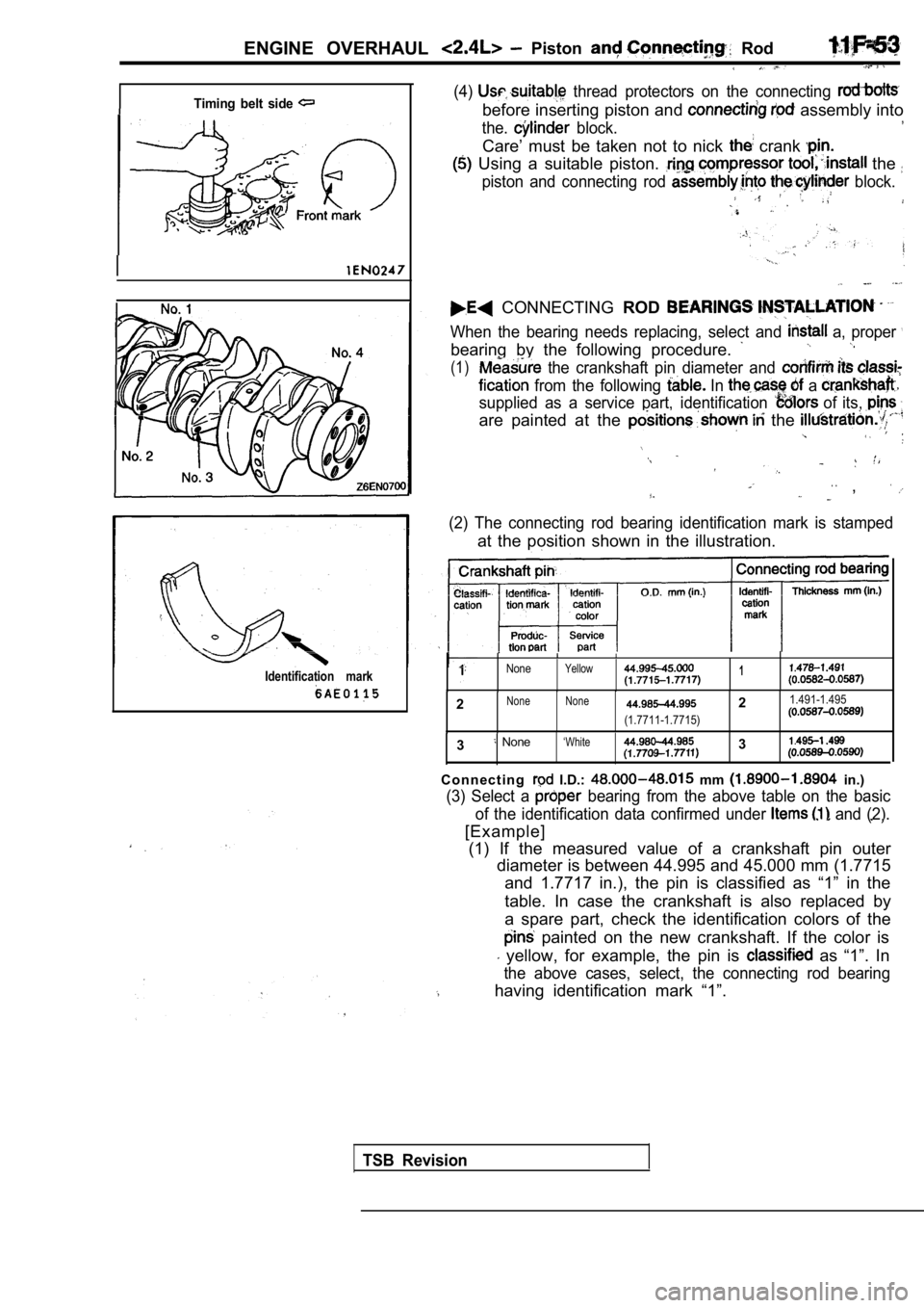
Timing belt side
Identification mark
(4) thread protectors on the connecting
before inserting piston and assembly into
the. block.
Care’ must be taken not to nick crank
Using a suitable piston. the
piston and connecting rod block.
CONNECTING ROD
When the bearing needs replacing, select and a, proper
bearing by the following procedure.
(1) the crankshaft pin diameter and
from the following In a
supplied as a service part, identification of its,
are painted at the the
. .,
(2) The connecting rod bearing identification mark is stamped
at the position shown in the illustration.
NoneYellow1
2None None21.491-1.495
(1.7711-1.7715)
3 None‘White3
C o n n e c t i n g I.D.: mm in.)
(3) Select a bearing from the above table on the basic
of the identification data confirmed under
and (2).
[Example]
(1) If the measured value of a crankshaft pin outer diameter is between 44.995 and 45.000 mm (1.7715
and 1.7717 in.), the pin is classified as “1” in th e
table. In case the crankshaft is also replaced by
a spare part, check the identification colors of th e
painted on the new crankshaft. If the color is
yellow, for example, the pin is as “1”. In
the above cases, select, the connecting rod bearing
having identification mark “1”.
TSB Revision
Page 364 of 2103
11ENGINE OVERHAUL P i s t o n
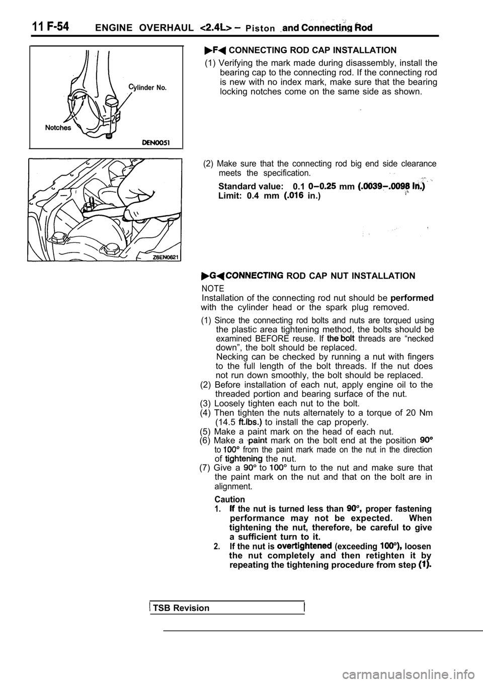
ylinder No.
CONNECTING ROD CAP INSTALLATION
(1) Verifying the mark made during disassembly, ins tall the
bearing cap to the connecting rod. If the connectin g rod
is new with no index mark, make sure that the beari ng
locking notches come on the same side as shown.
(2) Make sure that the connecting rod big end side clearance
meets the specification.
Standard value: 0.1 mm
Limit: 0.4 mm in.)
ROD CAP NUT INSTALLATION
NOTE
Installation of the connecting rod nut should be performed
with the cylinder head or the spark plug removed.
(1) Since the connecting rod bolts and nuts are tor qued using
the plastic area tightening method, the bolts should be
examined BEFORE reuse. If threads are “necked
down”, the bolt should be replaced.
Necking can be checked by running a nut with finger s
to the full length of the bolt threads. If the nut does
not run down smoothly, the bolt should be replaced.
(2) Before installation of each nut, apply engine o il to the
threaded portion and bearing surface of the nut.
(3) Loosely tighten each nut to the bolt.
(4) Then tighten the nuts alternately to a torque o f 20 Nm
(14.5
to install the cap properly.
(5) Make a paint mark on the head of each nut.
(6) Make a
mark on the bolt end at the position
to from the paint mark made on the nut in the directi on
of the nut.
(7) Give a
to turn to the nut and make sure that
the paint mark on the nut and that on the bolt are in
alignment.
Caution
1. the nut is turned less than proper fastening
performance may not be expected.When
tightening the nut, therefore, be careful to give
a sufficient turn to it.
2.If the nut is (exceeding loosen
the nut completely and then retighten it by repeating the tightening procedure from step
TSB Revision
Page 365 of 2103
ENGINE OVERHAUL Piston and Rod
INSPECTION
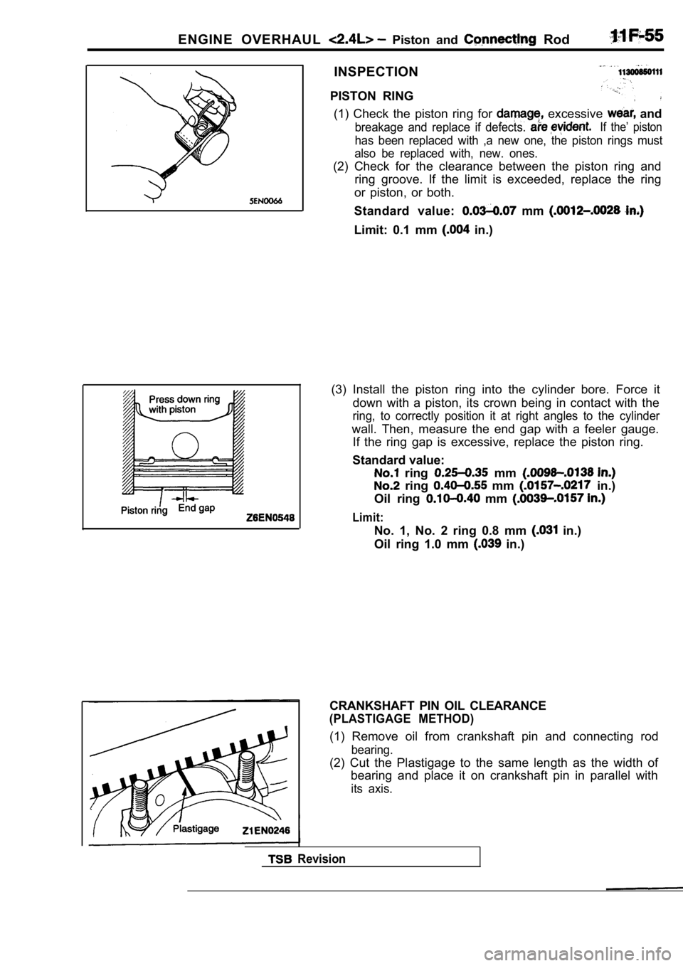
PISTON RING (1) Check the piston ring for
excessive and
breakage and replace if defects. If the’ piston
has been replaced with ,a new one, the piston rings must
also be replaced with, new. ones.
(2) Check for the clearance between the piston ring and
ring groove. If the limit is exceeded, replace the ring
or piston, or both.
Standard value:
mm
Limit: 0.1 mm in.)
(3) Install the piston ring into the cylinder bore. Force it
down with a piston, its crown being in contact with the
ring, to correctly position it at right angles to the cylinder
wall. Then, measure the end gap with a feeler gauge .
If the ring gap is excessive, replace the piston ri ng.
Standard value:
ring mm
ring mm in.)
Oil ring
mm
Limit:
No. 1, No. 2 ring 0.8 mm in.)
Oil ring 1.0 mm
in.)
Revision
CRANKSHAFT PIN OIL CLEARANCE
(PLASTIGAGE METHOD)
(1) Remove oil from crankshaft pin and connecting r od
bearing.
(2) Cut the Plastigage to the same length as the width of
bearing and place it on crankshaft pin in parallel with
its axis.
Page 366 of 2103
ENGINE OVERHAUL and
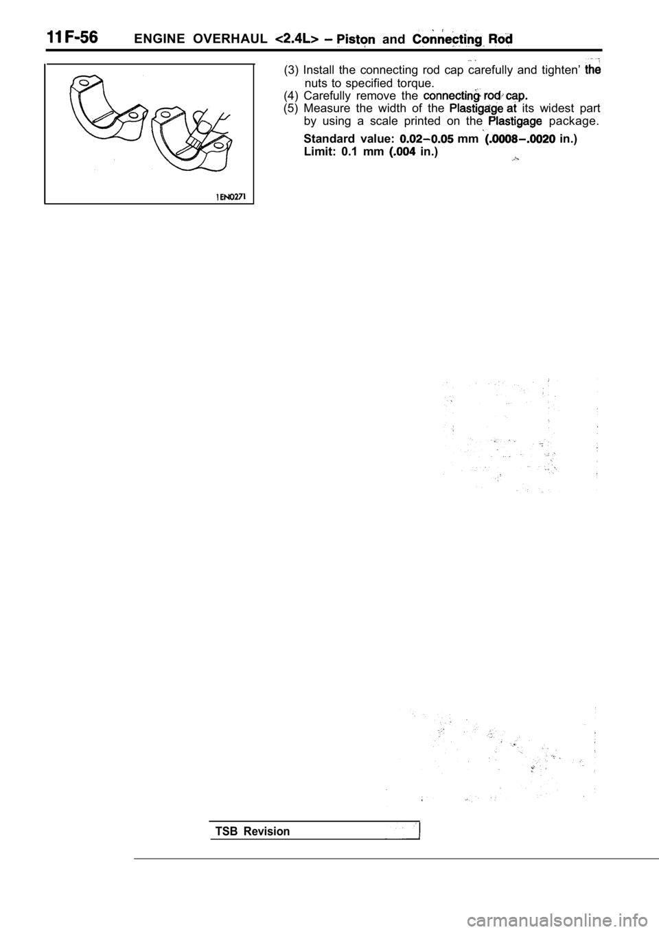
(3) Install the connecting rod cap carefully and tighten’
nuts to specified torque.
(4) Carefully remove the
(5) Measure the width of the its widest part
by using a scale printed on the
package.
Standard value:
mm in.)
Limit: 0.1 mm
in.)
TSB Revision
Page 367 of 2103
ENGINE OVERHAUL Crankshaft, Flywheel and Plate
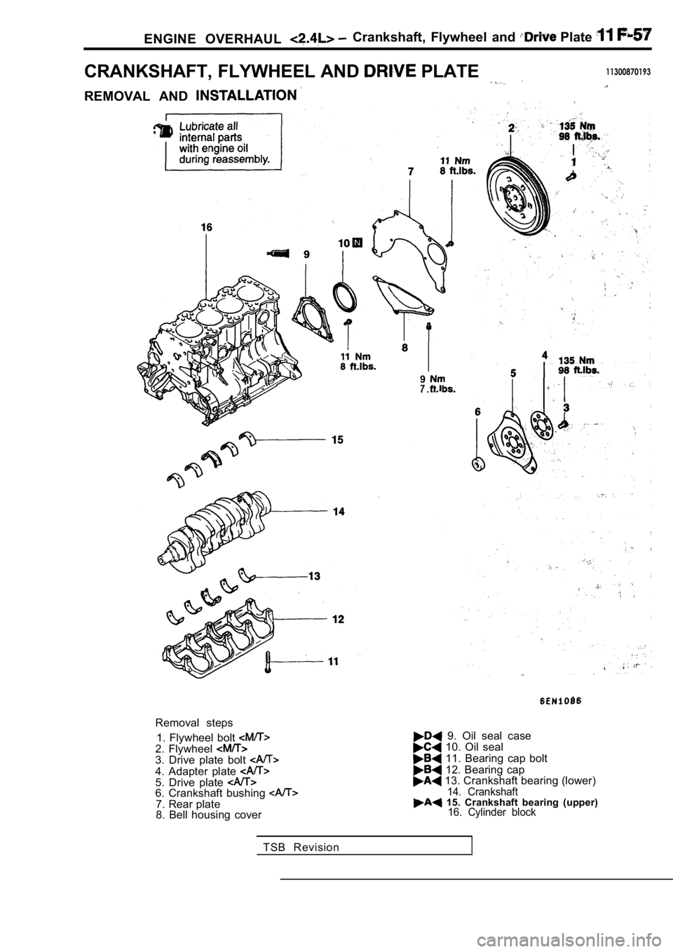
CRANKSHAFT, FLYWHEEL AND PLATE11300870193
REMOVAL AND
97
Removal steps1. Flywheel bolt
2. Flywheel 3. Drive plate bolt
4. Adapter plate 5. Drive plate 6. Crankshaft bushing 7. Rear plate
8. Bell housing cover
9. Oil seal case 10. Oil seal
11. Bearing cap bolt
12. Bearing cap 13. Crankshaft bearing (lower)14. Crankshaft 15. Crankshaft bearing (upper)16. Cylinder block
TSB Revision
Page 368 of 2103
ENGINE OVERHAUL Crankshaft,
Timing belt side
Cylinder block bearing boreidentification mark
Lower bearing No.
Identification
mark
Upper bearing (for No.
Identification
mark
1
SERVICE
CRANKSHAFT BEARING
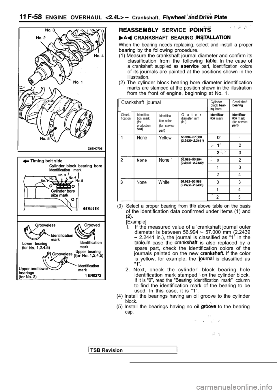
When the bearing needs replacing, select and instal l a proper
bearing by the following procedure.
(1) Measure the crankshaft journal diameter and con firm its
classification from the following
In the case of
a crankshaft supplied as part, identification colors
of its journals are painted at the positions shown in the
illustration.
(2) The cylinder block bearing bore diameter identi fication
marks are stamped at the position shown in the illustration
from the front of engine, beginning at No. 1.
Crankshaft journal
Classi-
fication Identifica-
tion mark
(for
production
None
NoneNone
Identifica-
tion color
(for service
Yellow
WhiteNone
1
2
3
02
13
2
4
03
14
25
(3)Select a proper bearing from above table on the basis
of the identification data confirmed under Items (1 ) and
[Example]
1.If the measured value of a ‘crankshaft journal oute r
diameter is between 56.994
57.000 mm (2.2439
2.2441 in.), the journal is classified as “1” in t he
case the is also replaced by a
spare part, check the identification colors of the
journals painted on the new
If the color
is yellow, for example, the
is classified as
.
2. Next, check the cylinder’ block bearing hole identification mark stamped
the cylinder block.
If it is read the ideritification mark” column
to find the identification mark of the bearing to b e
used. In this case, it is “1”.
(4) Install the bearings having an oil groove to th e cylinder
block.
(5) Install the bearings having no oil to the bearing
cap.
.
O u t e rdiameter mm
(in.)
Cylinder
block
bore
mark
Crankshaft
mark(for service
TSB Revision
Page 369 of 2103
E N G I N E O V E R H A U L Flywheel
S h a n k l e n g t h
Arrow
CAP B E A R I N G C A P B O L T
INSTALLATION
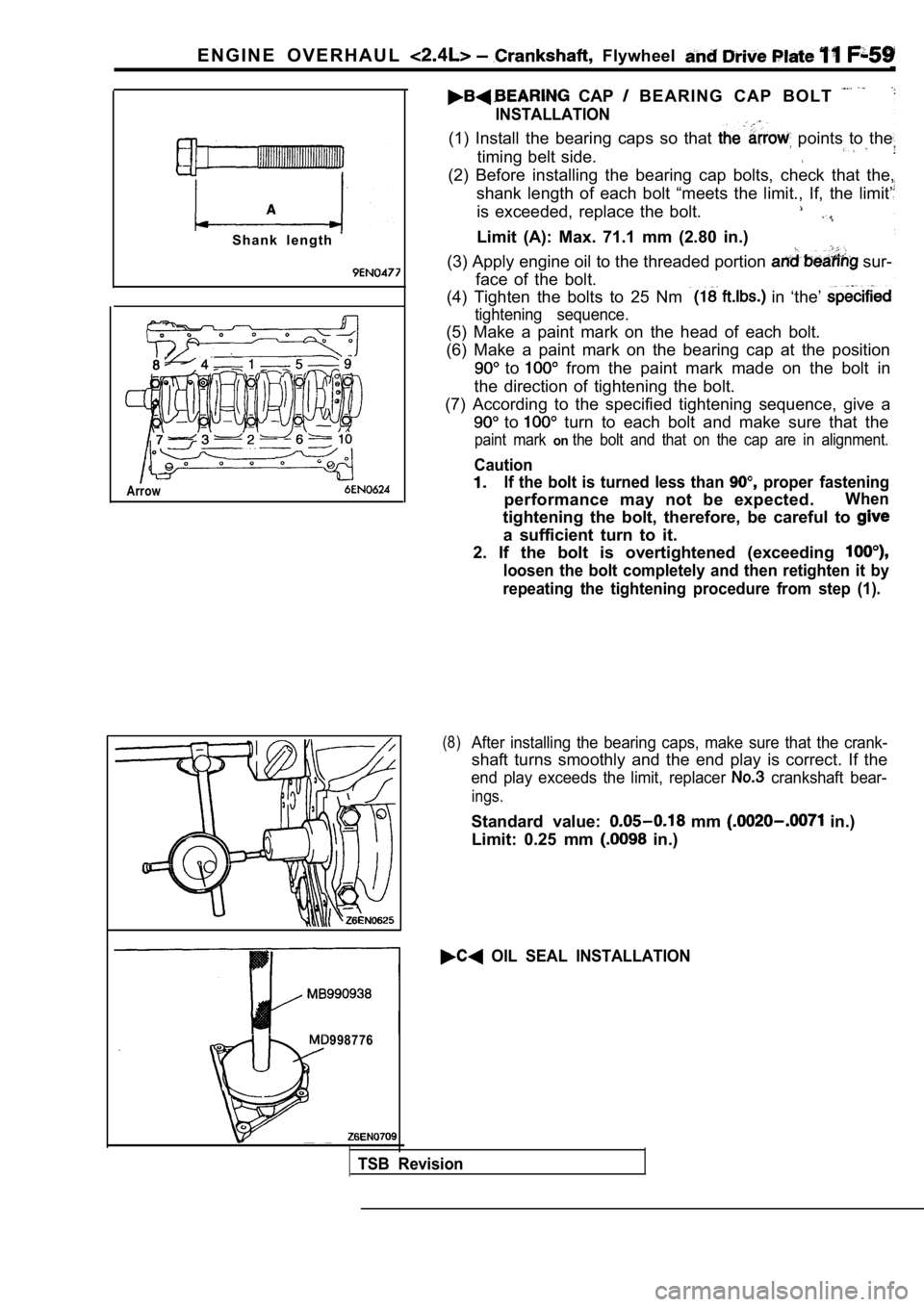
(1) Install the bearing caps so that points to the
timing belt side.
(2) Before installing the bearing cap bolts, check that the,
shank length of each bolt “meets the limit., If, th e limit’
is exceeded, replace the bolt.
Limit (A): Max. 71.1 mm (2.80 in.)
(3) Apply engine oil to the threaded portion
sur-
face of the bolt.
(4) Tighten the bolts to 25 Nm
in ‘the’
tightening sequence.
(5) Make a paint mark on the head of each bolt.
(6) Make a paint mark on the bearing cap at the pos ition
to from the paint mark made on the bolt in
the direction of tightening the bolt.
(7) According to the specified tightening sequence, give a
to turn to each bolt and make sure that the
paint mark onthe bolt and that on the cap are in alignment.
Caution
If the bolt is turned less than proper fastening
performance may not be expected.When
tightening the bolt, therefore, be careful to
a sufficient turn to it.
2. If the bolt is overtightened (exceeding
loosen the bolt completely and then retighten it by
repeating the tightening procedure from step (1).
(8)After installing the bearing caps, make sure that t he crank-
shaft turns smoothly and the end play is correct. I f the
end play exceeds the limit, replacer crankshaft bear-
ings.
Standard value: mm in.)
Limit: 0.25 mm
in.)
OIL SEAL INSTALLATION
998776
TSB Revision
Page 370 of 2103
ENGINE O V E R H A U L Crankshaft. Drive
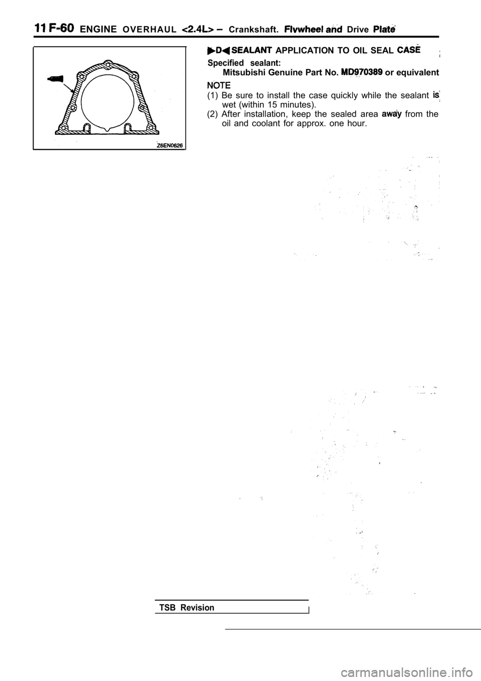
APPLICATION TO OIL SEAL
Specified sealant:
Mitsubishi Genuine Part No. or equivalent
(1) Be sure to install the case quickly while the s ealant
wet (within 15 minutes).
(2) After installation, keep the sealed area
from the
oil and coolant for approx. one hour.
TSB RevisionI