MITSUBISHI SPYDER 1990 Service Repair Manual
Manufacturer: MITSUBISHI, Model Year: 1990, Model line: SPYDER, Model: MITSUBISHI SPYDER 1990Pages: 2103, PDF Size: 68.98 MB
Page 351 of 2103
Front Case,
E N G I N E Shaft
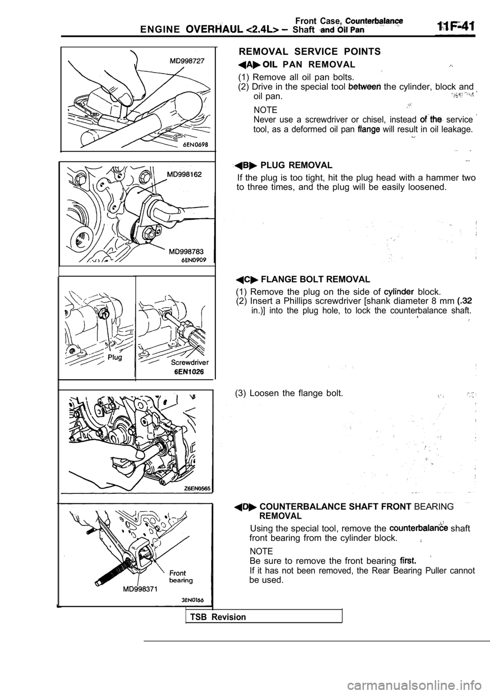
REMOVAL SERVICE POINTS
PAN REMOVAL
(1) Remove all oil pan bolts.
(2) Drive in the special tool
the cylinder, block and
oil pan.
NOTE
Never use a screwdriver or chisel, instead service
tool, as a deformed oil pan will result in oil leakage.
PLUG REMOVAL
If the plug is too tight, hit the plug head with a hammer two
to three times, and the plug will be easily loosene d.
FLANGE BOLT REMOVAL
(1) Remove the plug on the side of
block.
(2) Insert a Phillips screwdriver [shank diameter 8 mm
in.)] into the plug hole, to lock the counterbalanc e shaft.,
(3) Loosen the flange bolt.
COUNTERBALANCE SHAFT FRONT BEARING
REMOVAL
Using the special tool, remove the shaft
front bearing from the cylinder block.
NOTE
Be sure to remove the front bearing
If it has not been removed, the Rear Bearing Puller cannot
be used.
TSB Revision
Page 352 of 2103
Front Case, ENGINE OVERHAUL Shaft and
603
Rear
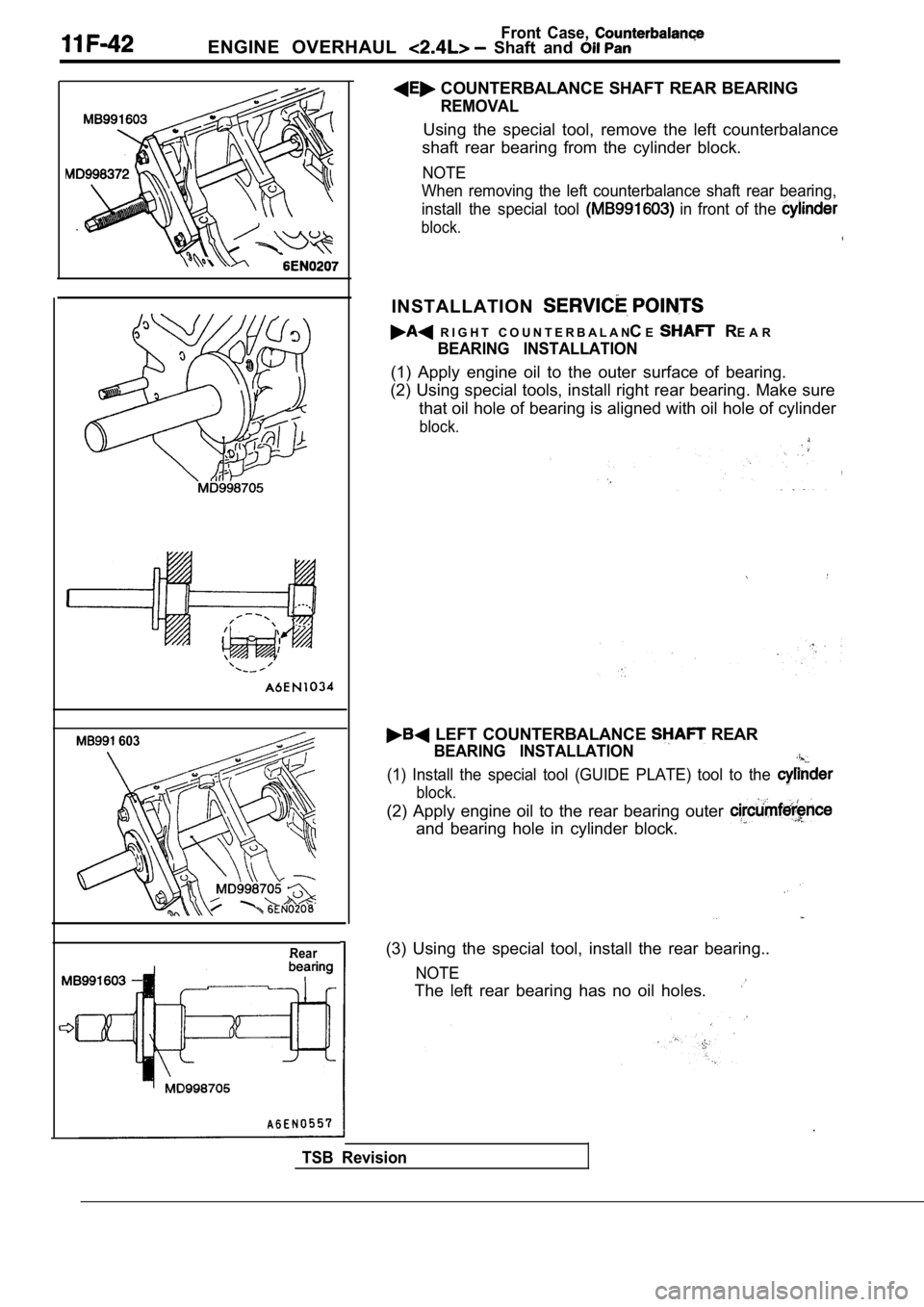
COUNTERBALANCE SHAFT REAR BEARING
REMOVAL
Using the special tool, remove the left counterbalance
shaft rear bearing from the cylinder block.
NOTE
When removing the left counterbalance shaft rear be aring,
install the special tool
in front of the
block.
INSTALLATION
R I G H T C O U N T E R B A L A N CE R E A R
BEARING INSTALLATION
(1) Apply engine oil to the outer surface of bearin g.
(2) Using special tools, install right rear bearing . Make sure
that oil hole of bearing is aligned with oil hole o f cylinder
block.
LEFT COUNTERBALANCE REAR
BEARING INSTALLATION
(1) Install the special tool (GUIDE PLATE) tool to the
block.
(2) Apply engine oil to the rear bearing outer
and bearing hole in cylinder block.
(3) Using the special tool, install the rear bearing..
NOTE
The left rear bearing has no oil holes.
TSB Revision
Page 353 of 2103
Front Case,
ENGINE OVERHAUL Shaft and
Socket wrench
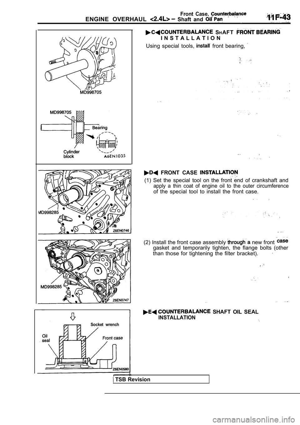
SHAFT
I N S T A L L A T I O N
Using special tools,
front bearing,
FRONT CASE
(1) Set the special tool on the front end of cranks haft and
apply a thin coat of engine oil to the outer circum ference
of the special tool to install the front case.
(2) Install the front case assembly new front
gasket and temporarily tighten, the flange bolts (o ther
than those for tightening the filter bracket).
SHAFT OIL SEAL
INSTALLATION
TSB Revision
Page 354 of 2103
11ENGINE OVERHAUL Shaft and
Front Case, Counterbalance
Socket
gnment
- -
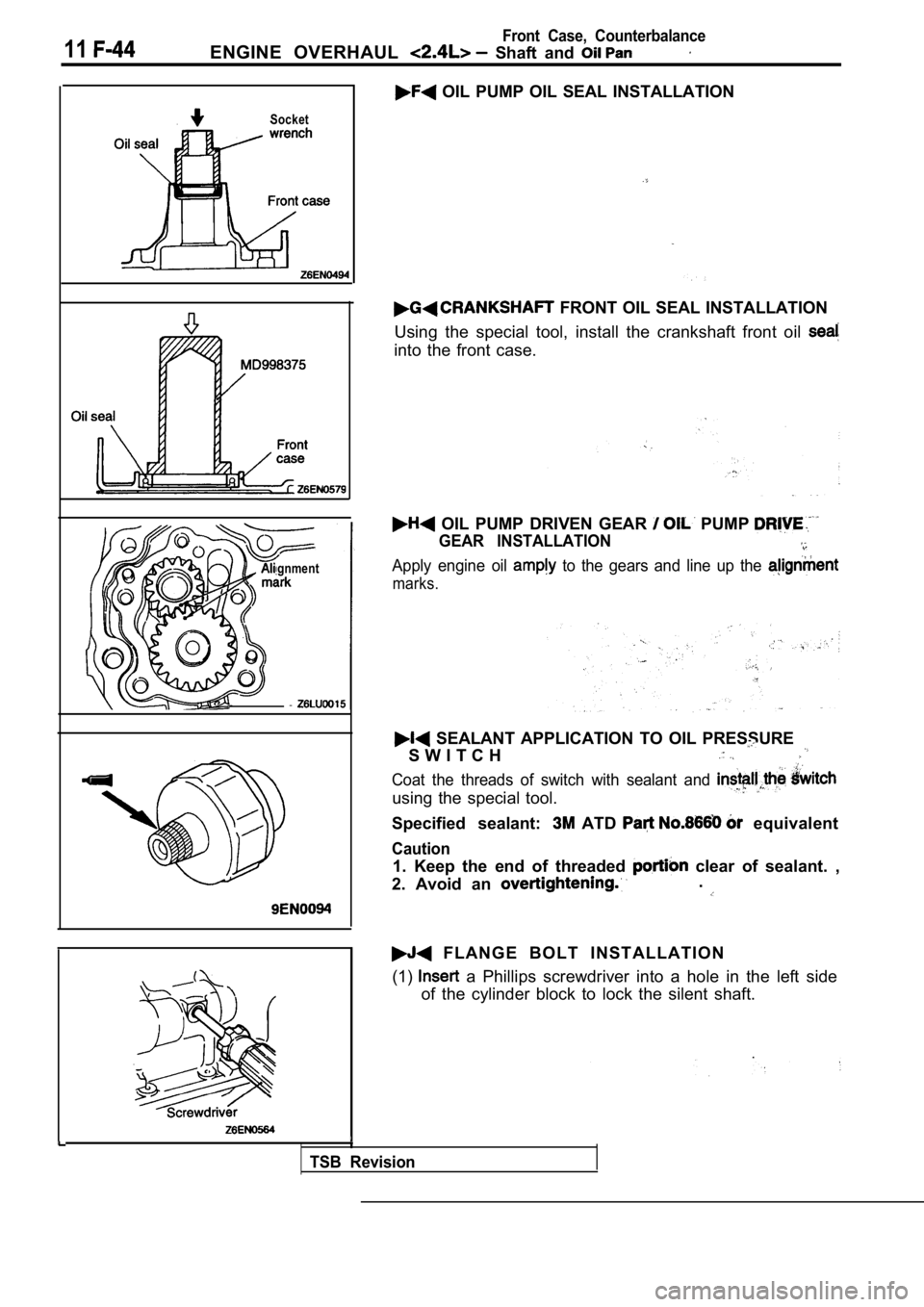
OIL PUMP OIL SEAL INSTALLATION
FRONT OIL SEAL INSTALLATION
Using the special tool, install the crankshaft fron t oil
into the front case.
OIL PUMP DRIVEN GEAR PUMP
GEAR INSTALLATION
Apply engine oil to the gears and line up the
marks.
SEALANT APPLICATION TO OIL PRESSURE
S W I T C H
Coat the threads of switch with sealant and
using the special tool.
Specified sealant: ATD equivalent
Caution
1. Keep the end of threaded clear of sealant. ,
2. Avoid an .
F L A N G E B O L T I N S T A L L A T I O N
(1)
a Phillips screwdriver into a hole in the left sid e
of the cylinder block to lock the silent shaft.
TSB Revision
Page 355 of 2103
ENGINE OVERHAUL Shaft and Can
Case,
62
Crank pulley side
0
mm bolts
0
Oil pan viewed from lower side
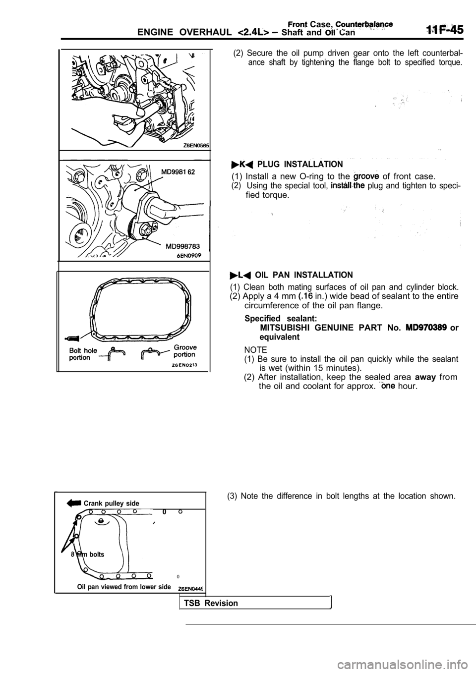
(2) Secure the oil pump driven gear onto the left counterbal-
ance shaft by tightening the flange bolt to specified torque.
PLUG INSTALLATION
(1) Install a new O-ring to the of front case.
(2)Using the special tool, plug and tighten to speci-
fied torque.
OIL PAN INSTALLATION
(1) Clean both mating surfaces of oil pan and cylin der block.
(2) Apply a 4 mm in.) wide bead of sealant to the entire
circumference of the oil pan flange.
Specified sealant:
MITSUBISHI GENUINE PART No. or
equivalent
NOTE
(1) Be sure to install the oil pan quickly while th e sealant
is wet (within 15 minutes).
(2) After installation, keep the sealed area awayfrom
the oil and coolant for approx.
hour.
(3) Note the difference in bolt lengths at the loca tion shown.
TSB Revision
Page 356 of 2103
Front Case,
ENGINE OVERHAUL Shaft
Drain pigasket
side
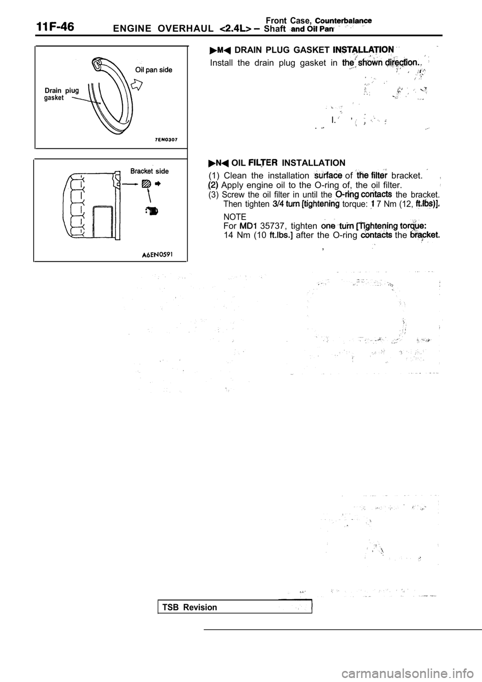
DRAIN PLUG GASKET
Install the drain plug gasket in
. .
, I..
OIL INSTALLATION
(1) Clean the installation
of bracket.
Apply engine oil to the O-ring of, the oil filter.
(3) Screw the oil filter in until the the bracket.
Then tighten
torque: 7 Nm (12,
NOTE
For 35737, tighten
14 Nm (10 after the O-ring the
,
TSB Revision
Page 357 of 2103
Front
ENGINE OVERHAUL Shaft and
I N S P E C T I O N
FRONT CASE
(1) Check oil holes for clogging and -clean if nece ssary.
(2) Check left counterbalance shaft front bearing
wear, damage and seizure. If there is anything ‘wro ng
with the section, replace the front case.
(3) Check the front case for cracks and other ‘dama ge. Re-
place cracked or damaged front case.
OIL SEAL
(1) Check the oil seal lip for wear and damage. Replace
oil seal if necessary.
(2) Check the
seal lip for deterioration. Replace oil seal
if necessary.
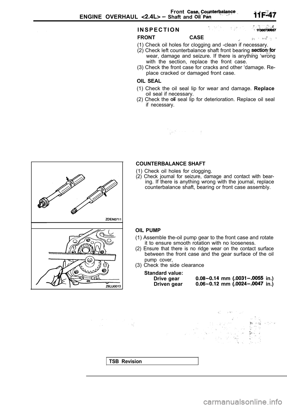
COUNTERBALANCE SHAFT
(1) Check oil holes for clogging.
(2) Check journal for seizure, damage and contact w ith bear-
ing. If there is anything wrong with the journal, replace
counterbalance shaft, bearing or front case assembl y.
OIL PUMP
(1) Assemble the-oil pump gear to the front case an d rotate
it to ensure smooth rotation with no looseness.
(2) Ensure that there is no ridge wear on the conta ct surface
between the front case and the gear surface of the oil
pump cover,
(3) Check the side clearance
Standard value: Drive gear
mm in.)
Driven gear
mm in.)
TSB Revision
Page 358 of 2103
ENGINE OVERHAUL Piston and Connecting Rod
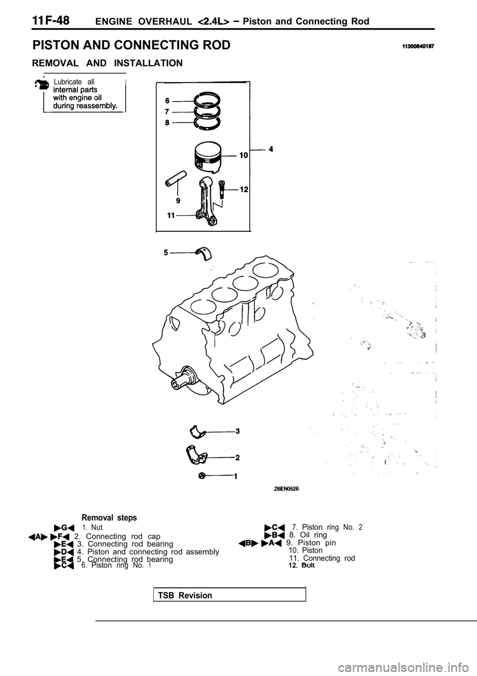
PISTON AND CONNECTING ROD
REMOVAL AND INSTALLATION
Lubricate allI
Removal steps
1.Nut
2. Connecting rod cap 3. Connecting rod bearing 4. Piston and connecting rod assembly 5. Connecting rod bearing6.Pistonring No.1
7.Pistonring No.2 8. Oil ring 9. Piston pin10. Piston 11. Connecting rod
12.
TSB Revision
Page 359 of 2103
ENGINE OVERHAUL Piston and
number
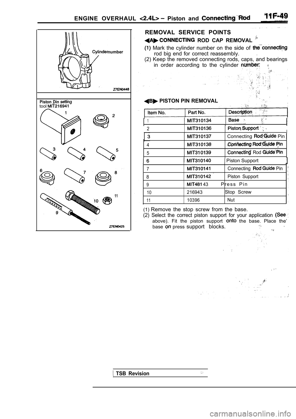
Piston Din tool
11
REMOVAL SERVICE POINTS
ROD CAP REMOVAL
Mark the cylinder number on the side of
rod big end for correct reassembly..
(2) Keep the removed connecting rods, caps, and bearings
in order according to the cylinder
PISTON PIN REMOVAL
1
2I Connecting Pin
4
5 Rod
Piston Support
7Connecting Pin
8
Piston Support
9 43P r e s s P i n
10216943Stop Screw
1110396Nut
(1) Remove the stop screw from the base.
(2) Select the correct piston support for your appl ication
above). Fit the piston support the base. Place the’
base
press support blocks.
TSB Revision
Page 360 of 2103
ENGINE OVERHAUL Piston and Rod
TSB Revision
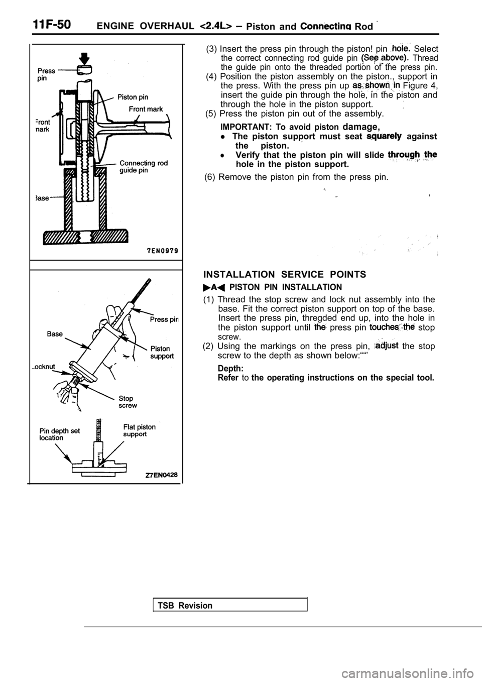
(3) Insert the press pin through the piston! pin Select
the correct connecting rod guide pin Thread
the guide pin onto the threaded portion of the pres s pin.
(4) Position the piston assembly on the piston., support in
the press. With the press pin up
Figure 4,
insert the guide pin through the hole, in the pisto n and
through the hole in the piston support.
(5) Press the piston pin out of the assembly.
IMPORTANT: To avoid piston damage,
l The piston support must seat against
the piston.
lVerify that the piston pin will slide
hole in the piston support.
(6) Remove the piston pin from the press pin.
,
INSTALLATION SERVICE POINTS
PISTON PIN INSTALLATION
(1) Thread the stop screw and lock nut assembly int o the
base. Fit the correct piston support on top of the base.
Insert the press pin, thregded end up, into the hol e in
the piston support until
press pin stop
screw.
(2) Using the markings on the press pin, the stop
screw to the depth as shown below:““’
Depth:
Refer
tothe operating instructions on the special tool.