MITSUBISHI SPYDER 1990 Service Repair Manual
Manufacturer: MITSUBISHI, Model Year: 1990, Model line: SPYDER, Model: MITSUBISHI SPYDER 1990Pages: 2103, PDF Size: 68.98 MB
Page 391 of 2103
ON-BOARD DIAGNOSTICS
The
Control Module (PCM) monitors
many different circuits in the fuel injection syste m.
If the PCM senses a problem with a monitored
circuit often enough to indicate an actual problem,
it stores a diagnostic trouble code in the
memory.
After the PCM first detects a malfunction, a
diagnostic trouble code is recorded when the engine
i s r e s t a r t e d a n d t h e s a m e m a l f u n c t i o n i s
re-defected. However, for items marked with a
a diagnostic trouble code is recorded the
first detection of the malfunction.
After that, if the PCM does not re-detect the
malfunction for 40 drives* (51 engine start for
non-emission related faults), the diagnostic troubl e
code will be erased from the PCM memory.
NOTE
A drive indicates from engine start to stop and
monitors the power train component.
However, for misfiring or a fuel system rich/lean,
the diagnostic trouble codes will be erased under
the following conditions.
lWhen driving conditions (engine speed, engine
coolant temperature, etc.) are similar, to those
when the malfunction was first recorded.
l When the PCM does not re-detect the
malfunction for 80 drives*.
Technicians can display stored diagnostic trouble
codes by two different methods.
ENGINE (NON-TURBO)> Troubleshooting
The first is to cycle the ignition switch
On-Off-On-Off-On within 5
Then count
the number of times the malfunction indicator lamp
(check engine lamp) on the instrument panel flashes
on and off. The number of flashes represents the
diagnostic trouble code. There is a slight pause
between the flashes representing the first and
second digits of the code. Longer pauses separate
individual trouble codes. The second method of
reading diagnostic trouble codes uses
scan
Connect the scan tool to the
(diagnostic) connector in the vehicle.
FREEZE FRAME DATA
The PCM records the diagnostic trouble code and
also the engine operating conditions the time
the malfunction was detected. are called
“freeze frame” data.
This data indicates the engine operating condition
from when nothing at all is the initial
detection of the
However, misfiring
or fuel trim malfunction data are always. replaced
with the latest data.
This data can be read by using the scan tool, and
can then be used in simulation tests for
troubleshooting.
Data items are as follows.
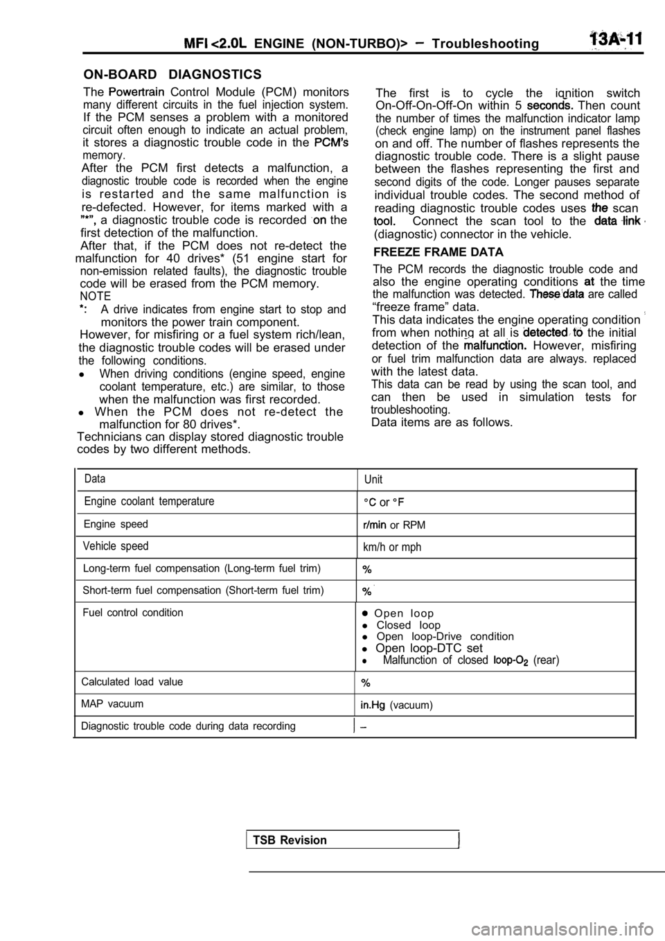
DataUnit
Engine coolant temperature
Engine speed
Vehicle speed
or
or RPM
km/h or mph
Long-term fuel compensation (Long-term fuel trim)
Short-term fuel compensation (Short-term fuel trim)
Fuel control condition O p e n l o o p
l Closed loop
l Open loop-Drive condition
l Open loop-DTC set
lMalfunction of closed (rear)
Calculated load value
MAP vacuum
(vacuum)
Diagnostic trouble code during data recording
TSB Revision
Page 392 of 2103
ENGINE (NON-TURBO)> Troubleshooting.
HOW TO READ AND ERASE DIAGNOSTIC
CODES
TSB Revision Caution
1. If battery voltage is diagnostic codes.
may not be output. Be sure to check the,
and charging system before
2.If the battery is disconnected or if the connector
is disconnected, the diagnostic trouble code
will be erased. Do not disconnect the battery or
until after the diagnostic are recorded.
3. Turn the ignition switch, off before
disconnecting the scan. tool.
When using the scan tool
NOTE
When carrying out inspection General ‘Scan Tool,
mode, the interface
cartridge) and
adaptor harness do not
need to be installed.
2.The following items cannot be checked in scan
mode; they can only be checked in General Scan
Tool mode.
SENSOR READ TEST
l term fuel trim
l Calculated load vlaue
FREEZ FRAME DATA
READINESS TESTS
3. When diagnostic trouble codes (DTC) are’ erased,
the freeze frame data and
test status will
be erased at the same time. Therefore,
should be recorded if necessary
4. If the automatic transaxle DTC
been stored, the DTC for the PCM should be
after the DTC for the TCM is erased:
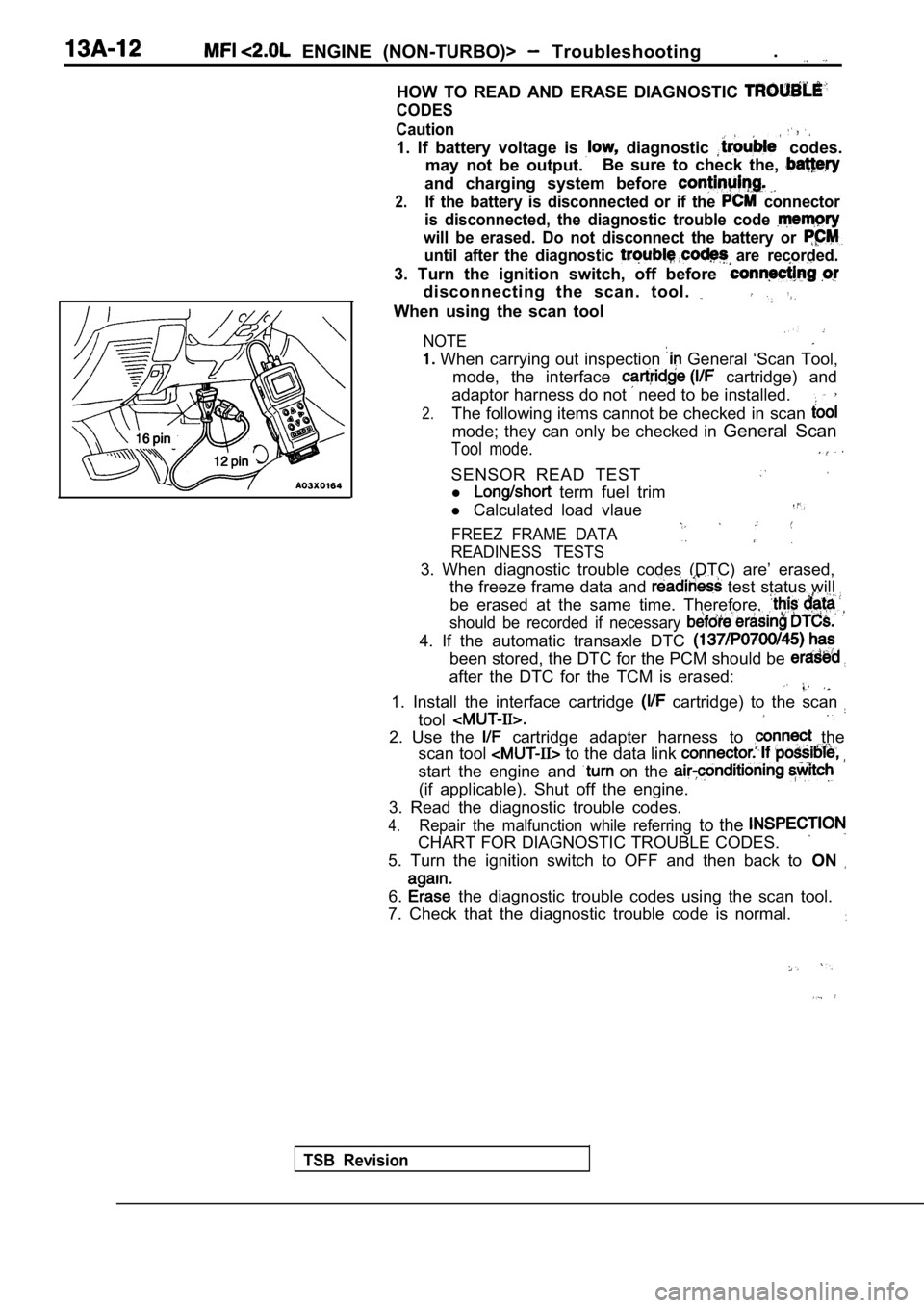
1. Install the interface cartridge cartridge) to the scan
tool
2. Use the cartridge adapter harness to the
scan tool
to the data link
start the engine and on the
(if applicable). Shut off the engine.
3. Read the diagnostic trouble codes.
4.Repair the malfunction while referring to the
CHART FOR DIAGNOSTIC TROUBLE CODES.
5. Turn the ignition switch to OFF and then back to ON
6. the diagnostic trouble codes using the scan tool.
7. Check that the diagnostic trouble code is normal .
Page 393 of 2103
ENGINE (NON-TURBO)> Troubleshooting 3
If scan tool not available
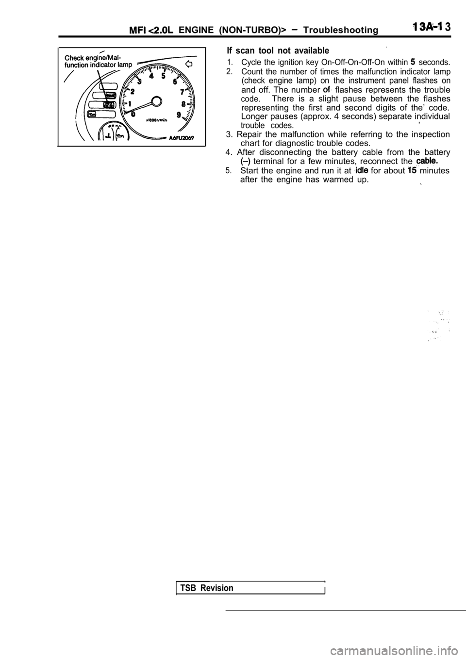
1.Cycle the ignition key On-Off-On-Off-On within seconds.
2.Count the number of times the malfunction indicator lamp
(check engine lamp) on the instrument panel flashes on
and off. The number flashes represents the trouble
code.There is a slight pause between the flashes
representing the first and second digits of the’ co de.
Longer pauses (approx. 4 seconds) separate individu al
,
trouble codes.
3. Repair the malfunction while referring to the in spection
chart for diagnostic trouble codes.
4. After disconnecting the battery cable from the b attery
terminal for a few minutes, reconnect the
5.Start the engine and run it at for about minutes
after the engine has warmed up.
TSB RevisionI
Page 394 of 2103
ENGINE (NON-TURBO)>
LEAK DETECTION PUMP MONITOR
Related diagnosis trouble codes (DTC)
l EVAP leak monitor small leak detected
l
EVAP leak monitor large leak detected
l
EVAP leak monitor pinched hose found
Operation
The leak detection assembly incorporates two primar y functions: it must detect a the
system and seal the evaporative system so the leak detection test can be run.. .
The’ primary components within the assembly are: A three port solenoid activates ‘both of the
functions listed above; a pump which contains a swi tch; two check valves and a spring/diaphragm, a’
canister vent valve (CVV) seal which contains a spr ing loaded vent seal valve.
Immediately after a cold start, between predetermin ed temperature thresholds limits, the three port
solenoid is briefly energized. This initializes the pump by drawing air into the pump cavity and also closes
the vent seal. During non test conditions the vent seal is held open by the pump diaphragm assembly
which pushes it open at the full travel position. The vent seal will remain closed while the pump is c ycling
due to the reed switch triggering of the three port solenoid that prevents the diaphragm assembly from
reaching full travel. After the brief initializatio n period, the solenoid is de-energized allowing atm ospheric
pressure to enter the pump cavity, thus permitting the spring to drive the diaphragm which forces air
out of the pump cavity and into the vent system. Wh en the solenoid is energized and de-energized,
the cycle is repeated creating flow in typical diaphragm pump fashion. The pump is controlled in 2 mod es:
Pump Mode: The pump is cycled at a fixed rate to achieve a rapid pressure build in order to shorten
the overall test length.
Test Mode: The solenoid is energized with a fixed d uration pulse. Subsequent fixed pulses occur
when the diaphragm reaches the Switch closure point .
The spring in the pump is set so that the system wi ll achieve an equalized pressure of about 7.5”
The cycle rate of pump strokes is quite rapid as the system begins to pump up to this pressure.
As the pressure
the cycle rate starts to drop off. If there is no leak in the system, the pump
would eventually stop pumping at the equalized pres sure. If there is a leak, it will continue to pump
at a rate representative of the flow characteristic of the size of the leak. From this information we can
determine if the leak is larger than the required d etection limit (currently set at
orifice by CARB).
If a leak is revealed during the leak test portion of the test, the test is terminated at the end of the
mode and no further system checks will be performed .
After passing the leak detection phase of the test, system pressure is maintained by turning on the
solenoid until the purge system is activated. Purg e activation in effect creates a leak. The cycle
rate is again interrogated and when it increases du e to the flow through the purge system, the leak
check portion of the diagnostic is complete.
The canister vent valve will unseal the system afte r completion of the test sequence as the pump
diaphragm assembly moves to the full travel positio n.
Evaporative system functionality will be verified b y using the stricter evap purge flow monitor. At an
appropriate warm idle the LDP will be energized to seal the canister vent. The purge flow will be clocked
up from some small value in an attempt to see a shi ft in the 02 control system. If fuel vapor, indicated
by a shift in the 02 control, is present the test i s passed. If not, it is assumed that the purge syst em
is not functioning in some respect. The LDP is agai n turned off and the test is ended.
TSB Revision
Page 395 of 2103
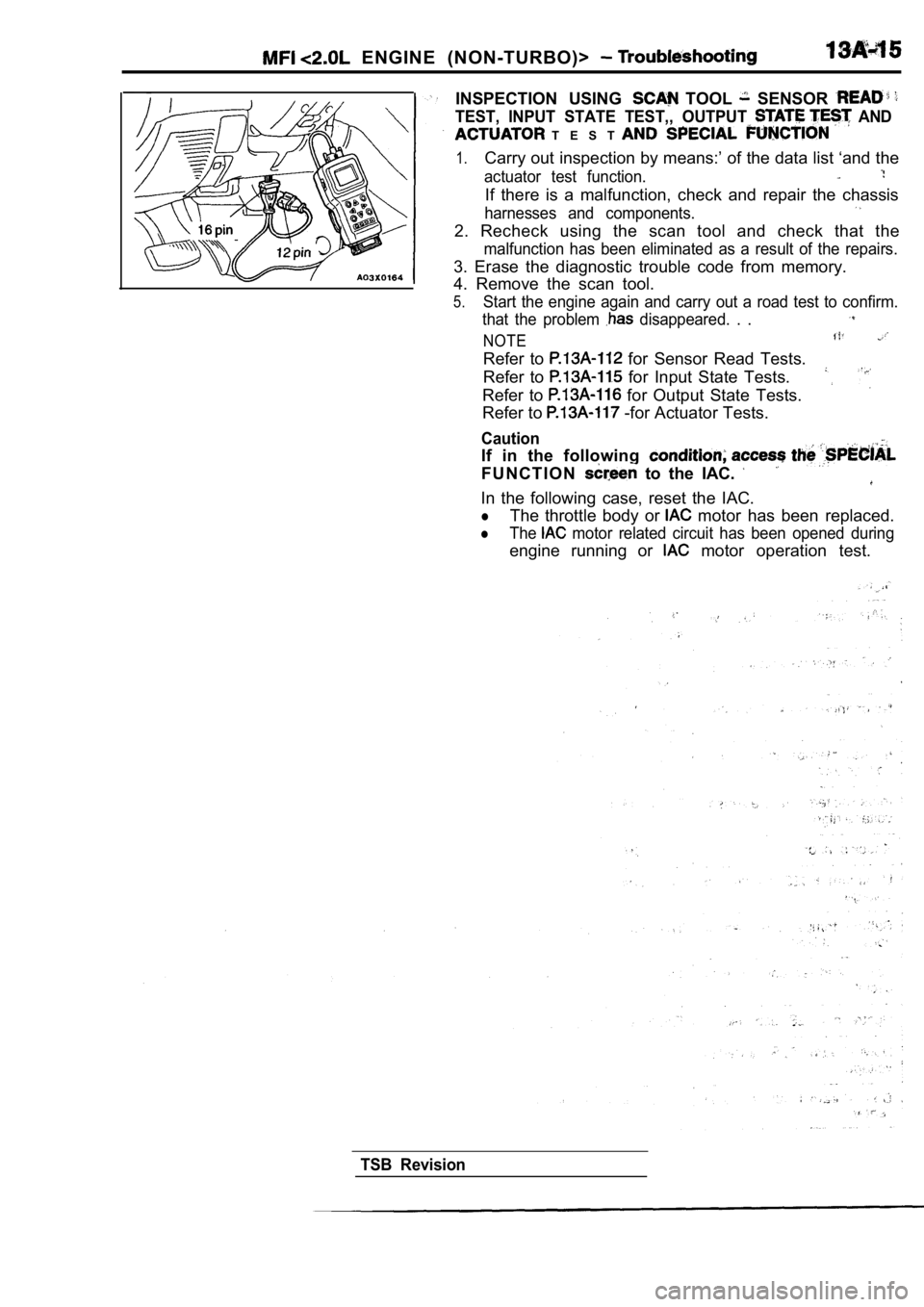
ENGINE (NON-TURBO)>
INSPECTION USING TOOL SENSOR
TEST, INPUT STATE TEST,, OUTPUT AND
T E S T
1.Carry out inspection by means:’ of the data list ‘and the
actuator test function.
If there is a malfunction, check and repair the cha ssis
harnesses and components.
2. Recheck using the scan tool and check that the
malfunction has been eliminated as a result of the repairs.
3. Erase the diagnostic trouble code from memory.
4. Remove the scan tool.
5.Start the engine again and carry out a road test to confirm.
that the problem
disappeared. . .
NOTE
Refer to for Sensor Read Tests.
Refer to
for Input State Tests.
Refer to
for Output State Tests.
Refer to -for Actuator Tests.
Caution
If in the following
F U N C T I O N to the IAC.
In the following case, reset the IAC.
lThe throttle body or motor has been replaced.
lThe motor related circuit has been opened during
engine running or motor operation test.
TSB Revision
Page 396 of 2103
ENGINE (NON-TURBO)> Troubleshooting
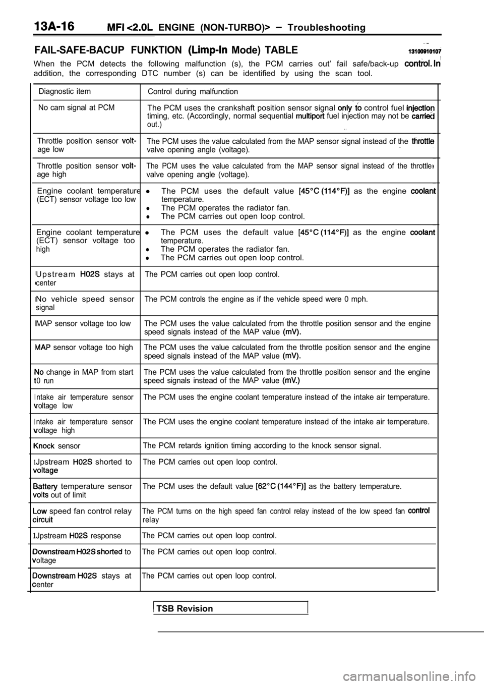
FAIL-SAFE-BACUP FUNKTION Mode) TABLE
When the PCM detects the following malfunction (s), the PCM carries out’ fail safe/back-up
addition, the corresponding DTC number (s) can be i dentified by using the scan tool.
I
I
I
I
I
1
1
Diagnostic item
Control during malfunction
No cam signal at PCM
The PCM uses the crankshaft position sensor signal control fuel timing, etc. (Accordingly, normal sequential fuel injection may not be
out.)
Throttle position sensor The PCM uses the value calculated from the MAP sens or signal instead of the age low
valve opening angle (voltage).
Throttle position sensor The PCM uses the value calculated from the MAP sens or signal instead of the throttle
age high
valve opening angle (voltage).
Engine coolant temperature l
The PCM uses the default value as the engine
(ECT) sensor voltage too low temperature.
lThe PCM operates the radiator fan.
lThe PCM carries out open loop control.
Engine coolant temperature lThe PCM uses the default value
as the engine
(ECT) sensor voltage tootemperature.
highlThe PCM operates the radiator fan.
lThe PCM carries out open loop control.
U p s t r e a m
stays atThe PCM carries out open loop control.
center
No vehicle speed sensorThe PCM controls the engine as if the vehicle speed were 0 mph.
signal
MAP sensor voltage too low The PCM uses the value ca lculated from the throttle position sensor and the engine
speed signals instead of the MAP value
sensor voltage too high The PCM uses the value calc ulated from the throttle position sensor and the engine
speed signals instead of the MAP value
change in MAP from start The PCM uses the value cal culated from the throttle position sensor and the engine
0 runspeed signals instead of the MAP value
ntake air temperature sensorThe PCM uses the engine coolant temperature instead of the intake air temperature.
roltage low
ntake air temperature sensor
The PCM uses the engine coolant temperature instead of the intake air temperature.
roltage high
sensorThe PCM retards ignition timing according to the kn
ock sensor signal.
Jpstream shorted toThe PCM carries out open loop control.
temperature sensorThe PCM uses the default value as the battery temperature.
out of limit
speed fan control relayThe PCM turns on the high speed fan control relay i nstead of the low speed fan
relay
Jpstream responseThe PCM carries out open loop control.
to The PCM carries out open loop control.
oltage
stays atThe PCM carries out open loop control.
enter
TSB Revision
Page 397 of 2103
ENGINE (NON-TURBO)> Troubleshooting
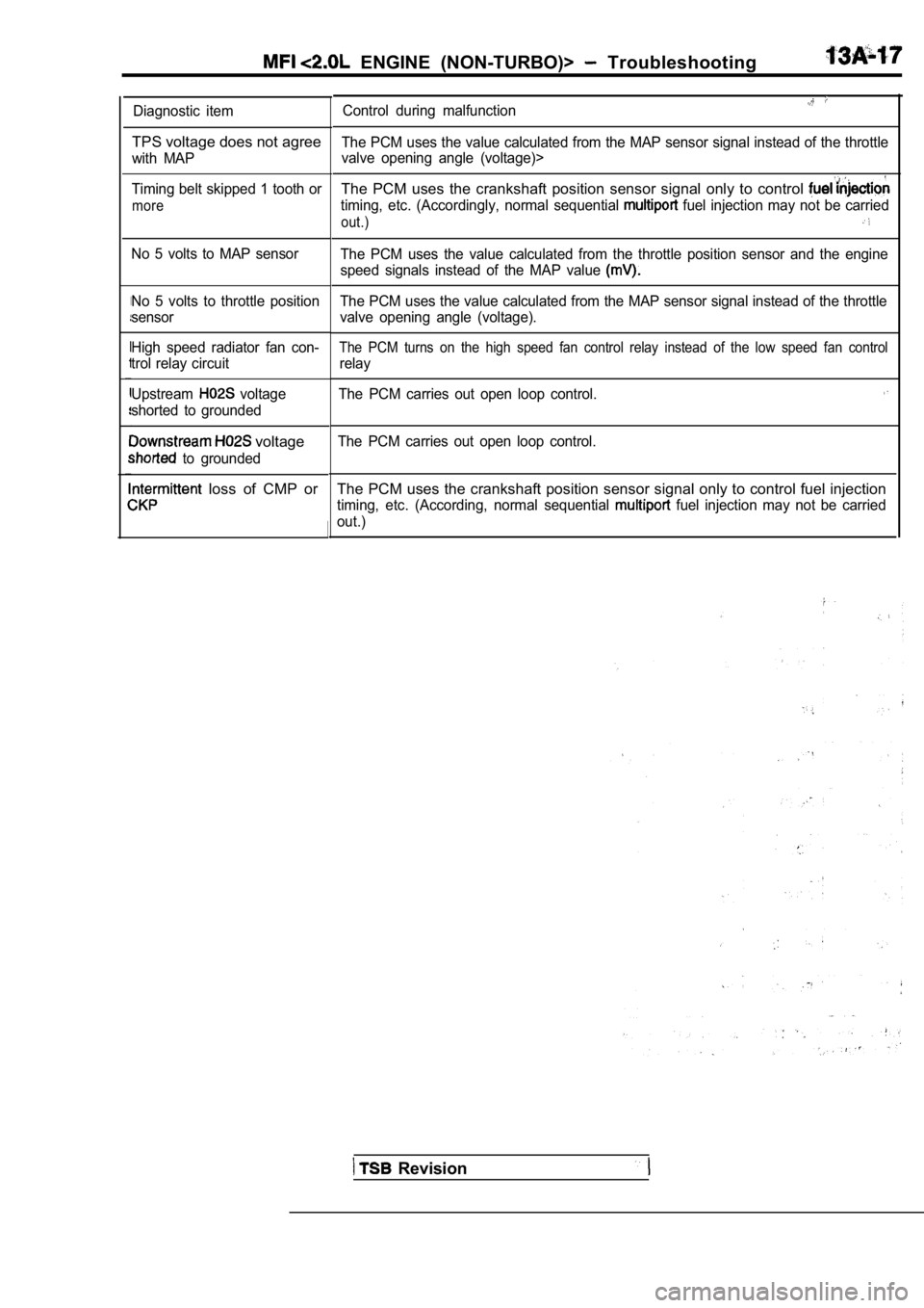
Diagnostic item
TPS voltage does not agree
with MAP
Timing belt skipped 1 tooth or
more
No 5 volts to MAP sensor
No 5 volts to throttle position
sensor
High speed radiator fan con-
trol relay circuit
Upstream
voltage
shorted to grounded
voltage
to grounded
loss of CMP or
Control during malfunction
The PCM uses the value calculated from the MAP sens or signal instead of the throttle
valve opening angle (voltage)>
The PCM uses the crankshaft position sensor signal only to control
timing, etc. (Accordingly, normal sequential fuel injection may not be carried
out.)
The PCM uses the value calculated from the throttle position sensor and the engine
speed signals instead of the MAP value
The PCM uses the value calculated from the MAP sens or signal instead of the throttle
valve opening angle (voltage).
The PCM turns on the high speed fan control relay i nstead of the low speed fan control
relay
The PCM carries out open loop control.
The PCM carries out open loop control.
The PCM uses the crankshaft position sensor signal only to control fuel injection
timing, etc. (According, normal sequential fuel injection may not be carried
out.)
Revision
Page 398 of 2103
ENGINE (NON-TURBO)> Troubleshooting
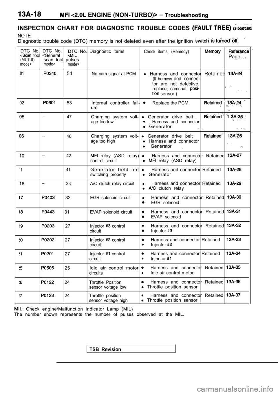
INSPECTION CHART FOR DIAGNOSTIC TROUBLE CODES
NOTE
Diagnostic trouble code (DTC) memory is not deleted even after the ignition
DTC No. DTC No.
DTC No. Diagnostic itemsCheck items, (Remedy) tool
mode>
mode>
01 54No cam signal at PCMl Harness and connector Retained
(If harness and connec-
tor are not defective,
replace; camshaft ,
sensor.) ,
02 53
Internal controller fail- Replace the PCM.,
. .
0547
46
Charging system volt- l Generator drive belt
age too lowlHarness and connector
l Generator. . ,
Charging system volt- l Generator drive belt
age too highl Harness and connector
l Generator
1042
1 141
1633
relay (ASD relay) lHarness and connector Retained
control circuitl relay (ASD relay)
G e n e r a t o r f i e l d n o t lHarness and connector Retained
switching properlyl Generator
A/C clutch relay circuitlHarness and connector Retained
l clutch relay
32
31
27
27
27
25
24
24
EGR solenoid circuitlHarness and connector Retained
EGR solenoid
EVAP solenoid circuit
Harness and connector Retained
EVAP solenoid
Injector
controllHarness and connector Retained
circuitInjector
Injector controlHarness and connector Retained
circuitlInjector
Injector controlHarness and connector Retained
circuitlInjector
Idle air control motor Harness and connector Retained
circuitslIdle air control motor
Throttle PositionHarness and connector Retained
sensor voltage lowl Throttle position sensor
Throttle positionlHarness and connector Retained
sensor voltage highl Throttle position sensor
TSB Revision
Check engine/Malfunction Indicator Lamp (MIL)
The number shown represents the number of pulses ob served at the MIL.
Page 399 of 2103
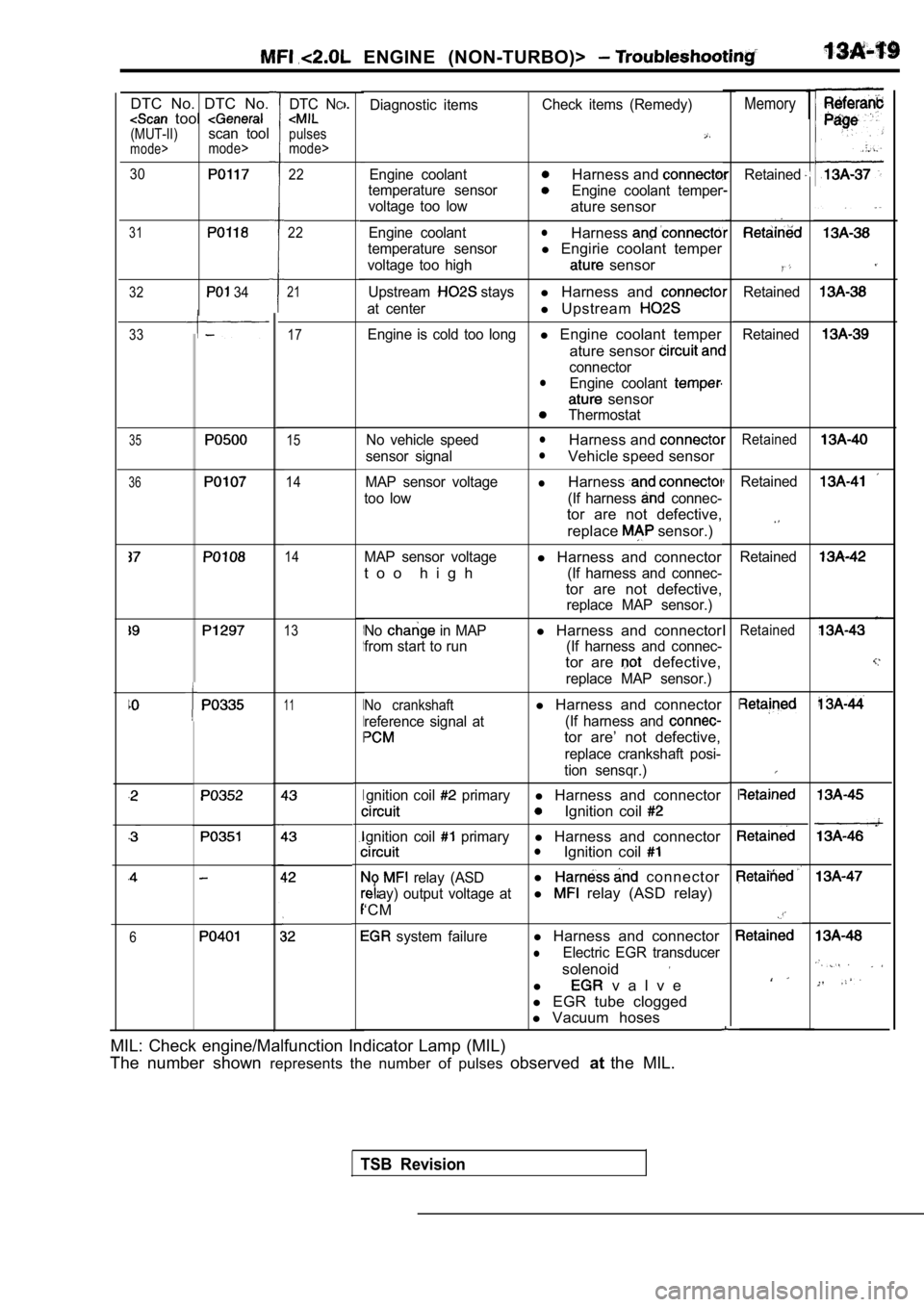
ENGINE (NON-TURBO)>
1MemoryDiagnostic itemsCheck items (Remedy)
Engine coolantHarness and
temperature sensorEngine coolant temper
voltage too low
ature sensor
Engine coolantlHarness
temperature sensorl Engirie coolant temper
voltage too high sensor
Upstream staysl Harness and
at centerl Upstream
Engine is cold too longl Engine coolant temper
ature sensor
connectorlEngine coolant
sensor
Thermostat
No vehicle speed
lHarness and
sensor signallVehicle speed sensor
MAP sensor voltagelHarness
too low (If harness connec-
tor are not defective, replace
sensor.)
MAP sensor voltagel Harness and connector
t o o h i g h
(If harness and connec-
tor are not defective,
replace MAP sensor.)
No
in MAPl Harness and connector
from start to run (If harness and connec-
tor are defective,
replace MAP sensor.)
No crankshaftl Harness and connector
reference signal at (If harness and
tor are’ not defective,
replace crankshaft posi-
tion sensqr.)
gnition coil
primaryl Harness and connector
Ignition coil
gnition coil primaryl Harness and connectorlIgnition coil
relay (ASDl connector
ay) output voltage atl relay (ASD relay)
‘CM
system failurel Harness and connector
lElectric EGR transducer
solenoid
l v a l v e
l EGR tube clogged
l Vacuum hoses
DTC NC
pulses
mode>
DTC No. DTC No. tool (MUT-II)scan toolmode>mode>
30
31
32 34
1
I
I
I
I
Retained22
22
,
I
I
I
Retained
Retained
21
17
15
14
14
33
35Retained
36Retained
Retained
13Retained
11
6
MIL: Check engine/Malfunction Indicator Lamp (MIL)
The number shown represents the number of pulses observedatthe MIL.
TSB Revision
Page 400 of 2103
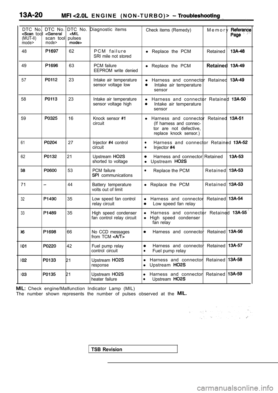
E N G I N E ( N O N - T U R B O ) >
DTC No. DTC No. DTC No. Diagnostic items tool (MUT-II)scan tool pulsesmode>mode>
48 62 P C M f a i l u r e
SRI mile not storedCheck items (Remedy)
l
Replace the PCM M e m o r yRetained
49 63PCM failurel
Replace the PCM Retained
EEPROM write denied
57 23Intake air temperaturel Harness and connector Retained
sensor voltage lowIntake air temperature
sensor
58
23Intake air temperaturel H a r n e s s a n d c o n n e c t o r R e t a i n e d
sensor voltage highIntake air temperature
sensor
59
16Knock sensor
circuit
l Harness and connector Retained
(If harness and connec-
tor are not defective,
replace knock sensor.)
61 27
62 21
53
Injector control
circuit
Upstream
shorted to voltage
PCM failure
communications
lH a r n e s s a n d c o n n e c t o r R e t a i n e d lInjector
Harness and connector Retained
l Upstream
lReplace the PCM R e t a i n e d
7144Battery temperature
volts out of limitl Replace the PCM R e t a i n e d
32 35
33 35
Low speed fan controll
Harness and connector Retained
relay circuitLow speed fan relay
High speed condenserl H a r n e s s a n d c o n n e c t o r R e t a i n e d
fan control relay circuitl High speed condenser
fan relay
66No CCD messages
from TCM Harness and connector Retained
42
21
21
Fuel pump relay
control circuit
Upstream
response
Upstream
heater failure
Harness and connector Retained
lFuel pump relay
l Harness and connector Retained
l Upstream
l Harness and connector Retained lUpstream
Check engine/Malfunction Indicator Lamp (MIL)
The number shown represents the number of pulses ob served at the
TSB Revision