MITSUBISHI SPYDER 1990 Service Repair Manual
Manufacturer: MITSUBISHI, Model Year: 1990, Model line: SPYDER, Model: MITSUBISHI SPYDER 1990Pages: 2103, PDF Size: 68.98 MB
Page 851 of 2103
CLUTCH OVERHAUL Clutch
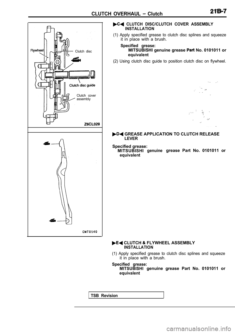
Clutch discClutch cover
assembly
CLUTCH DISC/CLUTCH COVER ASSEMBLY
INSTALLATION
(1) Apply specified grease to clutch disc splines a nd squeeze
it in place with a brush.
Specified grease:
MITSUBISHI genuine grease No. 0101011 or
equivalent
(2) Using clutch disc guide to position clutch disc on flywheel.
GREASE APPLICATION TO CLUTCH RELEASE
LEVER
Specified grease:
MITSUBISHI
genuinegrease Part No. 0101011 or
equivalent
CLUTCH FLYWHEEL ASSEMBLY
INSTALLATION
(1) Apply specified grease to clutch disc splines a nd squeeze
it in place with a brush.
Specified grease:
MITSUBISHI
genuine grease Part No. 0101011 or
equivalent
TSB Revision
Page 852 of 2103
21CLUTCH OVERHAUL Clutch
INSPECTION21200110043
Engine (Turbo) and Engine>
CLUTCH COVER ASSEMBLY
lCheck the diaphragm spring end for wear and uneven
height.
limit. if wear is evident ‘or height difference exceeds
Limit:
mm in.)
lCheck the pressure plate surface for wear, cracks a nd
seizure.
lCheck the strap plate rivets for looseness and replace
the clutch cover assembly if loose.
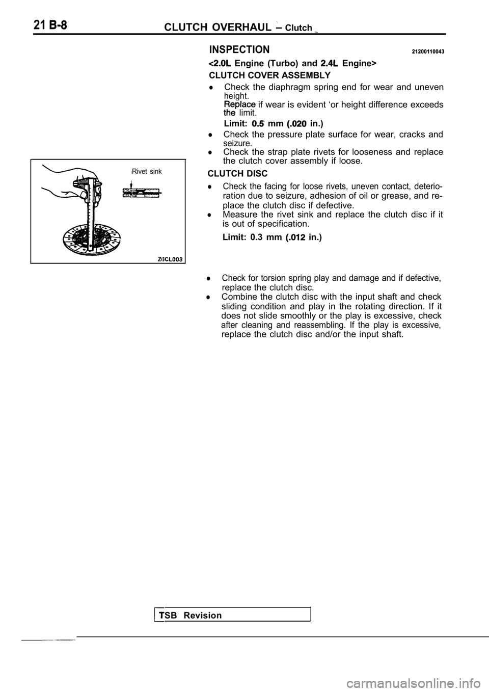
Rivet sink
TSB Revision
CLUTCH DISC
lCheck the facing for loose rivets, uneven contact, deterio-
ration due to seizure, adhesion of oil or grease, and re-
place the clutch disc if defective.
lMeasure the rivet sink and replace the clutch disc if it
is out of specification.
Limit: 0.3 mm
in.)
lCheck for torsion spring play and damage and if def ective,
replace the clutch disc.
lCombine the clutch disc with the input shaft and ch eck
sliding condition and play in the rotating directio n. If it
does not slide smoothly or the play is excessive, c heck
after cleaning and reassembling. If the play is exc essive,
replace the clutch disc and/or the input shaft.
Page 853 of 2103

CLUTCH OVERHAUL Clutch
CLUTCH RELEASE
Caution
Release bearing is packed with grease. do
wash it in cleaning solvent the like.
lCheck bearing for seizure, damage, noise, or improper
rotation. Check also diaphragm spring contact surfa ce
for wear.
lReplace bearing if its release fork contact surface is abnor-
mally worn.
RELEASE FORK
lReplace release fork if its bearing contact surface is abnor-
mally worn.
Engine (Non-turbo)>
CLUTCH
FLYWHEEL ASSEMBLY
l Check clutch assembly for contamination (dirt, oil) .
Replace clutch assembly, if required.
lCheck to see if the clutch disc hub are damaged.
Replace with new clutch assembly, if necessary.
lCheck for uneven wear on clutch fingers.
lCheck for broken clutch cover diaphragm spring fing ers.
Replace with new clutch assembly, if necessary.
CLUTCH RELEASE BEARING
lCheck to see if the release bearing is sticky or bi nding.
Replace bearing, if needed.
CLUTCH RELEASE LEVER/CLUTCH CONTROL EQUIP
STUD
lCheck linkage for excessive wear on the pivot stud and
fork fingers. Replace all worn parts.
TSB Revision
Page 854 of 2103
(Turbo)
CLUTCH RELEASE CYLINDER Engine (Turbo) and
Engine>
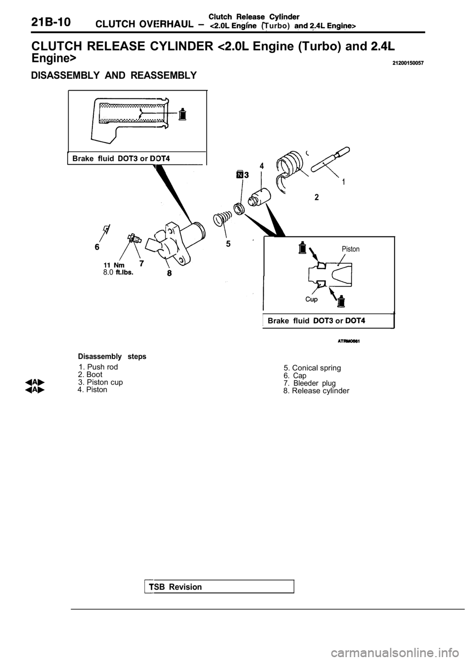
DISASSEMBLY AND REASSEMBLY
21200150057
Brake fluid or
8.0
TSB Revision
Disassembly steps
1. Push rod
2. Boot
3. Piston cup
4. Piston
4
q31
2
5Piston
IBrake fluid or
5. Conical spring6. Cap
7. Bleeder plug
8. Release cylinder
Page 855 of 2103
Clutch Release Cylinder
CLUTCH
Engine (Turbo) and Engine>
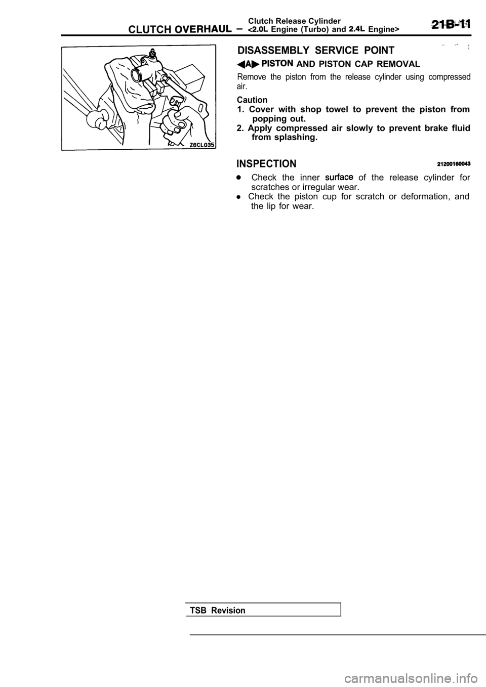
DISASSEMBLY SERVICE POINT
AND PISTON CAP REMOVAL
Remove the piston from the release cylinder using c ompressed
air.
Caution
1. Cover with shop towel to prevent the piston from
popping out.
2. Apply compressed air slowly to prevent brake flu id
from splashing.
INSPECTION
Check the inner of the release cylinder for
scratches or irregular wear.
l Check the piston cup for scratch or deformation, an d
the lip for wear.
TSB Revision
Page 856 of 2103
NOTES
Page 857 of 2103
CONTENTS
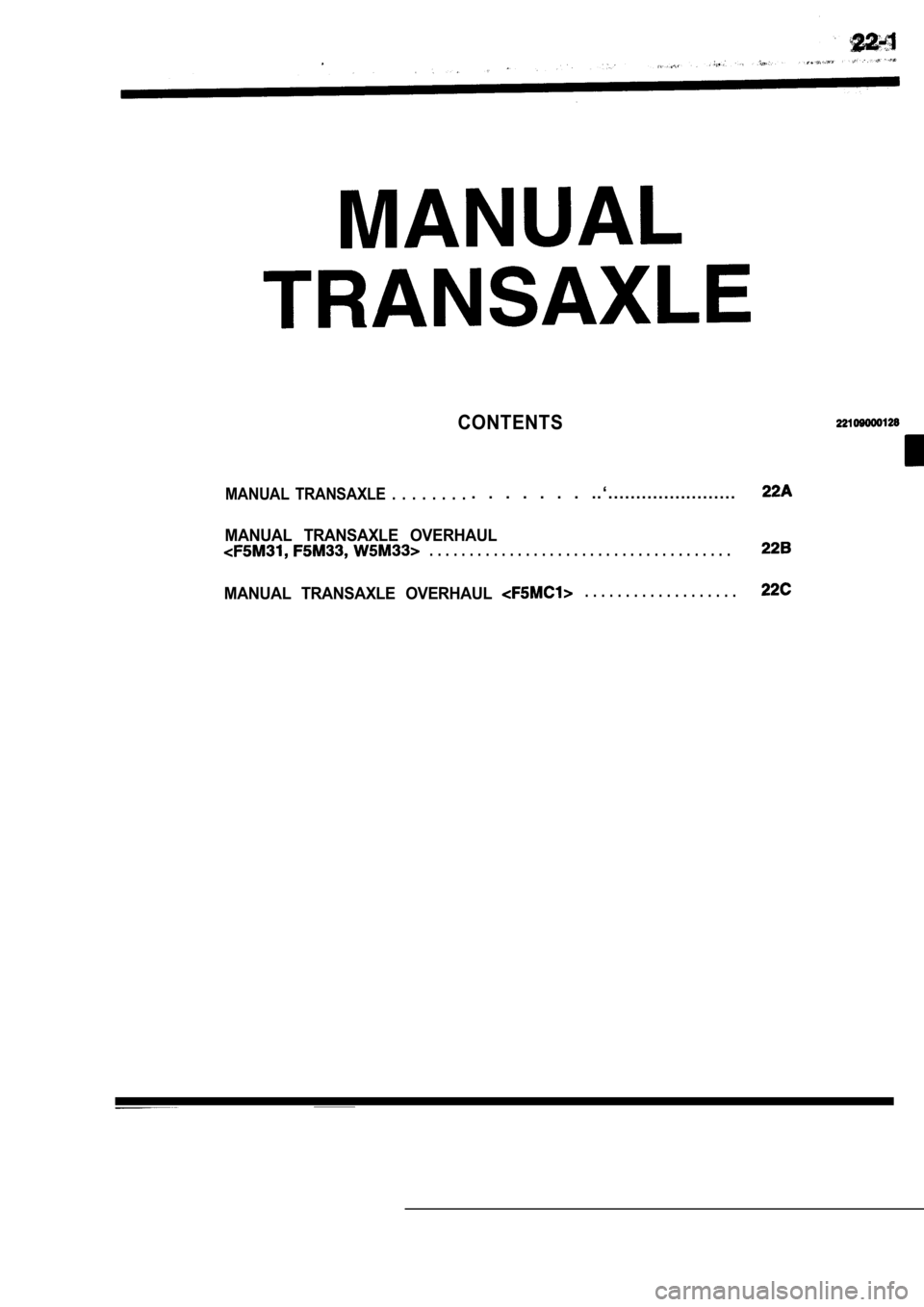
MANUAL TRANSAXLE . . . . . . . .. . . . . . . . . ‘ . . . . . . . . . . . . . . . . . . . . . . .
MANUAL TRANSAXLE OVERHAUL. . . . . . . . . . . . . . . . . . . . . . . . . . . . . . . . . . . . . .
MANUAL TRANSAXLE OVERHAUL . . . . . . . . . . . . . . . . . . .
Page 858 of 2103

NOTES
Page 859 of 2103
CONTENTS
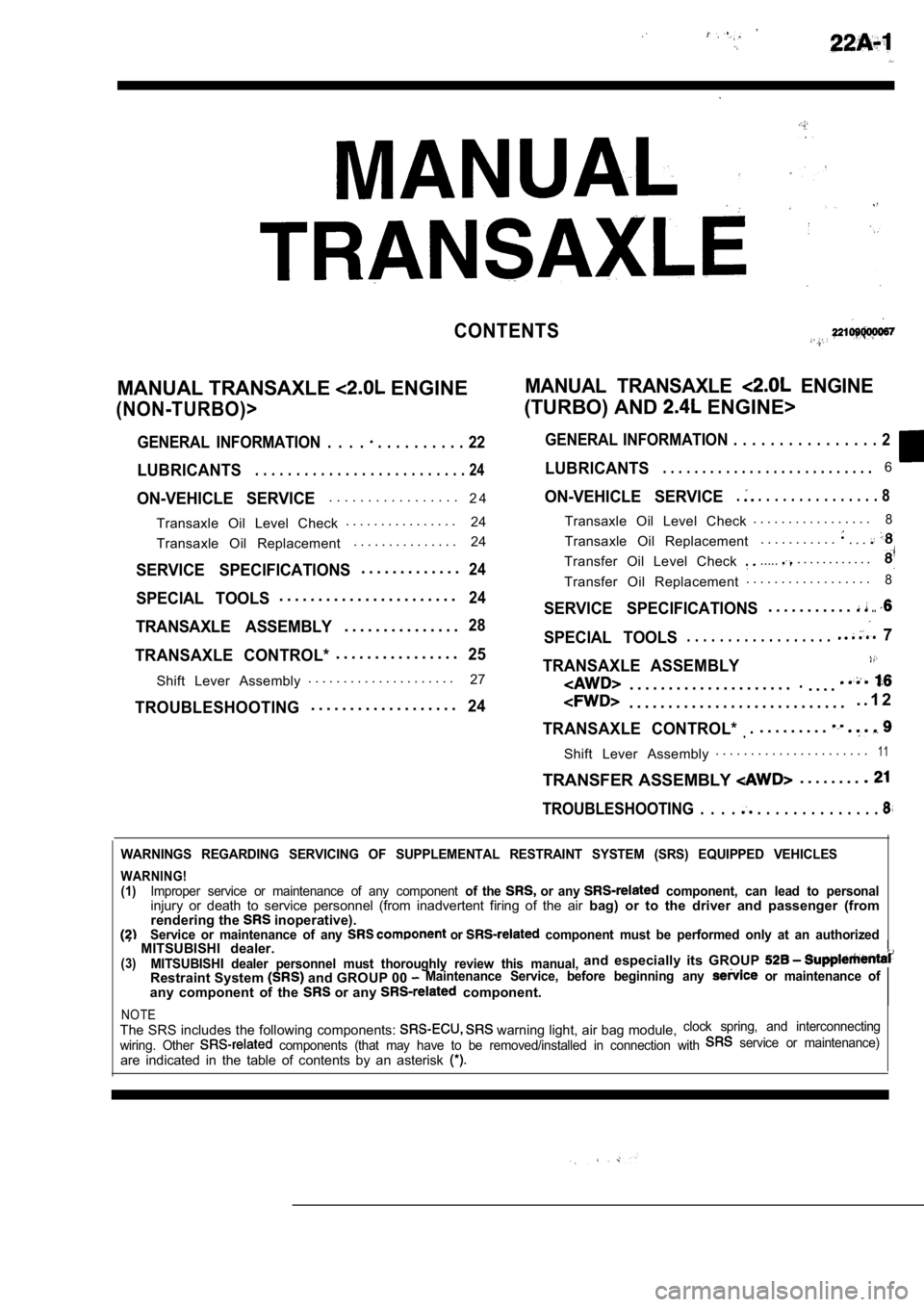
MANUAL TRANSAXLE ENGINEMANUAL TRANSAXLE ENGINE
(NON-TURBO)>(TURBO) AND ENGINE>
GENERAL INFORMATION . . . . . . . . . . . . . . 22GENERAL INFORMATION . . . . . . . . . . . . . . . .
2
LUBRICANTS. . . . . . . . . . . . . . . . . . . . . . . . . . 24LUBRICANTS. . . . . . . . . . . . . . . . . . . . . . . . . . .6
ON-VEHICLE SERVICE. . . . . . . . . . . . . . . . .
2 4
Transaxle Oil Level Check . . . . . . . . . . . . . . . .
24
Transaxle Oil Replacement . . . . . . . . . . . . . . .
24
SERVICE SPECIFICATIONS. . . . . . . . . . . . .24
SPECIAL TOOLS. . . . . . . . . . . . . . . . . . . . . . .24
TRANSAXLE ASSEMBLY. . . . . . . . . . . . . . .28
TRANSAXLE CONTROL*. . . . . . . . . . . . . . . .25ON-VEHICLE SERVICE
. . . . . . . . . . . . . . . . 8
Shift Lever Assembly
. . . . . . . . . . . . . . . . . . . . .
27
TROUBLESHOOTING. . . . . . . . . . . . . . . . . . .24
Transaxle Oil Level Check . . . . . . . . . . . . . . . . .8
Transaxle Oil Replacement
. . . . . . . . . . .. . .
Transfer Oil Level Check ...... . . . . . . . . . . .
Transfer Oil Replacement. . . . . . . . . . . . . . . . . .8
SERVICE SPECIFICATIONS. . . . . . . . . . ...
SPECIAL TOOLS 7. . . . . . . . . . . . . . . . . .
TRANSAXLE ASSEMBLY
. . . . . . . . . . . . . . . . . . . . ... . . .
. . . . . . . . . . . . . . . . . . . . . . . . . . . .
. . 1 2
TRANSAXLE CONTROL*... . . . . . . . .
Shift Lever Assembly. . . . . . . . . . . . . . . . . . . . . .1 1
TRANSFER ASSEMBLY . . . . . . . .
TROUBLESHOOTING . . . . . . . . . . . . . . . . . .
WARNINGS REGARDING SERVICING OF SUPPLEMENTAL RESTRA
INT SYSTEM (SRS) EQUIPPED VEHICLES
WARNING!
(1)Improper service or maintenance of any component of the or any component, can lead to personalinjury or death to service personnel (from inadvertent firing of the air bag) or to the driver and passenger (from
rendering the inoperative).Service or maintenance of any or component must be performed only at an authorized MITSUBISHI dealer.(3)MITSUBISHI dealer personnel must thoroughly review this manual,and especially its GROUP
Restraint System and GROUP 00 Maintenance Service, before beginning any or maintenance of
any component of the or any component.
NOTEThe SRS includes the following components: warning light, air bag module,clock spring, and interconnecting
wiring. Other
components (that may have to be removed/installed in connection with service or maintenance)
are indicated in the table of contents by an asterisk
Page 860 of 2103
MANUAL TRANSAXLE
ENGINE (TURBO) AND General Information
GENERAL
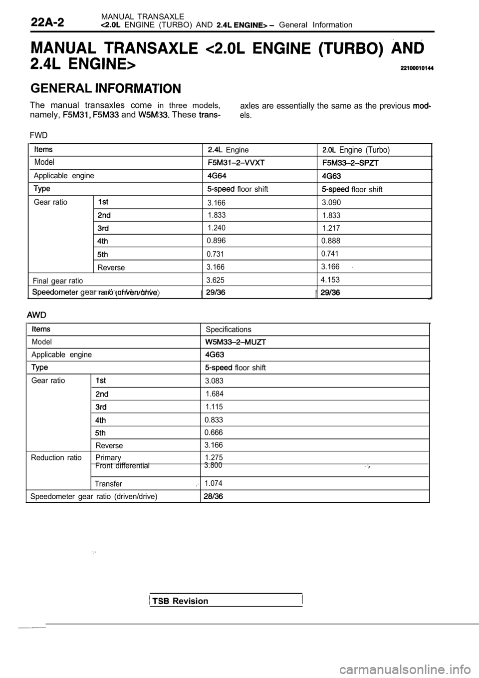
The manual transaxles come in three models,
namely,
and These
axles are essentially the same as the previous
els.
FWD
Engine
Model
Applicable engine
floor shift
Gear ratio
3.166
1.833
1.240
0.896
0.731
Reverse3.166
Final
gearratio 3.625
gear
Engine (Turbo)
floor shift
3.090
1.833
1.217
0.888
0.741
3.166
4.153
Specifications
Model
Applicable engine
floor shift
Gear ratio
3.083
1.684
1.115
0.833
0.666
Reverse 3.166
Reduction ratio Primary
1.275
Front differential3.800
Transfer1.074
Speedometer gear ratio (driven/drive)
Revision