MITSUBISHI SPYDER 1990 Service Repair Manual
Manufacturer: MITSUBISHI, Model Year: 1990, Model line: SPYDER, Model: MITSUBISHI SPYDER 1990Pages: 2103, PDF Size: 68.98 MB
Page 871 of 2103
MANUAL TRANSAXLE
-ENGINE (TURBO) AND ENGINE> Transaxle
Engine>
13
27
Engine>2 2 - 2 52 61813
I
78
85
20
Nm51-58
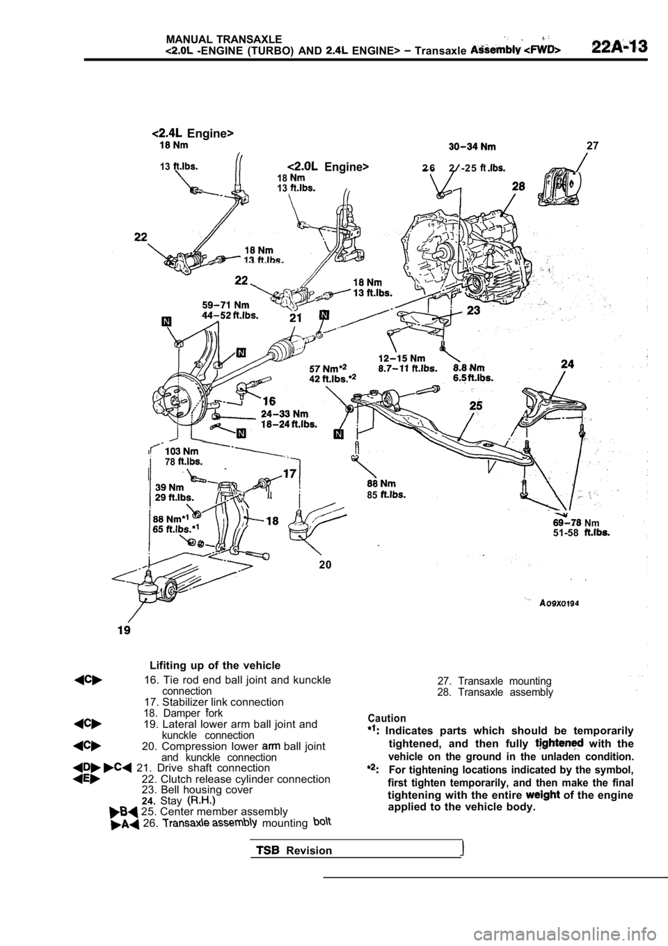
Lifiting up of the vehicle
16. Tie rod end ball joint and kunckleconnection17. Stabilizer link connection18. Damper fork19. Lateral lower arm ball joint andkunckle connection20. Compression lower ball jointand kunckle connection 21. Drive shaft connection
22. Clutch release cylinder connection
23. Bell housing cover
24.Stay
27. Transaxle mounting
28. Transaxle assembly
25. Center member assembly
26. mounting
Caution
Indicates parts which should be temporarily
tightened, and then fully
with the
vehicle on the ground in the unladen condition.
For tightening locations indicated by the symbol,
first tighten temporarily, and then make the final
tightening with the entire of the engine
applied to the vehicle body.
Revision
Page 872 of 2103
MANUAL TRANSAXLE
ENGINE AND ENGINE> Transaxle Assembly
I
Nut
ITransaxle
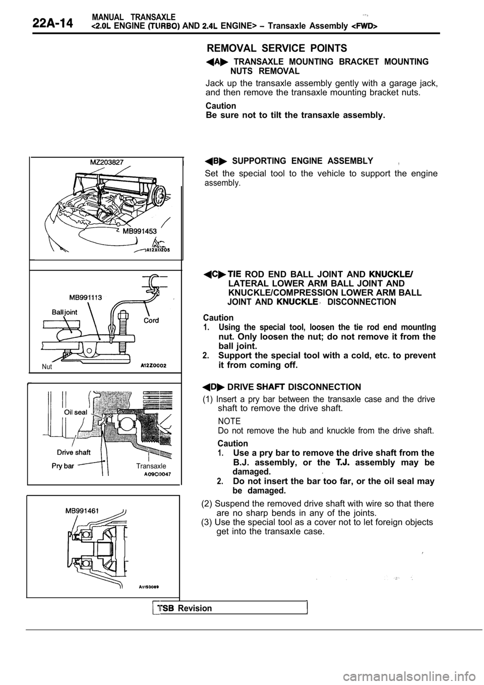
REMOVAL SERVICE POINTS
TRANSAXLE MOUNTING BRACKET MOUNTINGNUTS REMOVAL
Jack up the transaxle assembly gently with a garage jack,
and then remove the transaxle mounting bracket nuts .
Caution
Be sure not to tilt the transaxle assembly.
SUPPORTING ENGINE ASSEMBLY,
Set the special tool to the vehicle to support the engine
assembly.
ROD END BALL JOINT AND
LATERAL LOWER ARM BALL JOINT AND
KNUCKLE/COMPRESSION LOWER ARM BALL
JOINT AND DISCONNECTION
Caution
1.Using the special tool, loosen the tie rod end moun tlng
nut. Only loosen the nut; do not remove it from the
ball joint.
2.Support the special tool with a cold, etc. to prevent
it from coming off.
DRIVE DISCONNECTION
(1) Insert a pry bar between the transaxle case and the drive
shaft to remove the drive shaft.
NOTE
Do not remove the hub and knuckle from the drive sh aft.
Caution
1.Use a pry bar to remove the drive shaft from the
B.J. assembly, or the
assembly may be
damaged.
2.Do not insert the bar too far, or the oil seal may
be damaged.
(2) Suspend the removed drive shaft with wire so that there
are no sharp bends in any of the joints.
(3) Use the special tool as a cover not to let fore ign objects
get into the transaxle case.
Revision
Page 873 of 2103
MANUAL TRANSAXLE
ENGINE (TURBO) AND ENGINE> Transaxle Assembly
TransaxlemountTransaxle side
stopper
Front roll
member
CLUTCH.
Remove the clutch release cylinder without disconne cting
the oil line, and suspend
a nearby “a
etc.
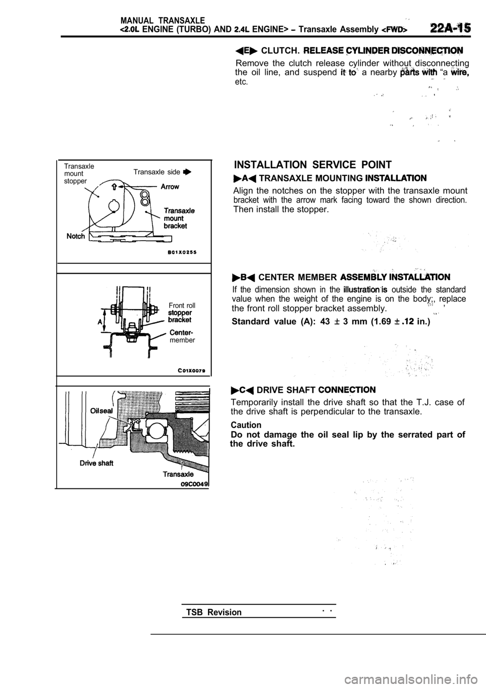
INSTALLATION SERVICE POINT
TRANSAXLE MOUNTING
Align the notches on the stopper with the transaxle mount
bracket with the arrow mark facing toward the shown direction.
Then install the stopper.
CENTER MEMBER
If the dimension shown in the outside the standard
value when the weight of the engine is on the body;, replace
the front roll stopper bracket assembly. ,
Standard value (A): 43
3 mm (1.69 in.)
DRIVE SHAFT
Temporarily install the drive shaft so that the T.J . case of
the drive shaft is perpendicular to the transaxle.
Caution
Do not damage the oil seal lip by the serrated part of
the drive shaft.
TSB Revision. .
Page 874 of 2103
MANUAL ,
ENGINE AND Transaxle Assembly .
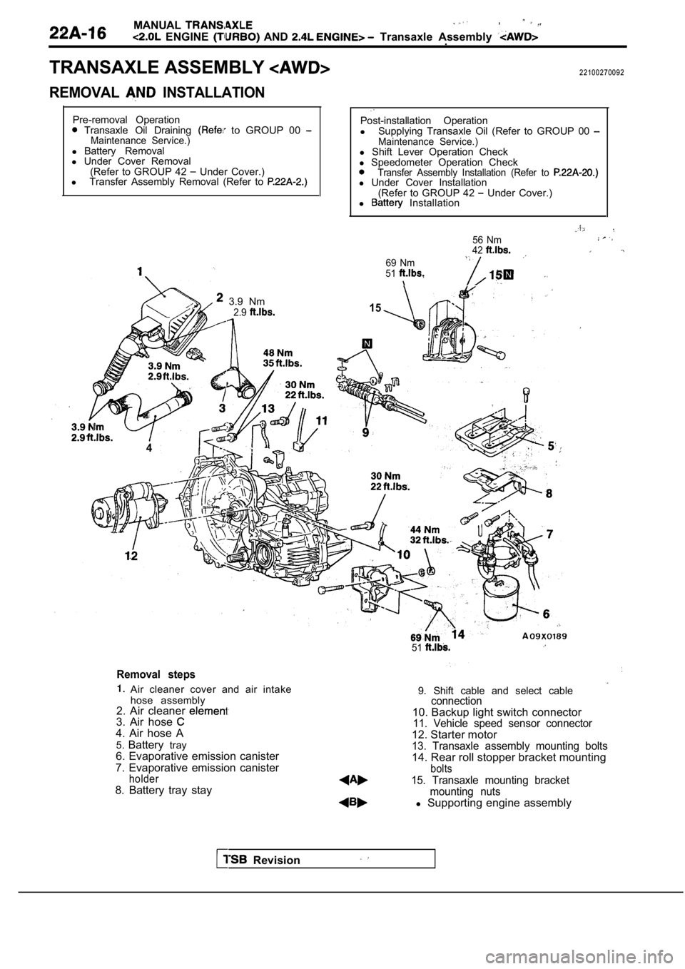
TRANSAXLE ASSEMBLY
REMOVAL INSTALLATION
22100270092
Pre-removal Operation
Transaxle Oil Draining to GROUP 00 Maintenance Service.)l Battery Removal
l Under Cover Removal
(Refer to GROUP 42
Under Cover.)
l Transfer Assembly Removal (Refer to
3.9 Nm
4
2.9
Post-installation Operation
l Supplying Transaxle Oil (Refer to GROUP 00
Maintenance Service.)l Shift Lever Operation Check
l Speedometer Operation Check
Transfer Assembly Installation (Refer to l Under Cover Installation
(Refer to GROUP 42 Under Cover.)
l Installation
69 Nm
51
56 Nm
42
15
51
Removal steps
Air cleaner cover and air intake
hose assembly
2. Air cleaner
3. Air hose 4. Air hose A
5. Battery tray
6. Evaporative emission canister
7. Evaporative emission canister
holder8. Battery tray stay 9. Shift cable and select cable
connection10. Backup light switch connector11. Vehicle speed sensor connector12. Starter motor13. Transaxle assembly mounting bolts14. Rear roll stopper bracket mountingbolts
15. Transaxle mounting bracket
mounting nuts
l Supporting engine assembly
Revision
Page 875 of 2103
MANUAL TRANSAXLE
ENGINE (TURBO) AND ENGINE> Transaxle Assembly
34 Nm
2 4 ’ . .
59-71 Nm
44-528.8 Nm8.5
26
7 8
85
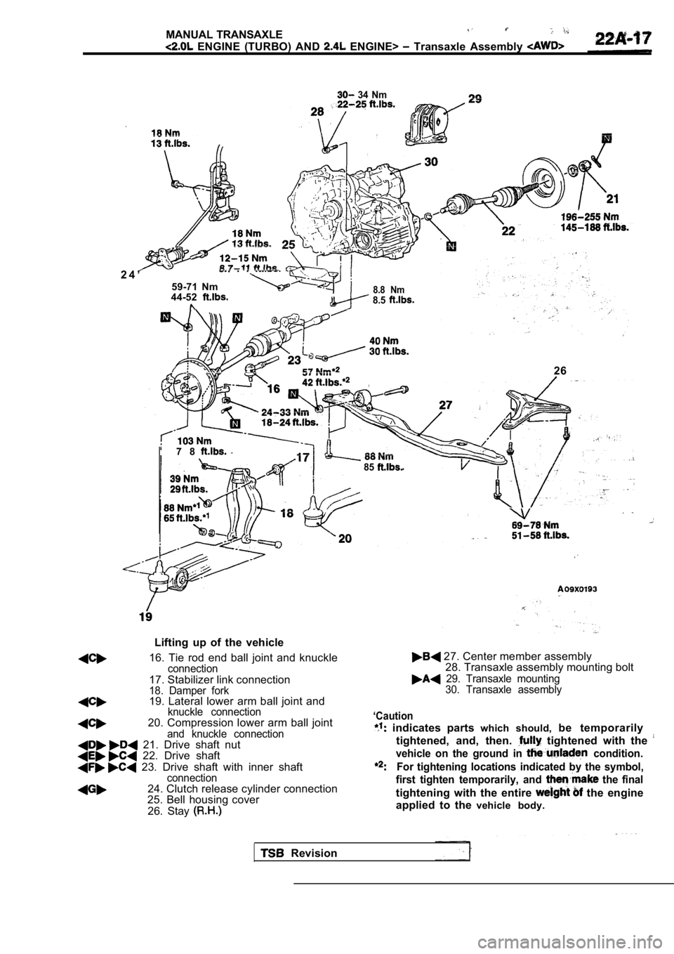
Lifting up of the vehicle
16. Tie rod end ball joint and knuckle
connection17. Stabilizer link connection18. Damper fork19. Lateral lower arm ball joint and
27. Center member assembly 28. Transaxle assembly mounting bolt
29. Transaxle mounting 30. Transaxle assembly
knuckle connection
20. Compression lower arm ball jointand knuckle connection 21. Drive shaft nut 22. Drive shaft
23. Drive shaft with inner shaftconnection24. Clutch release cylinder connection
25. Bell housing cover
26. Stay
‘Caution
indicates parts which should, be temporarily
tightened, and, then.
tightened with the
vehicle on the ground in condition.
For tightening locations indicated by the symbol,
first tighten temporarily, and
the final
tightening with the entire the engine
applied to the vehicle body.
Revision
Page 876 of 2103
MANUAL TRANSAXLE
ENGINE AND ENGINE> Transaxle Assembly
I -
Cord
I’ --
Nut
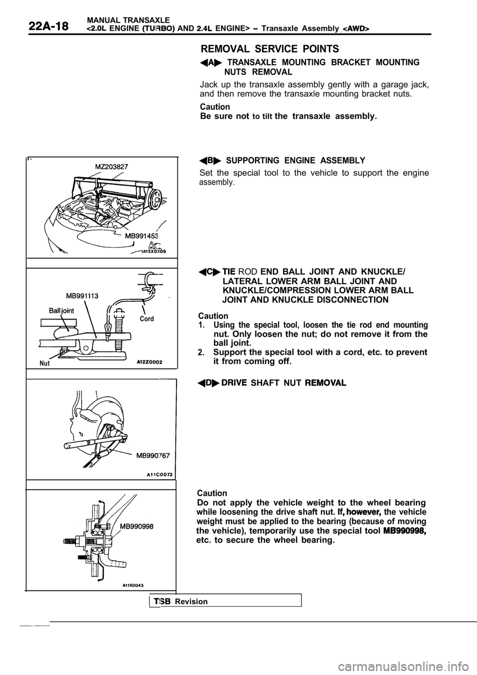
REMOVAL SERVICE POINTS
TRANSAXLE MOUNTING BRACKET MOUNTINGNUTS REMOVAL
Jack up the transaxle assembly gently with a garage jack,
and then remove the transaxle mounting bracket nuts .
Caution
Be sure not to tilt the transaxle assembly.
SUPPORTING ENGINE ASSEMBLY
Set the special tool to the vehicle to support the engine
assembly.
ROD END BALL JOINT AND KNUCKLE/
LATERAL LOWER ARM BALL JOINT AND
KNUCKLE/COMPRESSION LOWER ARM BALL
JOINT AND KNUCKLE DISCONNECTION
Caution
1.Using the special tool, loosen the tie rod end moun ting
nut. Only loosen the nut; do not remove it from the
ball joint.
2.Support the special tool with a cord, etc. to preve nt
it from coming off.
SHAFT NUT
Caution
Do not apply the vehicle weight to the wheel bearin g
while loosening the drive shaft nut. the vehicle
weight must be applied to the bearing (because of m oving
the vehicle), temporarily use the special tool
etc. to secure the wheel bearing.
I Revision
Page 877 of 2103
MANUAL TRANSAXLE
ENGINE (TURBO) AND ENGINE> Transaxle Assembly
11
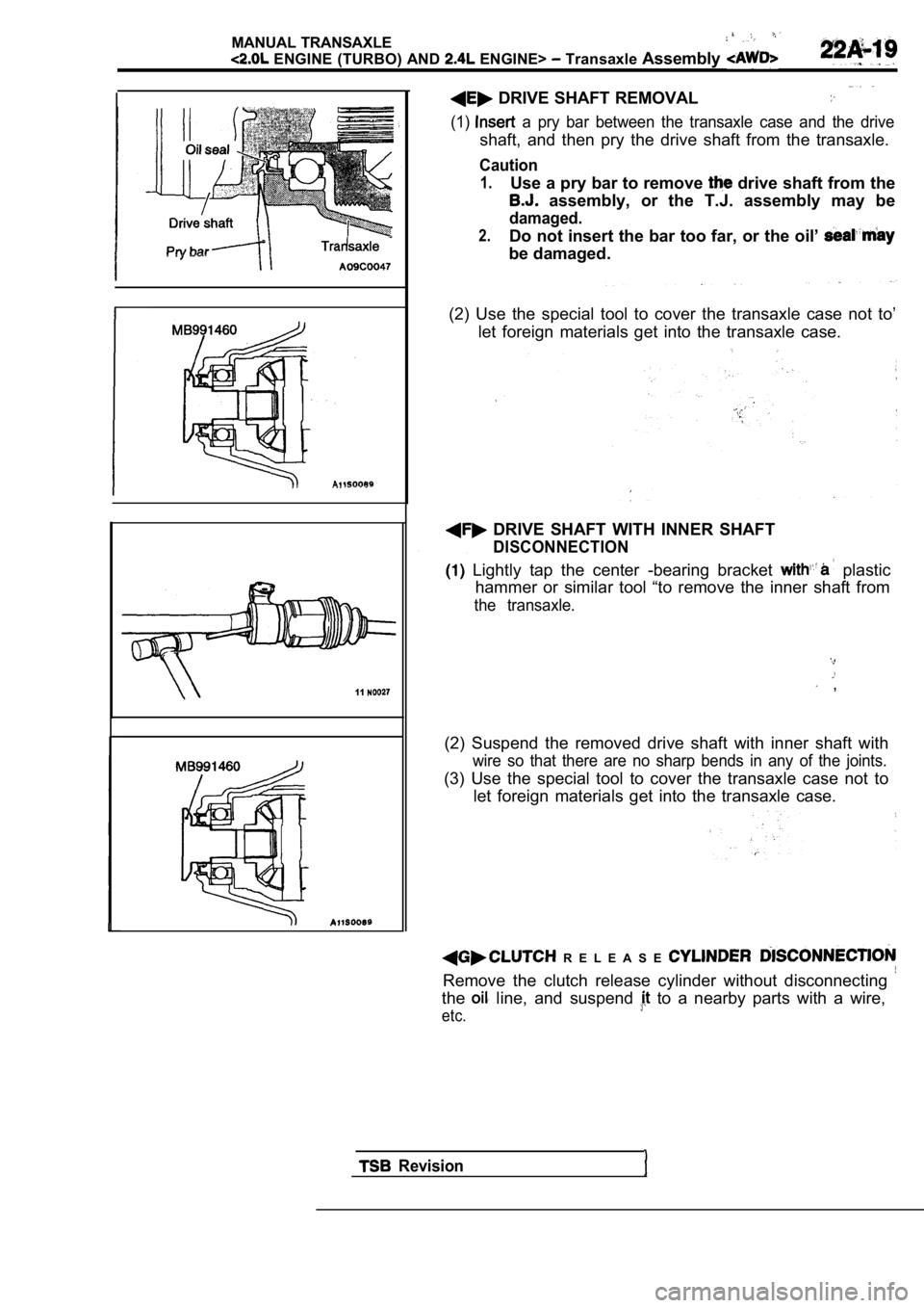
DRIVE SHAFT REMOVAL
(1) a pry bar between the transaxle case and the drive
shaft, and then pry the drive shaft from the transa xle.
Caution
1.Use a pry bar to remove drive shaft from the
assembly, or the T.J. assembly may be
damaged.
2.Do not insert the bar too far, or the oil’
be damaged.
(2) Use the special tool to cover the transaxle cas e not to’
let foreign materials get into the transaxle case.
DRIVE SHAFT WITH INNER SHAFT
DISCONNECTION
Lightly tap the center -bearing bracket plastic
hammer or similar tool “to remove the inner shaft f rom
the transaxle.
,
(2) Suspend the removed drive shaft with inner shaf t with
wire so that there are no sharp bends in any of the joints.
(3) Use the special tool to cover the transaxle case not to
let foreign materials get into the transaxle case.
R E L E A S E
Remove the clutch release cylinder without disconne cting
the line, and suspend to a nearby parts with a wire,
etc.
Revision
Page 878 of 2103
MANUAL TRANSAXLE
ENGINE (TURBO) AND ENGINE> Transaxle Assembly
TransaxlemountTransaxle side
s t o p p e r ,ArrowTransaxlemount
Frontstopperbracket
member
Revision
Washer
196-255 Nm
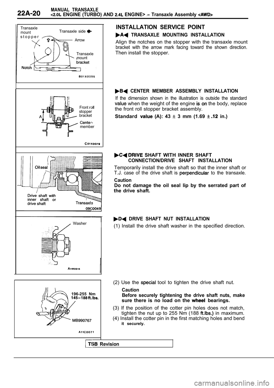
INSTALLATION SERVICE POINT
TRANSAXLE MOUNTING INSTALLATION
Align the notches on the stopper with the transaxle mount
bracket with the arrow mark facing toward the shown direction.
Then install the stopper.
CENTER MEMBER ASSEMBLY INSTALLATION
If the dimension shown in the illustration is outside the standard
when the weight of the engine the body, replace
the front roll stopper bracket assembly.
Standard
(A): 43 3 mm (1.69 in.)
SHAFT WITH INNER SHAFT
CONNECTION/DRIVE SHAFT INSTALLATION
Temporarily install the drive shaft so that the inn er shaft or
T.J. case of the drive shaft is to the transaxle.
Caution
Do not damage the oil seal lip by the serrated part of
the drive shaft.
DRIVE SHAFT NUT INSTALLATION
(1) Install the drive shaft washer in the specified direction.
(2) Use the
tool to tighten the drive shaft nut.
Caution Before securely tightening the drive shaft nuts, ma ke
sure there is no load on the bearings.
(3) If the position of the cotter pin holes does no t match,
tighten the nut up to 255 Nm (188
in maximum.
(4) Install the cotter pin in the first matching ho les and bend
it securely.
Page 879 of 2103
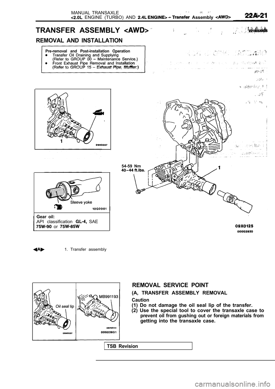
MANUAL TRANSAXLE ENGINE (TURBO) AND Assembly
TRANSFER ASSEMBLY
REMOVAL AND INSTALLATION
Pre-removal and Post-installation Operation
(Refer to GROUP 15 Exhaust Pipe, Muffler.)
Gear oil:
API classification SAE
or
1. Transfer assembly
54-59 Nm
REMOVAL SERVICE POINT
(A, TRANSFER ASSEMBLY REMOVAL
Caution
(1) Do not damage the oil seal lip of the transfer.
(2) Use the special tool to cover the transaxle cas e to
prevent oil from gushing out or foreign materials from
getting into the transaxle case.
TSB Revision
Page 880 of 2103
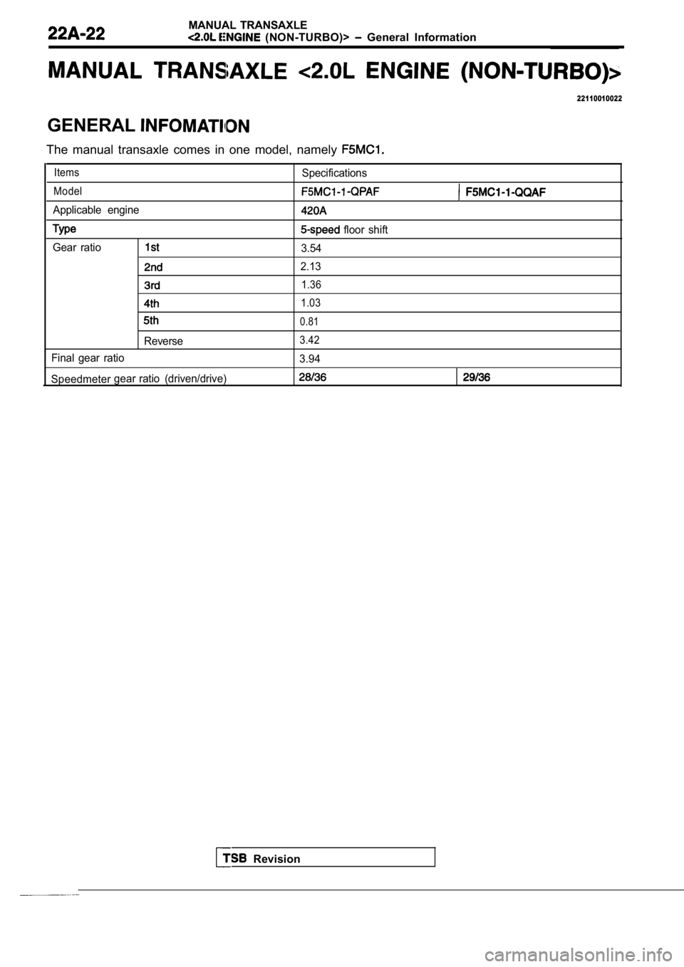
MANUAL TRANSAXLE
(NON-TURBO)> General Information
22110010022
GENERAL
The manual transaxle comes in one model, namely
ItemsSpecifications
Model
Applicable engine
floor shift
Gear ratio
3.54
2.13
1.36
1.03
0.81
Reverse3.42
Final gear ratio 3.94
Speedmeter gear ratio (driven/drive)
Revision