NISSAN ALMERA 2001 Service Manual
Manufacturer: NISSAN, Model Year: 2001, Model line: ALMERA, Model: NISSAN ALMERA 2001Pages: 2898, PDF Size: 60.76 MB
Page 2621 of 2898
NJMT0091
Differential Side Bearing PreloadNJMT0091S01If any of the following parts are replaced, adjust differential side
bearing preload.
+Differential case
+Differential side bearing
+Clutch housing
+Transmission case
SMT645-A
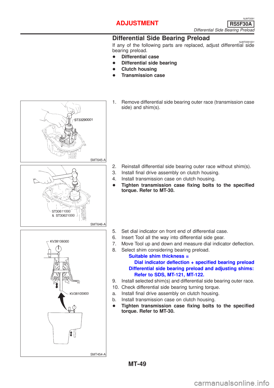
1. Remove differential side bearing outer race (transmission case
side) and shim(s).
SMT646-A
2. Reinstall differential side bearing outer race without shim(s).
3. Install final drive assembly on clutch housing.
4. Install transmission case on clutch housing.
+Tighten transmission case fixing bolts to the specified
torque. Refer to MT-30.
SMT454-A
5. Set dial indicator on front end of differential case.
6. Insert Tool all the way into differential side gear.
7. Move Tool up and down and measure dial indicator deflection.
8. Select shim considering bearing preload.
Suitable shim thickness =
Dial indicator deflection + specified bearing preload
Differential side bearing preload and adjusting shims:
Refer to SDS, MT-121, MT-122.
9. Install selected shim(s) and differential side bearing outer race.
10. Check differential side bearing turning torque.
a. Install final drive assembly on clutch housing.
b. Install transmission case on clutch housing.
+Tighten transmission case fixing bolts to the specified
torque. Refer to MT-30.
ADJUSTMENTRS5F30A
Differential Side Bearing Preload
MT-49
Page 2622 of 2898
SMT600-A
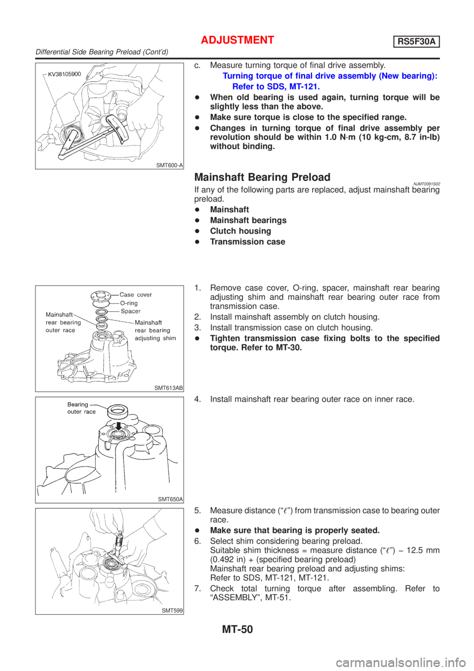
c. Measure turning torque of final drive assembly.
Turning torque of final drive assembly (New bearing):
Refer to SDS, MT-121.
+When old bearing is used again, turning torque will be
slightly less than the above.
+Make sure torque is close to the specified range.
+Changes in turning torque of final drive assembly per
revolution should be within 1.0 N´m (10 kg-cm, 8.7 in-lb)
without binding.
Mainshaft Bearing PreloadNJMT0091S02If any of the following parts are replaced, adjust mainshaft bearing
preload.
+Mainshaft
+Mainshaft bearings
+Clutch housing
+Transmission case
SMT613AB
1. Remove case cover, O-ring, spacer, mainshaft rear bearing
adjusting shim and mainshaft rear bearing outer race from
transmission case.
2. Install mainshaft assembly on clutch housing.
3. Install transmission case on clutch housing.
+Tighten transmission case fixing bolts to the specified
torque. Refer to MT-30.
SMT650A
4. Install mainshaft rear bearing outer race on inner race.
SMT599
5. Measure distance (ª!º) from transmission case to bearing outer
race.
+Make sure that bearing is properly seated.
6. Select shim considering bearing preload.
Suitable shim thickness = measure distance (ª!º) þ 12.5 mm
(0.492 in) + (specified bearing preload)
Mainshaft rear bearing preload and adjusting shims:
Refer to SDS, MT-121, MT-121.
7. Check total turning torque after assembling. Refer to
ªASSEMBLYº, MT-51.
ADJUSTMENTRS5F30A
Differential Side Bearing Preload (Cont'd)
MT-50
Page 2623 of 2898
NJMT0092
SMT586
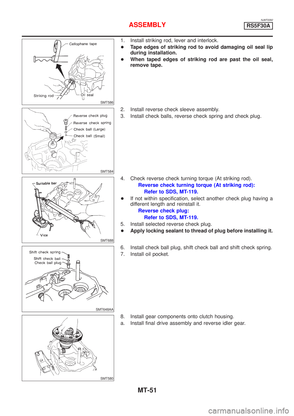
1. Install striking rod, lever and interlock.
+Tape edges of striking rod to avoid damaging oil seal lip
during installation.
+When taped edges of striking rod are past the oil seal,
remove tape.
SMT584
2. Install reverse check sleeve assembly.
3. Install check balls, reverse check spring and check plug.
SMT688
4. Check reverse check turning torque (At striking rod).
Reverse check turning torque (At striking rod):
Refer to SDS, MT-119.
+If not within specification, select another check plug having a
different length and reinstall it.
Reverse check plug:
Refer to SDS, MT-119.
5. Install selected reverse check plug.
+Apply locking sealant to thread of plug before installing it.
SMT648AA
6. Install check ball plug, shift check ball and shift check spring.
7. Install oil pocket.
SMT580
8. Install gear components onto clutch housing.
a. Install final drive assembly and reverse idler gear.
ASSEMBLYRS5F30A
MT-51
Page 2624 of 2898
SMT737A
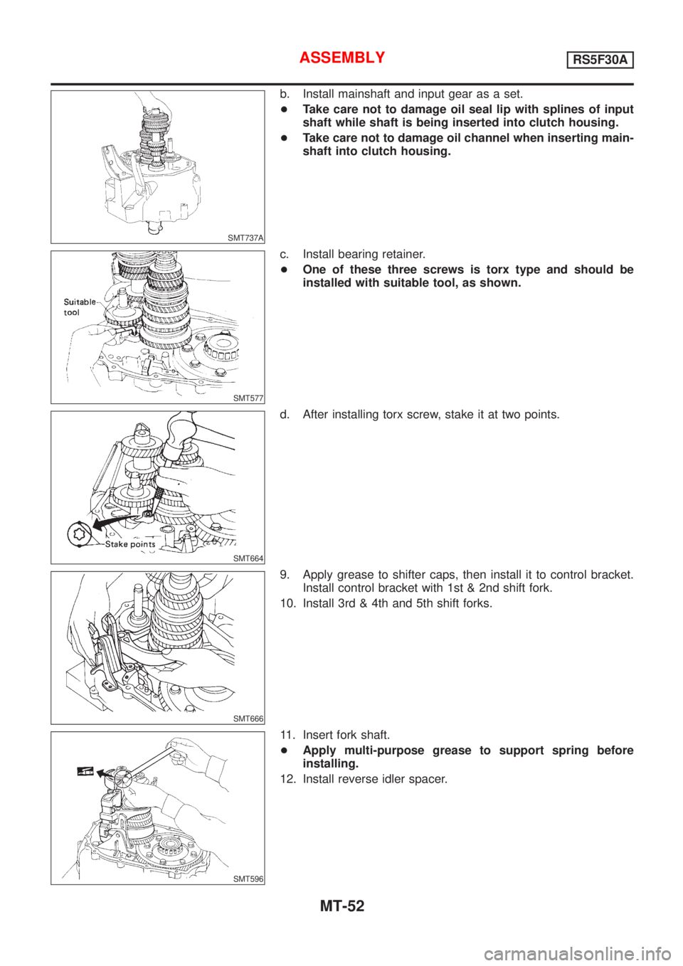
b. Install mainshaft and input gear as a set.
+Take care not to damage oil seal lip with splines of input
shaft while shaft is being inserted into clutch housing.
+Take care not to damage oil channel when inserting main-
shaft into clutch housing.
SMT577
c. Install bearing retainer.
+One of these three screws is torx type and should be
installed with suitable tool, as shown.
SMT664
d. After installing torx screw, stake it at two points.
SMT666
9. Apply grease to shifter caps, then install it to control bracket.
Install control bracket with 1st & 2nd shift fork.
10. Install 3rd & 4th and 5th shift forks.
SMT596
11. Insert fork shaft.
+Apply multi-purpose grease to support spring before
installing.
12. Install reverse idler spacer.
ASSEMBLYRS5F30A
MT-52
Page 2625 of 2898
SMT587
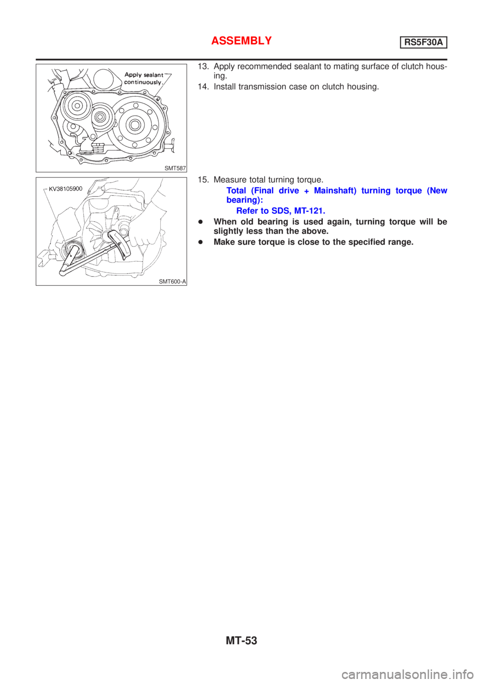
13. Apply recommended sealant to mating surface of clutch hous-
ing.
14. Install transmission case on clutch housing.
SMT600-A
15. Measure total turning torque.
Total (Final drive + Mainshaft) turning torque (New
bearing):
Refer to SDS, MT-121.
+When old bearing is used again, turning torque will be
slightly less than the above.
+Make sure torque is close to the specified range.
ASSEMBLYRS5F30A
MT-53
Page 2626 of 2898
NJMT0054
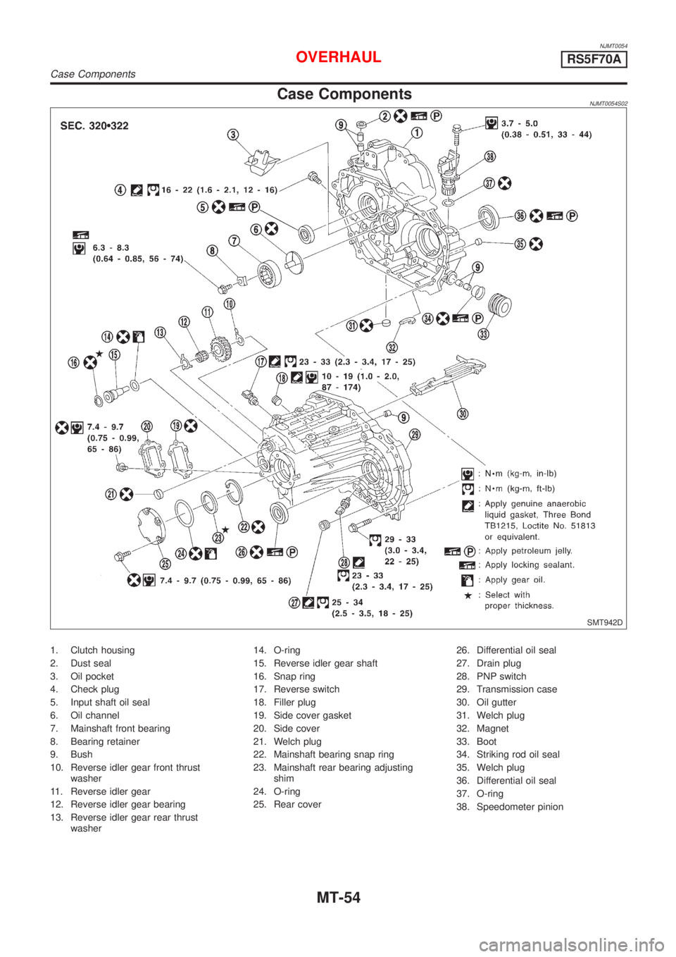
Case ComponentsNJMT0054S02
SMT942D
1. Clutch housing
2. Dust seal
3. Oil pocket
4. Check plug
5. Input shaft oil seal
6. Oil channel
7. Mainshaft front bearing
8. Bearing retainer
9. Bush
10. Reverse idler gear front thrust
washer
11. Reverse idler gear
12. Reverse idler gear bearing
13. Reverse idler gear rear thrust
washer14. O-ring
15. Reverse idler gear shaft
16. Snap ring
17. Reverse switch
18. Filler plug
19. Side cover gasket
20. Side cover
21. Welch plug
22. Mainshaft bearing snap ring
23. Mainshaft rear bearing adjusting
shim
24. O-ring
25. Rear cover26. Differential oil seal
27. Drain plug
28. PNP switch
29. Transmission case
30. Oil gutter
31. Welch plug
32. Magnet
33. Boot
34. Striking rod oil seal
35. Welch plug
36. Differential oil seal
37. O-ring
38. Speedometer pinion
OVERHAULRS5F70A
Case Components
MT-54
Page 2627 of 2898
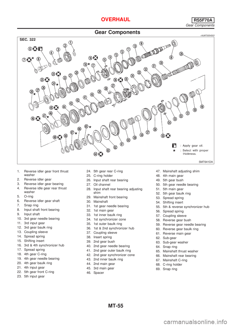
Gear Components=NJMT0054S03
SMT641DA
1. Reverse idler gear front thrust
washer
2. Reverse idler gear
3. Reverse idler gear bearing
4. Reverse idle gear rear thrust
washer
5. O-ring
6. Reverse idler gear shaft
7. Snap ring
8. Input shaft front bearing
9. Input shaft
10. 3rd gear needle bearing
11. 3rd input gear
12. 3rd gear baulk ring
13. Coupling sleeve
14. Spread spring
15. Shifting insert
16. 3rd & 4th synchronizer hub
17. Spread spring
18. 4th gear C-ring
19. 4th gear needle bearing
20. 4th gear baulk ring
21. 4th input gear
22. 5th gear front C-ring
23. 5th input gear24. 5th gear rear C-ring
25. C-ring holder
26. Input shaft rear bearing
27. Oil channel
28. Input shaft rear bearing adjusting
shim
29. Mainshaft front bearing
30. Mainshaft
31. 1st gear needle bearing
32. 1st main gear
33. 1st inner baulk ring
34. 1st synchronizer cone
35. 1st outer baulk ring
36. 1st & 2nd synchronizer hub
37. Coupling sleeve
38. Insert spring
39. 2nd gear bush
40. 2nd gear needle bearing
41. 2nd gear outer baulk ring
42. 2nd gear synchronizer cone
43. 2nd inner baulk ring
44. 2nd main gear
45. 3rd main gear
46. Spacer47. Mainshaft adjusting shim
48. 4th main gear
49. 5th gear bush
50. 5th gear needle bearing
51. 5th main gear
52. 5th gear baulk ring
53. Spread spring
54. Shifting insert
55. 5th & reverse synchronizer hub
56. Spread spring
57. Coupling sleeve
58. Reverse gear bush
59. Reverse gear needle bearing
60. Reverse gear baulk ring
61. Reverse main gear
62. Sub-gear
63. Sub-gear washer
64. Snap ring
65. Mainshaft thrust washer
66. Mainshaft rear bearing
67. Mainshaft C-ring
68. C-ring holder
69. Snap ring
OVERHAULRS5F70A
Gear Components
MT-55
Page 2628 of 2898
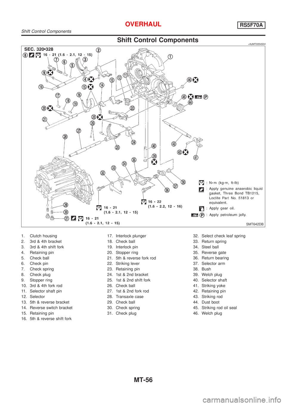
Shift Control Components=NJMT0054S04
SMT642DB
1. Clutch housing
2. 3rd & 4th bracket
3. 3rd & 4th shift fork
4. Retaining pin
5. Check ball
6. Check pin
7. Check spring
8. Check plug
9. Stopper ring
10. 3rd & 4th fork rod
11. Selector shaft pin
12. Selector
13. 5th & reverse bracket
14. Reverse switch bracket
15. Retaining pin
16. 5th & reverse shift fork17. Interlock plunger
18. Check ball
19. Interlock pin
20. Stopper ring
21. 5th & reverse fork rod
22. Striking lever
23. Retaining pin
24. 1st & 2nd bracket
25. 1st & 2nd shift fork
26. Check ball
27. 1st & 2nd fork rod
28. Transaxle case
29. Check ball
30. Check spring
31. Check plug32. Select check leaf spring
33. Return spring
34. Steel ball
35. Reverse gate
36. Return bearing
37. Selector arm
38. Bush
39. Welch plug
40. Selector shaft
41. Striking yoke
42. Retaining pin
43. Striking rod
44. Dust boot
45. Striking rod oil seal
46. Welch plug
OVERHAULRS5F70A
Shift Control Components
MT-56
Page 2629 of 2898
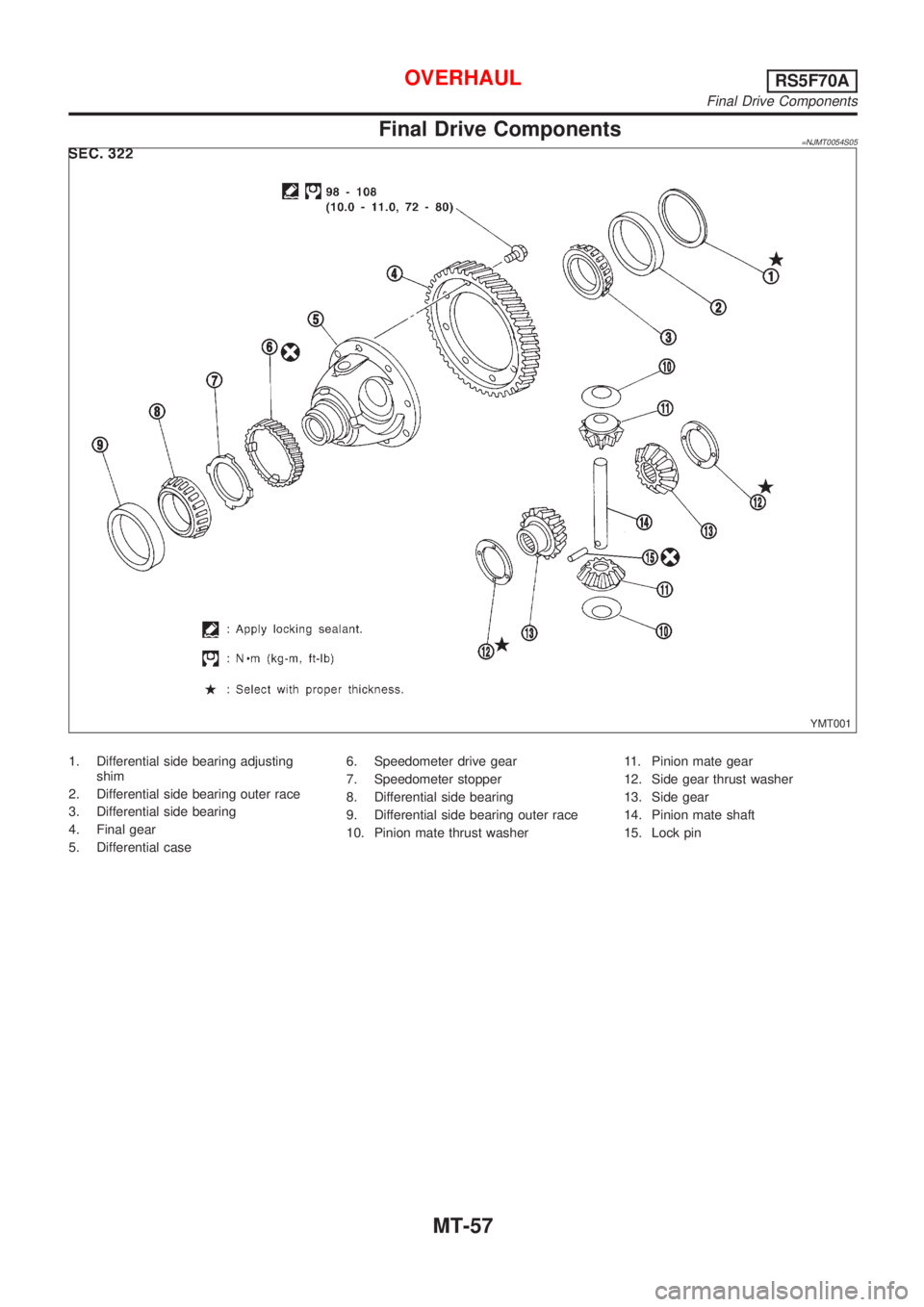
Final Drive Components=NJMT0054S05
YMT001
1. Differential side bearing adjusting
shim
2. Differential side bearing outer race
3. Differential side bearing
4. Final gear
5. Differential case6. Speedometer drive gear
7. Speedometer stopper
8. Differential side bearing
9. Differential side bearing outer race
10. Pinion mate thrust washer11. Pinion mate gear
12. Side gear thrust washer
13. Side gear
14. Pinion mate shaft
15. Lock pin
OVERHAULRS5F70A
Final Drive Components
MT-57
Page 2630 of 2898
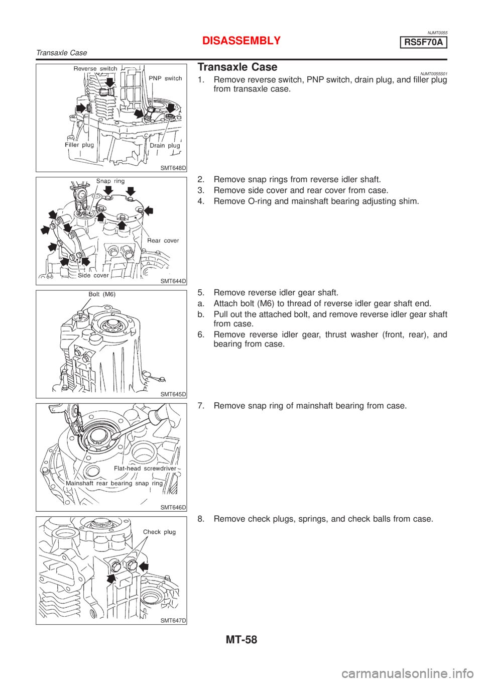
NJMT0055
SMT648D
Transaxle CaseNJMT0055S011. Remove reverse switch, PNP switch, drain plug, and filler plug
from transaxle case.
SMT644D
2. Remove snap rings from reverse idler shaft.
3. Remove side cover and rear cover from case.
4. Remove O-ring and mainshaft bearing adjusting shim.
SMT645D
5. Remove reverse idler gear shaft.
a. Attach bolt (M6) to thread of reverse idler gear shaft end.
b. Pull out the attached bolt, and remove reverse idler gear shaft
from case.
6. Remove reverse idler gear, thrust washer (front, rear), and
bearing from case.
SMT646D
7. Remove snap ring of mainshaft bearing from case.
SMT647D
8. Remove check plugs, springs, and check balls from case.
DISASSEMBLYRS5F70A
Transaxle Case
MT-58