NISSAN PICK-UP 1998 Repair Manual
Manufacturer: NISSAN, Model Year: 1998, Model line: PICK-UP, Model: NISSAN PICK-UP 1998Pages: 1659, PDF Size: 53.39 MB
Page 1001 of 1659
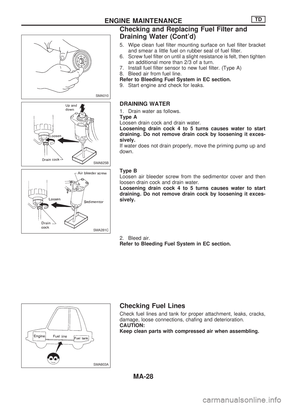
5. Wipe clean fuel filter mounting surface on fuel filter bracket
and smear a little fuel on rubber seal of fuel filter.
6. Screw fuel filter on until a slight resistance is felt, then tighten
an additional more than 2/3 of a turn.
7. Install fuel filter sensor to new fuel filter. (Type A)
8. Bleed air from fuel line.
Refer to Bleeding Fuel System in EC section.
9. Start engine and check for leaks.
DRAINING WATER
1. Drain water as follows.
Type A
Loosen drain cock and drain water.
Loosening drain cock 4 to 5 turns causes water to start
draining. Do not remove drain cock by loosening it exces-
sively.
If water does not drain properly, move the priming pump up and
down.
Type B
Loosen air bleeder screw from the sedimentor cover and then
loosen drain cock and drain water.
Loosening drain cock 4 to 5 turns causes water to start
draining. Do not remove drain cock by loosening it exces-
sively.
2. Bleed air.
Refer to Bleeding Fuel System in EC section.
Checking Fuel Lines
Check fuel lines and tank for proper attachment, leaks, cracks,
damage, loose connections, chafing and deterioration.
CAUTION:
Keep clean parts with compressed air when assembling.
SMA010
SMA825B
SMA281C
SMA803A
ENGINE MAINTENANCETD
Checking and Replacing Fuel Filter and
Draining Water (Cont'd)
MA-28
Page 1002 of 1659
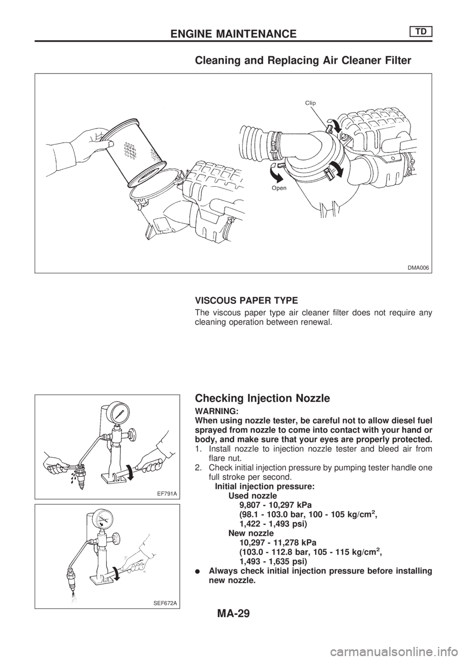
Cleaning and Replacing Air Cleaner Filter
VISCOUS PAPER TYPE
The viscous paper type air cleaner filter does not require any
cleaning operation between renewal.
Checking Injection Nozzle
WARNING:
When using nozzle tester, be careful not to allow diesel fuel
sprayed from nozzle to come into contact with your hand or
body, and make sure that your eyes are properly protected.
1. Install nozzle to injection nozzle tester and bleed air from
flare nut.
2. Check initial injection pressure by pumping tester handle one
full stroke per second.
Initial injection pressure:
Used nozzle
9,807 - 10,297 kPa
(98.1 - 103.0 bar, 100 - 105 kg/cm
2,
1,422 - 1,493 psi)
New nozzle
10,297 - 11,278 kPa
(103.0 - 112.8 bar, 105 - 115 kg/cm
2,
1,493 - 1,635 psi)
lAlways check initial injection pressure before installing
new nozzle.
DMA006
EF791A
SEF672A
ENGINE MAINTENANCETD
MA-29
Page 1003 of 1659
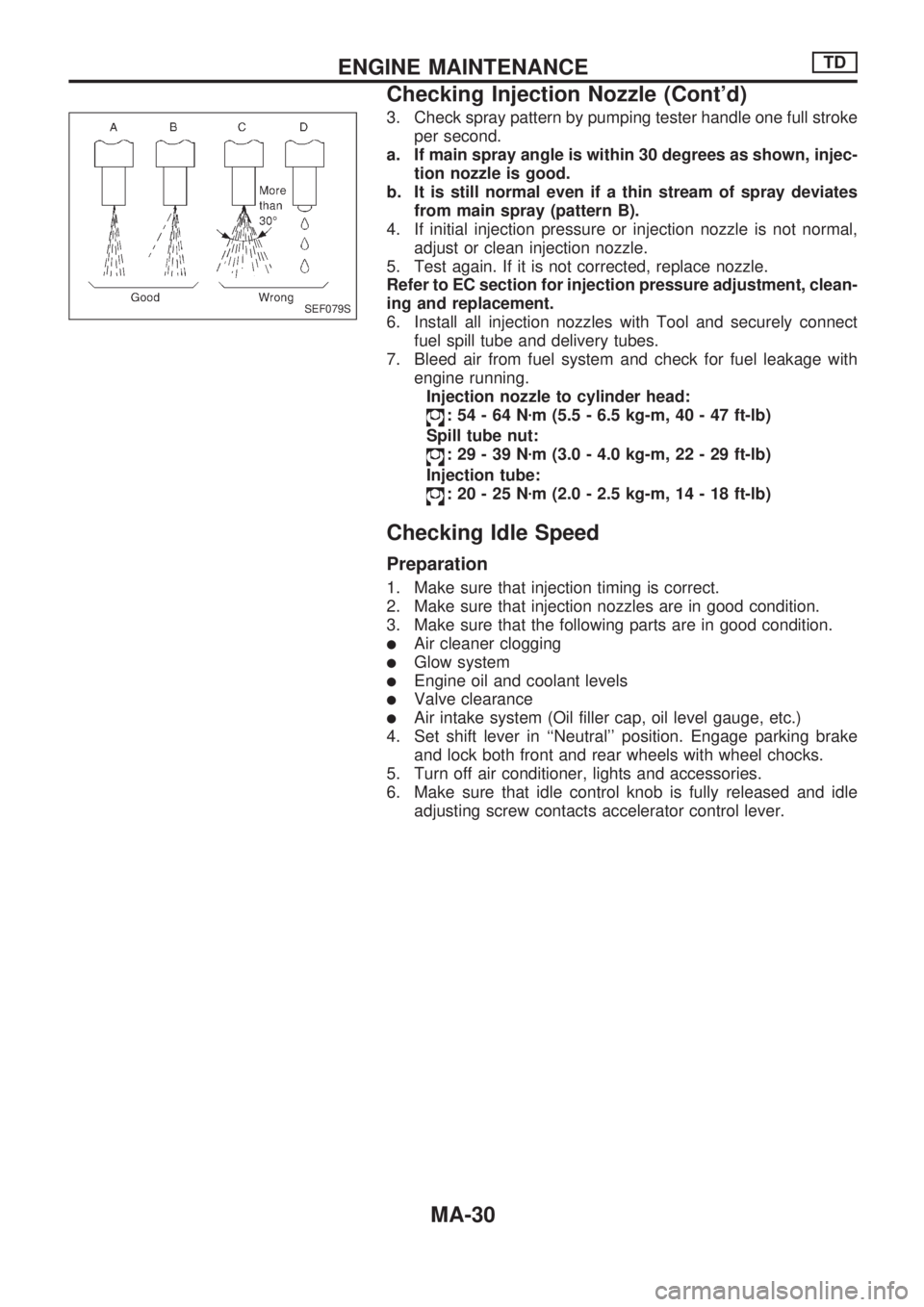
3. Check spray pattern by pumping tester handle one full stroke
per second.
a. If main spray angle is within 30 degrees as shown, injec-
tion nozzle is good.
b. It is still normal even if a thin stream of spray deviates
from main spray (pattern B).
4. If initial injection pressure or injection nozzle is not normal,
adjust or clean injection nozzle.
5. Test again. If it is not corrected, replace nozzle.
Refer to EC section for injection pressure adjustment, clean-
ing and replacement.
6. Install all injection nozzles with Tool and securely connect
fuel spill tube and delivery tubes.
7. Bleed air from fuel system and check for fuel leakage with
engine running.
Injection nozzle to cylinder head:
:54-64Nzm (5.5 - 6.5 kg-m, 40 - 47 ft-lb)
Spill tube nut:
:29-39Nzm (3.0 - 4.0 kg-m, 22 - 29 ft-lb)
Injection tube:
:20-25Nzm (2.0 - 2.5 kg-m, 14 - 18 ft-lb)
Checking Idle Speed
Preparation
1. Make sure that injection timing is correct.
2. Make sure that injection nozzles are in good condition.
3. Make sure that the following parts are in good condition.
lAir cleaner clogging
lGlow system
lEngine oil and coolant levels
lValve clearance
lAir intake system (Oil filler cap, oil level gauge, etc.)
4. Set shift lever in ``Neutral'' position. Engage parking brake
and lock both front and rear wheels with wheel chocks.
5. Turn off air conditioner, lights and accessories.
6. Make sure that idle control knob is fully released and idle
adjusting screw contacts accelerator control lever.
SEF079S
ENGINE MAINTENANCETD
Checking Injection Nozzle (Cont'd)
MA-30
Page 1004 of 1659
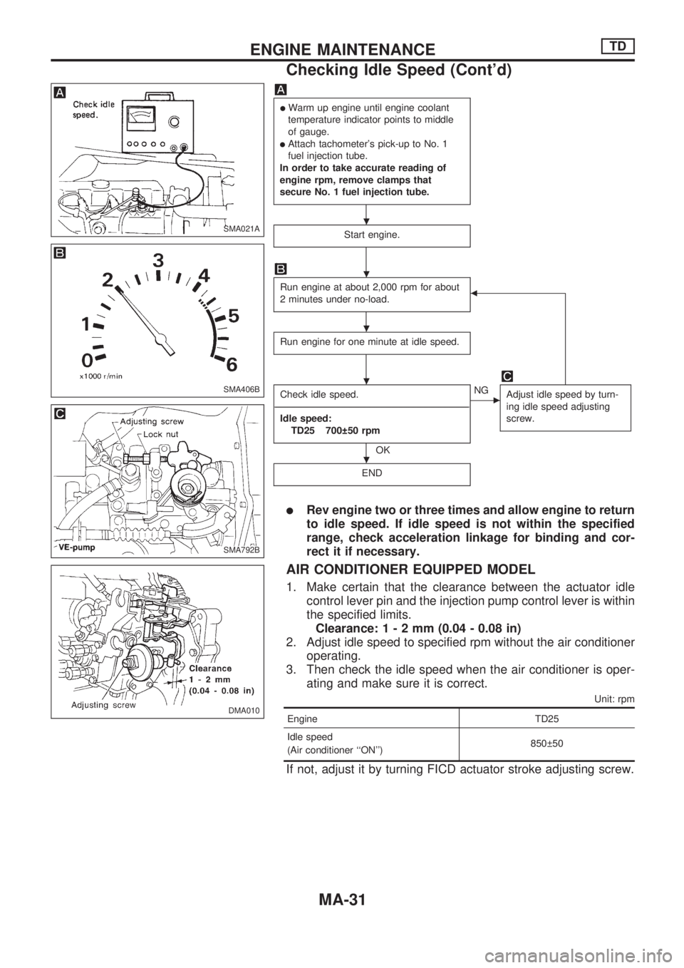
lWarm up engine until engine coolant
temperature indicator points to middle
of gauge.
lAttach tachometer's pick-up to No. 1
fuel injection tube.
In order to take accurate reading of
engine rpm, remove clamps that
secure No. 1 fuel injection tube.
Start engine.
Run engine at about 2,000 rpm for about
2 minutes under no-load.b
Run engine for one minute at idle speed.
Check idle speed.
--------------------------------------------------------------------------------------------------------------------------------------------------------------------------------------------------------------------------------------------------------------------------------------------------------
Idle speed:
TD25 700 50 rpm
OK
cNG
Adjust idle speed by turn-
ing idle speed adjusting
screw.
END
lRev engine two or three times and allow engine to return
to idle speed. If idle speed is not within the specified
range, check acceleration linkage for binding and cor-
rect it if necessary.
AIR CONDITIONER EQUIPPED MODEL
1. Make certain that the clearance between the actuator idle
control lever pin and the injection pump control lever is within
the specified limits.
Clearance:1-2mm(0.04 - 0.08 in)
2. Adjust idle speed to specified rpm without the air conditioner
operating.
3. Then check the idle speed when the air conditioner is oper-
ating and make sure it is correct.
Unit: rpm
Engine TD25
Idle speed
(Air conditioner ``ON'')850 50
If not, adjust it by turning FICD actuator stroke adjusting screw.
SMA021A
SMA406B
SMA792B
DMA010
.
.
.
.
.
ENGINE MAINTENANCETD
Checking Idle Speed (Cont'd)
MA-31
Page 1005 of 1659
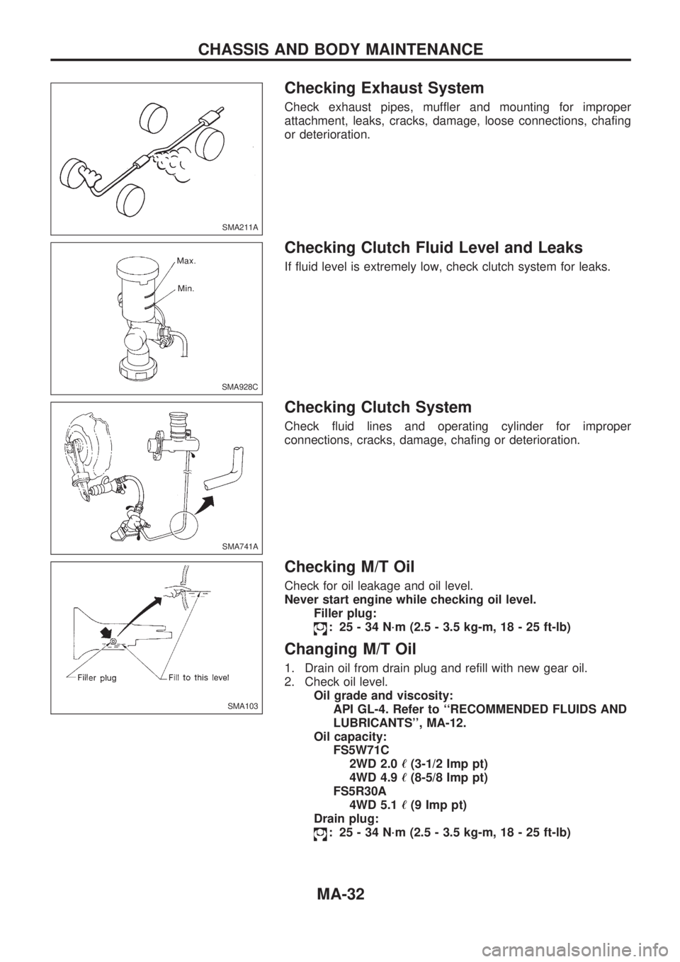
Checking Exhaust System
Check exhaust pipes, muffler and mounting for improper
attachment, leaks, cracks, damage, loose connections, chafing
or deterioration.
Checking Clutch Fluid Level and Leaks
If fluid level is extremely low, check clutch system for leaks.
Checking Clutch System
Check fluid lines and operating cylinder for improper
connections, cracks, damage, chafing or deterioration.
Checking M/T Oil
Check for oil leakage and oil level.
Never start engine while checking oil level.
Filler plug:
: 25 - 34 N´m (2.5 - 3.5 kg-m, 18 - 25 ft-lb)
Changing M/T Oil
1. Drain oil from drain plug and refill with new gear oil.
2. Check oil level.
Oil grade and viscosity:
API GL-4. Refer to ``RECOMMENDED FLUIDS AND
LUBRICANTS'', MA-12.
Oil capacity:
FS5W71C
2WD 2.0ø(3-1/2 Imp pt)
4WD 4.9ø(8-5/8 Imp pt)
FS5R30A
4WD 5.1ø(9 Imp pt)
Drain plug:
: 25 - 34 N´m (2.5 - 3.5 kg-m, 18 - 25 ft-lb)
SMA211A
SMA928C
SMA741A
SMA103
CHASSIS AND BODY MAINTENANCE
MA-32
Page 1006 of 1659
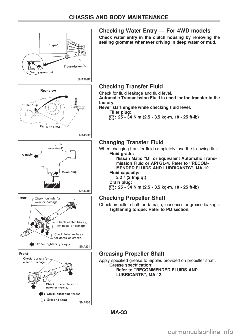
Checking Water Entry Ð For 4WD models
Check water entry in the clutch housing by removing the
sealing grommet whenever driving in deep water or mud.
Checking Transfer Fluid
Check for fluid leakage and fluid level.
Automatic Transmission Fluid is used for the transfer in the
factory.
Never start engine while checking fluid level.
Filler plug:
: 25 - 34 N´m (2.5 - 3.5 kg-m, 18 - 25 ft-lb)
Changing Transfer Fluid
When changing transfer fluid completely, use the following fluid.
Fluid grade:
Nissan Matic ``D'' or Equivalent Automatic Trans-
mission Fluid or API GL-4. Refer to ``RECOM-
MENDED FLUIDS AND LUBRICANTS'', MA-12.
Fluid capacity:
2.2ø(2 Imp qt)
Drain plug:
: 25 - 34 N´m (2.5 - 3.5 kg-m, 18 - 25 ft-lb)
Checking Propeller Shaft
Check propeller shaft for damage, looseness or grease leakage.
Tightening torque: Refer to PD section.
Greasing Propeller Shaft
Apply specified grease to nipples provided on propeller shaft.
Grease specification:
Refer to ``RECOMMENDED FLUIDS AND
LUBRICANTS'', MA-12.
SMA369B
SMA439B
SMA444B
SMA231
SMA566
CHASSIS AND BODY MAINTENANCE
MA-33
Page 1007 of 1659
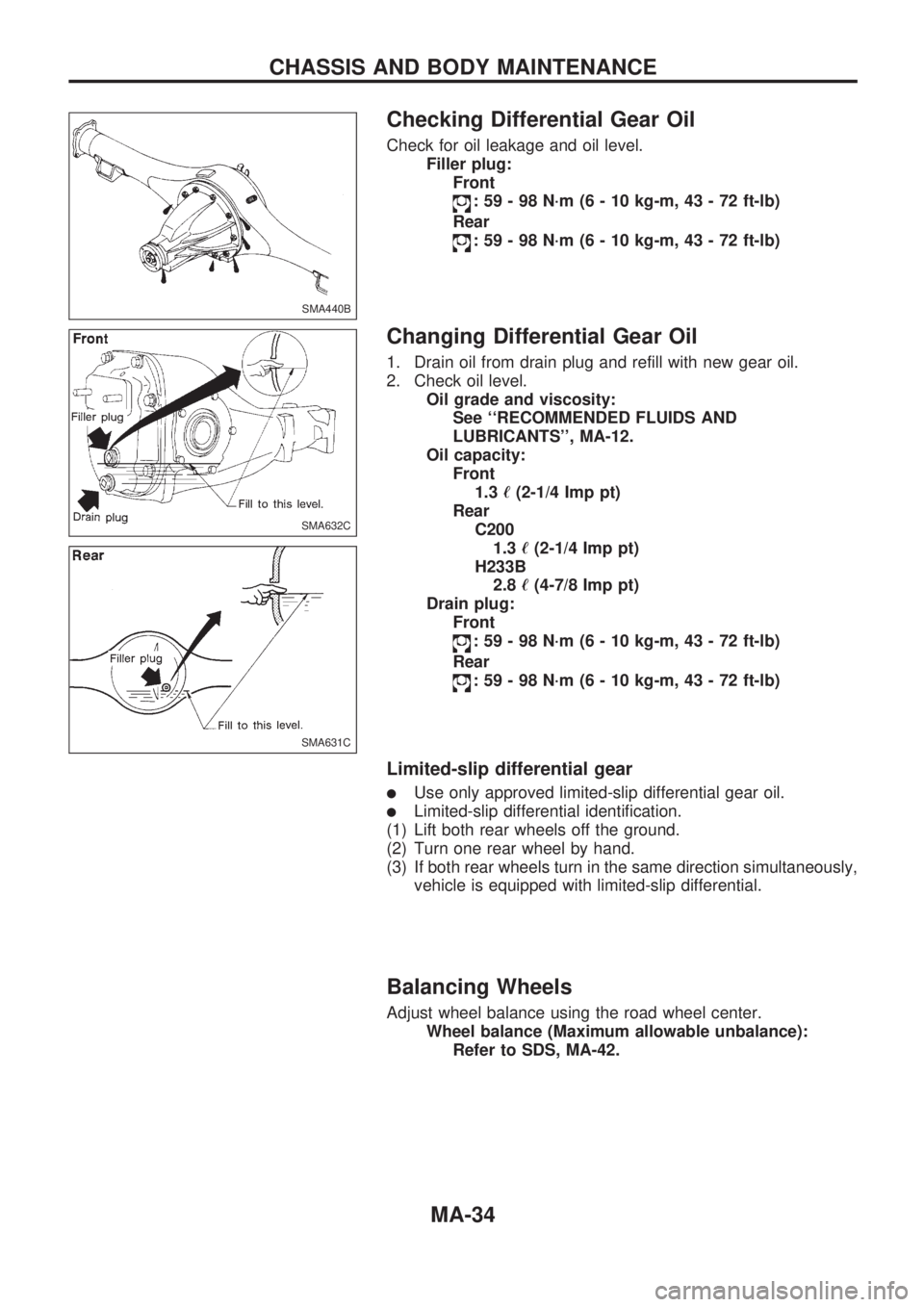
Checking Differential Gear Oil
Check for oil leakage and oil level.
Filler plug:
Front
: 59 - 98 N´m (6 - 10 kg-m, 43 - 72 ft-lb)
Rear
: 59 - 98 N´m (6 - 10 kg-m, 43 - 72 ft-lb)
Changing Differential Gear Oil
1. Drain oil from drain plug and refill with new gear oil.
2. Check oil level.
Oil grade and viscosity:
See ``RECOMMENDED FLUIDS AND
LUBRICANTS'', MA-12.
Oil capacity:
Front
1.3ø(2-1/4 Imp pt)
Rear
C200
1.3ø(2-1/4 Imp pt)
H233B
2.8ø(4-7/8 Imp pt)
Drain plug:
Front
: 59 - 98 N´m (6 - 10 kg-m, 43 - 72 ft-lb)
Rear
: 59 - 98 N´m (6 - 10 kg-m, 43 - 72 ft-lb)
Limited-slip differential gear
lUse only approved limited-slip differential gear oil.
lLimited-slip differential identification.
(1) Lift both rear wheels off the ground.
(2) Turn one rear wheel by hand.
(3) If both rear wheels turn in the same direction simultaneously,
vehicle is equipped with limited-slip differential.
Balancing Wheels
Adjust wheel balance using the road wheel center.
Wheel balance (Maximum allowable unbalance):
Refer to SDS, MA-42.
SMA440B
SMA632C
SMA631C
CHASSIS AND BODY MAINTENANCE
MA-34
Page 1008 of 1659
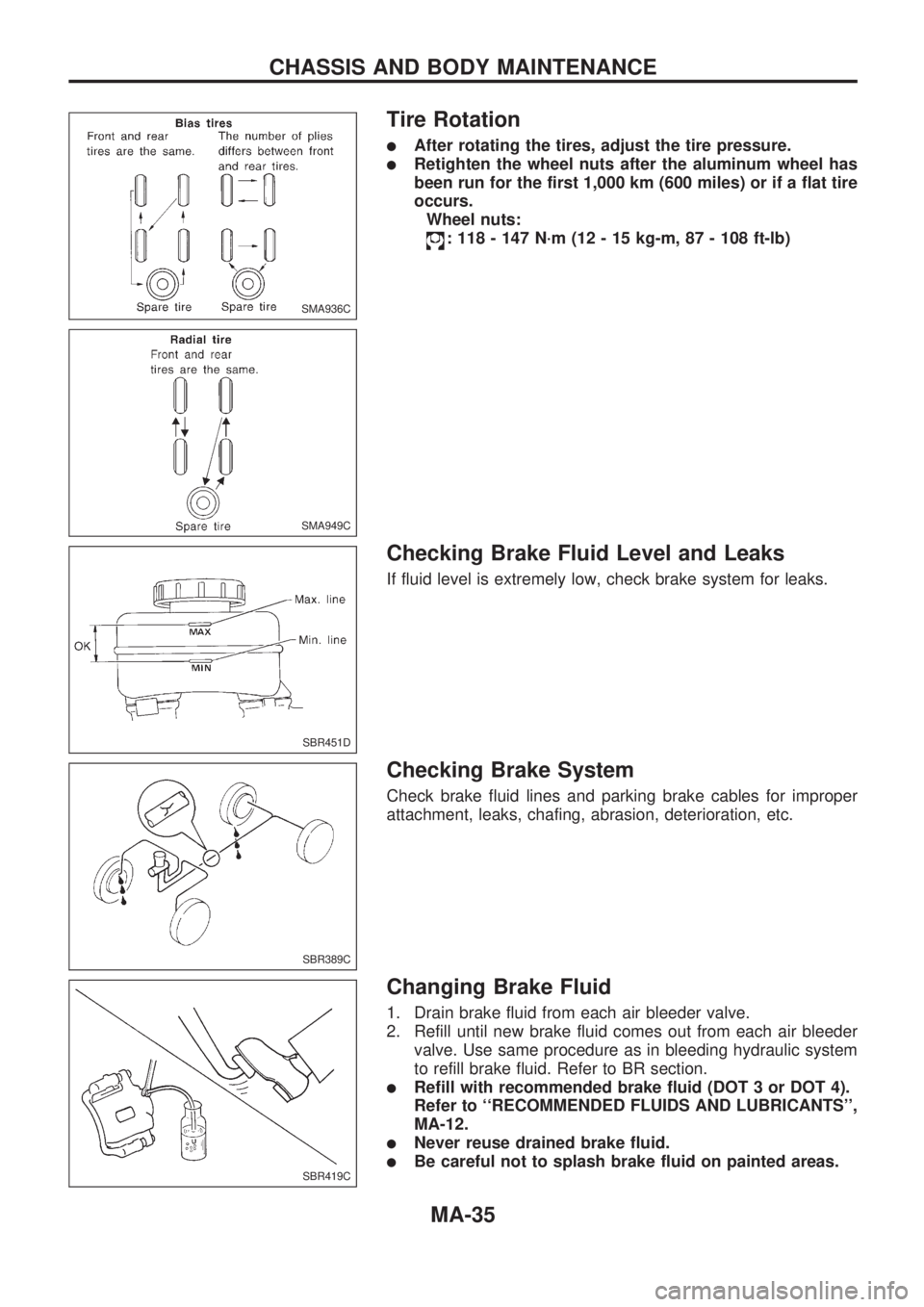
Tire Rotation
lAfter rotating the tires, adjust the tire pressure.
lRetighten the wheel nuts after the aluminum wheel has
been run for the first 1,000 km (600 miles) or if a flat tire
occurs.
Wheel nuts:
: 118 - 147 N´m (12 - 15 kg-m, 87 - 108 ft-lb)
Checking Brake Fluid Level and Leaks
If fluid level is extremely low, check brake system for leaks.
Checking Brake System
Check brake fluid lines and parking brake cables for improper
attachment, leaks, chafing, abrasion, deterioration, etc.
Changing Brake Fluid
1. Drain brake fluid from each air bleeder valve.
2. Refill until new brake fluid comes out from each air bleeder
valve. Use same procedure as in bleeding hydraulic system
to refill brake fluid. Refer to BR section.
lRefill with recommended brake fluid (DOT 3 or DOT 4).
Refer to ``RECOMMENDED FLUIDS AND LUBRICANTS'',
MA-12.
lNever reuse drained brake fluid.
lBe careful not to splash brake fluid on painted areas.
SMA936C
SMA949C
SBR451D
SBR389C
SBR419C
CHASSIS AND BODY MAINTENANCE
MA-35
Page 1009 of 1659
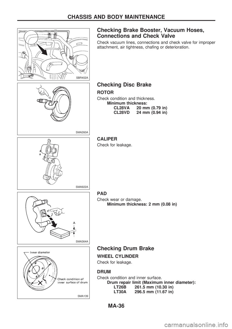
Checking Brake Booster, Vacuum Hoses,
Connections and Check Valve
Check vacuum lines, connections and check valve for improper
attachment, air tightness, chafing or deterioration.
Checking Disc Brake
ROTOR
Check condition and thickness.
Minimum thickness:
CL28VA 20 mm (0.79 in)
CL28VD 24 mm (0.94 in)
CALIPER
Check for leakage.
PAD
Check wear or damage.
Minimum thickness: 2 mm (0.08 in)
Checking Drum Brake
WHEEL CYLINDER
Check for leakage.
DRUM
Check condition and inner surface.
Drum repair limit (Maximum inner diameter):
LT26B 261.5 mm (10.30 in)
LT30A 296.5 mm (11.67 in)
SBR402A
SMA260A
SMA922A
SMA364A
SMA139
CHASSIS AND BODY MAINTENANCE
MA-36
Page 1010 of 1659
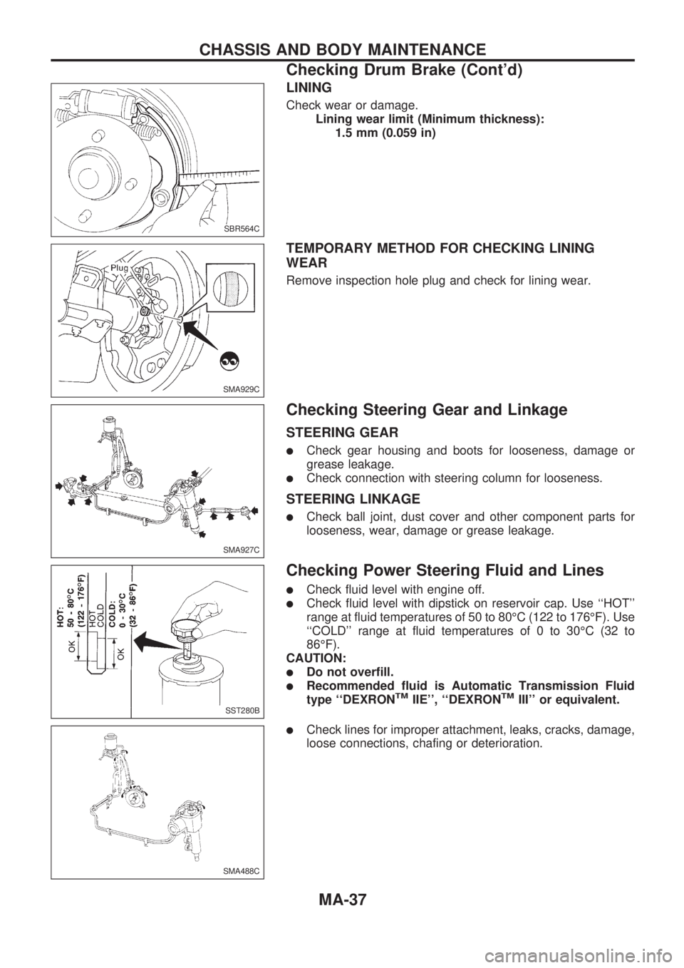
LINING
Check wear or damage.
Lining wear limit (Minimum thickness):
1.5 mm (0.059 in)
TEMPORARY METHOD FOR CHECKING LINING
WEAR
Remove inspection hole plug and check for lining wear.
Checking Steering Gear and Linkage
STEERING GEAR
lCheck gear housing and boots for looseness, damage or
grease leakage.
lCheck connection with steering column for looseness.
STEERING LINKAGE
lCheck ball joint, dust cover and other component parts for
looseness, wear, damage or grease leakage.
Checking Power Steering Fluid and Lines
lCheck fluid level with engine off.
lCheck fluid level with dipstick on reservoir cap. Use ``HOT''
range at fluid temperatures of 50 to 80ÉC (122 to 176ÉF). Use
``COLD'' range at fluid temperatures of 0 to 30ÉC (32 to
86ÉF).
CAUTION:
lDo not overfill.
lRecommended fluid is Automatic Transmission Fluid
type ``DEXRONTMIIE'', ``DEXRONTMIII'' or equivalent.
lCheck lines for improper attachment, leaks, cracks, damage,
loose connections, chafing or deterioration.
SBR564C
SMA929C
SMA927C
SST280B
SMA488C
CHASSIS AND BODY MAINTENANCE
Checking Drum Brake (Cont'd)
MA-37