NISSAN PICK-UP 1998 Repair Manual
Manufacturer: NISSAN, Model Year: 1998, Model line: PICK-UP, Model: NISSAN PICK-UP 1998Pages: 1659, PDF Size: 53.39 MB
Page 1011 of 1659
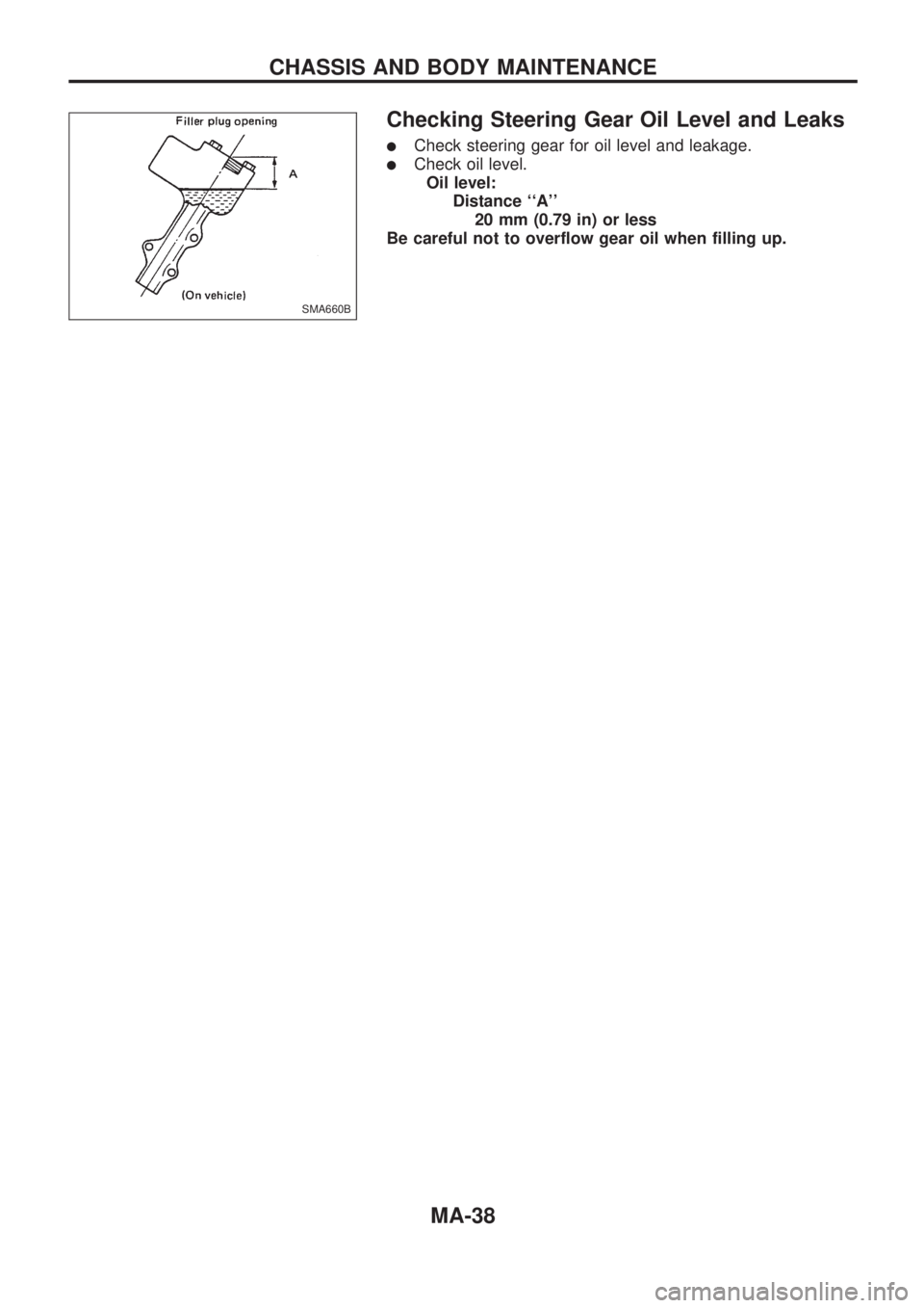
Checking Steering Gear Oil Level and Leaks
lCheck steering gear for oil level and leakage.
lCheck oil level.
Oil level:
Distance ``A''
20 mm (0.79 in) or less
Be careful not to overflow gear oil when filling up.
SMA660B
CHASSIS AND BODY MAINTENANCE
MA-38
Page 1012 of 1659
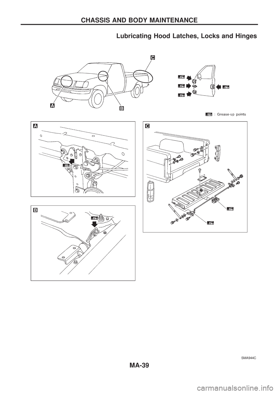
Lubricating Hood Latches, Locks and Hinges
SMA944C
CHASSIS AND BODY MAINTENANCE
MA-39
Page 1013 of 1659
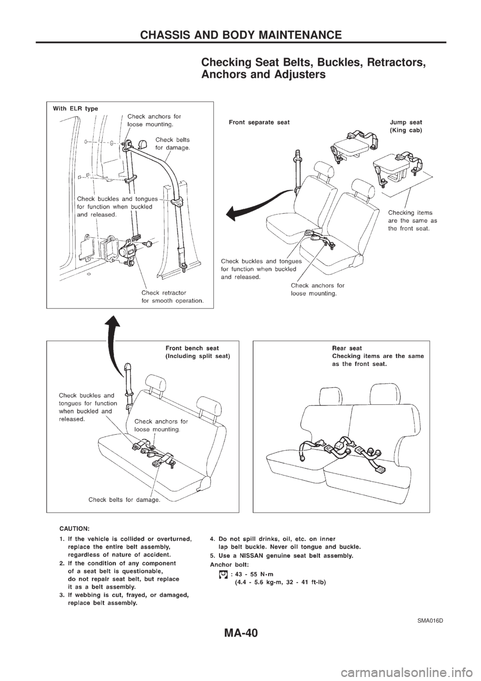
Checking Seat Belts, Buckles, Retractors,
Anchors and Adjusters
SMA016D
CHASSIS AND BODY MAINTENANCE
MA-40
Page 1014 of 1659
Checking Body Corrosion
Visually check the body sheet metal panel for corrosion, paint damage (scratches, chipping, rubbing, etc.)
or damage to the anti-corrosion materials. In particular, check the following locations.
Hemmed portion
Hood front end, door lower end, trunk lid rear end, etc.
Panel joint
Side sill of rear fender and center pillar, rear wheel housing of rear fender, around strut tower in engine
compartment, etc.
Panel edge
Trunk lid opening, sunroof opening, fender wheelarch flange, fuel filler lid flange, around holes in panel, etc.
Parts contact
Waist molding, windshield molding, bumper, etc.
Protectors
Damage or condition of mudguard, fender protector, chipping protector, etc.
Anti-corrosion materials
Damage or separation of anti-corrosion materials under the body.
Drain holes
Condition of drain holes at door and side sill.
When repairing corroded areas, refer to the Corrosion Repair Manual.
CHASSIS AND BODY MAINTENANCE
MA-41
Page 1015 of 1659
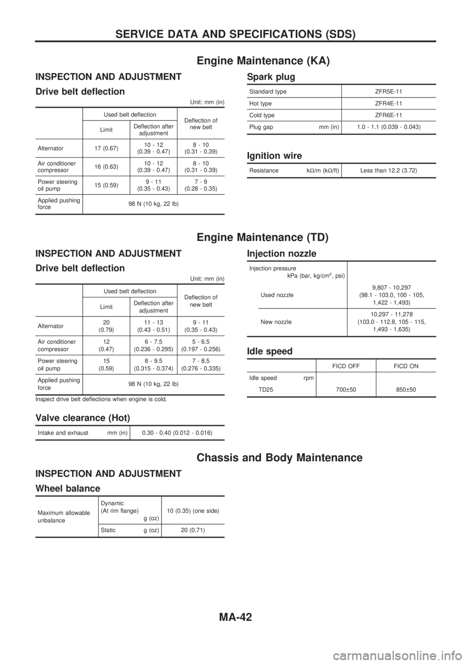
Engine Maintenance (KA)
INSPECTION AND ADJUSTMENT
Drive belt deflection
Unit: mm (in)
Used belt deflection
Deflection of
new belt
LimitDeflection after
adjustment
Alternator 17 (0.67)10-12
(0.39 - 0.47)8-10
(0.31 - 0.39)
Air conditioner
compressor16 (0.63)10-12
(0.39 - 0.47)8-10
(0.31 - 0.39)
Power steering
oil pump15 (0.59)9-11
(0.35 - 0.43)7-9
(0.28 - 0.35)
Applied pushing
force98 N (10 kg, 22 lb)
Spark plug
Standard type ZFR5E-11
Hot type ZFR4E-11
Cold type ZFR6E-11
Plug gap mm (in) 1.0 - 1.1 (0.039 - 0.043)
Ignition wire
Resistance kW/m (kW/ft) Less than 12.2 (3.72)
Engine Maintenance (TD)
INSPECTION AND ADJUSTMENT
Drive belt deflection
Unit: mm (in)
Used belt deflection
Deflection of
new belt
LimitDeflection after
adjustment
Alternator20
(0.79)11-13
(0.43 - 0.51)9-11
(0.35 - 0.43)
Air conditioner
compressor12
(0.47)6 - 7.5
(0.236 - 0.295)5 - 6.5
(0.197 - 0.256)
Power steering
oil pump15
(0.59)8 - 9.5
(0.315 - 0.374)7 - 8.5
(0.276 - 0.335)
Applied pushing
force98 N (10 kg, 22 lb)
Inspect drive belt deflections when engine is cold.
Valve clearance (Hot)
Intake and exhaust mm (in) 0.30 - 0.40 (0.012 - 0.016)
Injection nozzle
Injection pressure
kPa (bar, kg/cm2, psi)
Used nozzle9,807 - 10,297
(98.1 - 103.0, 100 - 105,
1,422 - 1,493)
New nozzle10,297 - 11,278
(103.0 - 112.8, 105 - 115,
1,493 - 1,635)
Idle speed
FICD OFF FICD ON
Idle speed rpm
TD25 700 50 850 50
Chassis and Body Maintenance
INSPECTION AND ADJUSTMENT
Wheel balance
Maximum allowable
unbalanceDynamic
(At rim flange)
g (oz)10 (0.35) (one side)
Static g (oz) 20 (0.71)
SERVICE DATA AND SPECIFICATIONS (SDS)
MA-42
Page 1016 of 1659
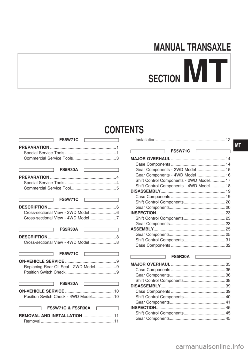
MANUALTRANSAXLESECTION
MT
CONTENTS
FS5W71C
PREPARATION ......................................................... 1
Special Service Tools ............................................ 1
Commercial Service Tools ..................................... 3
FS5R30A
PREPARATION......................................................... 4
Special Service Tools ............................................ 4
Commercial Service Tool....................................... 5
FS5W71C
DESCRIPTION........................................................... 6
Cross-sectional View - 2WD Model ....................... 6
Cross-sectional View - 4WD Model ....................... 7
FS5R30A
DESCRIPTION........................................................... 8
Cross-sectional View - 4WD Model ....................... 8
FS5W71C
ON-VEHICLE SERVICE ............................................ 9
Replacing Rear Oil Seal - 2WD Model.................. 9
Position Switch Check ........................................... 9
FS5R30A
ON-VEHICLE SERVICE .......................................... 10
Position Switch Check - 4WD Model................... 10
FS5W71C & FS5R30A
REMOVAL AND INSTALLATION ........................... 11
Removal ............................................................... 11 Installation ............................................................ 12
FS5W71C
MAJOR OVERHAUL ............................................... 14
Case Components ............................................... 14
Gear Components - 2WD Model ......................... 15
Gear Components - 4WD Model ......................... 16
Shift Control Components - 2WD Model ............. 17
Shift Control Components - 4WD Model ............. 18
DISASSEMBLY ........................................................ 19
Case Components ............................................... 19
Shift Control Components.................................... 20
Gear Components................................................ 20
INSPECTION ............................................................ 23
Shift Control Components.................................... 23
Gear Components................................................ 23
ASSEMBLY .............................................................. 25
Gear Components................................................ 25
Shift Control Components.................................... 31
Case Components ............................................... 32
FS5R30A
MAJOR OVERHAUL ............................................... 35
Case Components ............................................... 35
Gear Components................................................ 36
Shift Control Components.................................... 38
DISASSEMBLY ........................................................ 39
Case Components ............................................... 39
Shift Control Components.................................... 40
Gear Components................................................ 41
INSPECTION ............................................................ 45
Shift Control Components.................................... 45
Gear Components................................................ 45
MT
Page 1017 of 1659
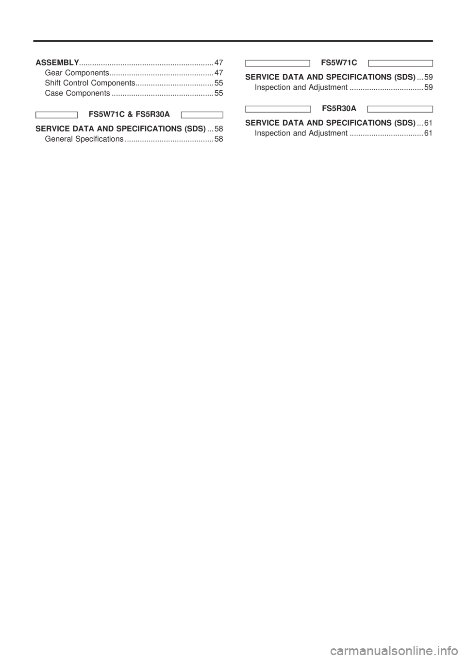
ASSEMBLY.............................................................. 47
Gear Components................................................ 47
Shift Control Components.................................... 55
Case Components ............................................... 55
FS5W71C & FS5R30A
SERVICE DATA AND SPECIFICATIONS (SDS)... 58
General Specifications ......................................... 58FS5W71C
SERVICE DATA AND SPECIFICATIONS (SDS)... 59
Inspection and Adjustment .................................. 59
FS5R30A
SERVICE DATA AND SPECIFICATIONS (SDS)... 61
Inspection and Adjustment .................................. 61
Page 1018 of 1659
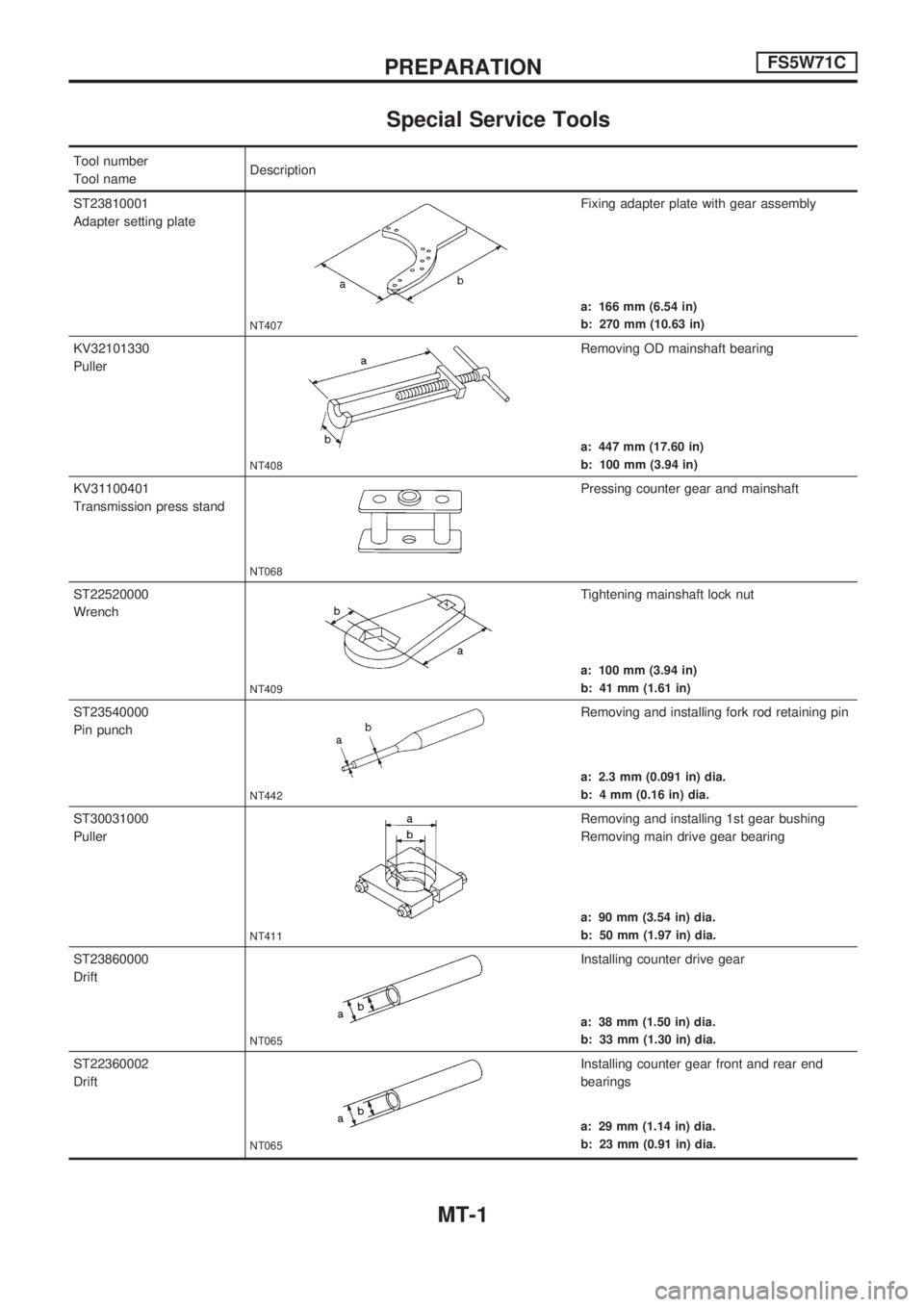
Special Service Tools
Tool number
Tool nameDescription
ST23810001
Adapter setting plate
NT407
Fixing adapter plate with gear assembly
a: 166 mm (6.54 in)
b: 270 mm (10.63 in)
KV32101330
Puller
NT408
Removing OD mainshaft bearing
a: 447 mm (17.60 in)
b: 100 mm (3.94 in)
KV31100401
Transmission press stand
NT068
Pressing counter gear and mainshaft
ST22520000
Wrench
NT409
Tightening mainshaft lock nut
a: 100 mm (3.94 in)
b: 41 mm (1.61 in)
ST23540000
Pin punch
NT442
Removing and installing fork rod retaining pin
a: 2.3 mm (0.091 in) dia.
b: 4 mm (0.16 in) dia.
ST30031000
Puller
NT411
Removing and installing 1st gear bushing
Removing main drive gear bearing
a: 90 mm (3.54 in) dia.
b: 50 mm (1.97 in) dia.
ST23860000
Drift
NT065
Installing counter drive gear
a: 38 mm (1.50 in) dia.
b: 33 mm (1.30 in) dia.
ST22360002
Drift
NT065
Installing counter gear front and rear end
bearings
a: 29 mm (1.14 in) dia.
b: 23 mm (0.91 in) dia.
PREPARATIONFS5W71C
MT-1
Page 1019 of 1659
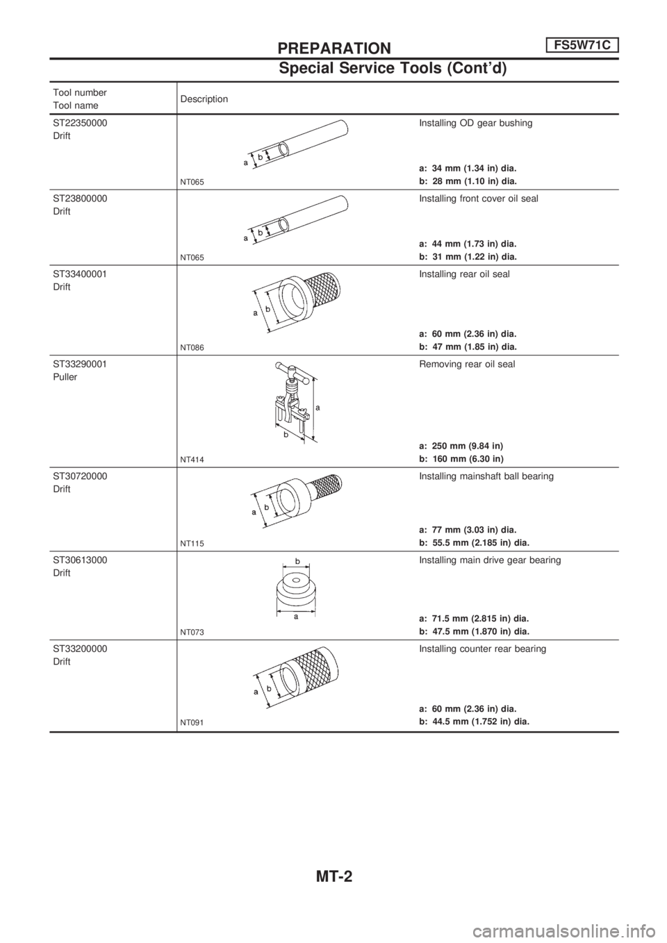
Tool number
Tool nameDescription
ST22350000
Drift
NT065
Installing OD gear bushing
a: 34 mm (1.34 in) dia.
b: 28 mm (1.10 in) dia.
ST23800000
Drift
NT065
Installing front cover oil seal
a: 44 mm (1.73 in) dia.
b: 31 mm (1.22 in) dia.
ST33400001
Drift
NT086
Installing rear oil seal
a: 60 mm (2.36 in) dia.
b: 47 mm (1.85 in) dia.
ST33290001
Puller
NT414
Removing rear oil seal
a: 250 mm (9.84 in)
b: 160 mm (6.30 in)
ST30720000
Drift
NT115
Installing mainshaft ball bearing
a: 77 mm (3.03 in) dia.
b: 55.5 mm (2.185 in) dia.
ST30613000
Drift
NT073
Installing main drive gear bearing
a: 71.5 mm (2.815 in) dia.
b: 47.5 mm (1.870 in) dia.
ST33200000
Drift
NT091
Installing counter rear bearing
a: 60 mm (2.36 in) dia.
b: 44.5 mm (1.752 in) dia.
PREPARATIONFS5W71C
Special Service Tools (Cont'd)
MT-2
Page 1020 of 1659
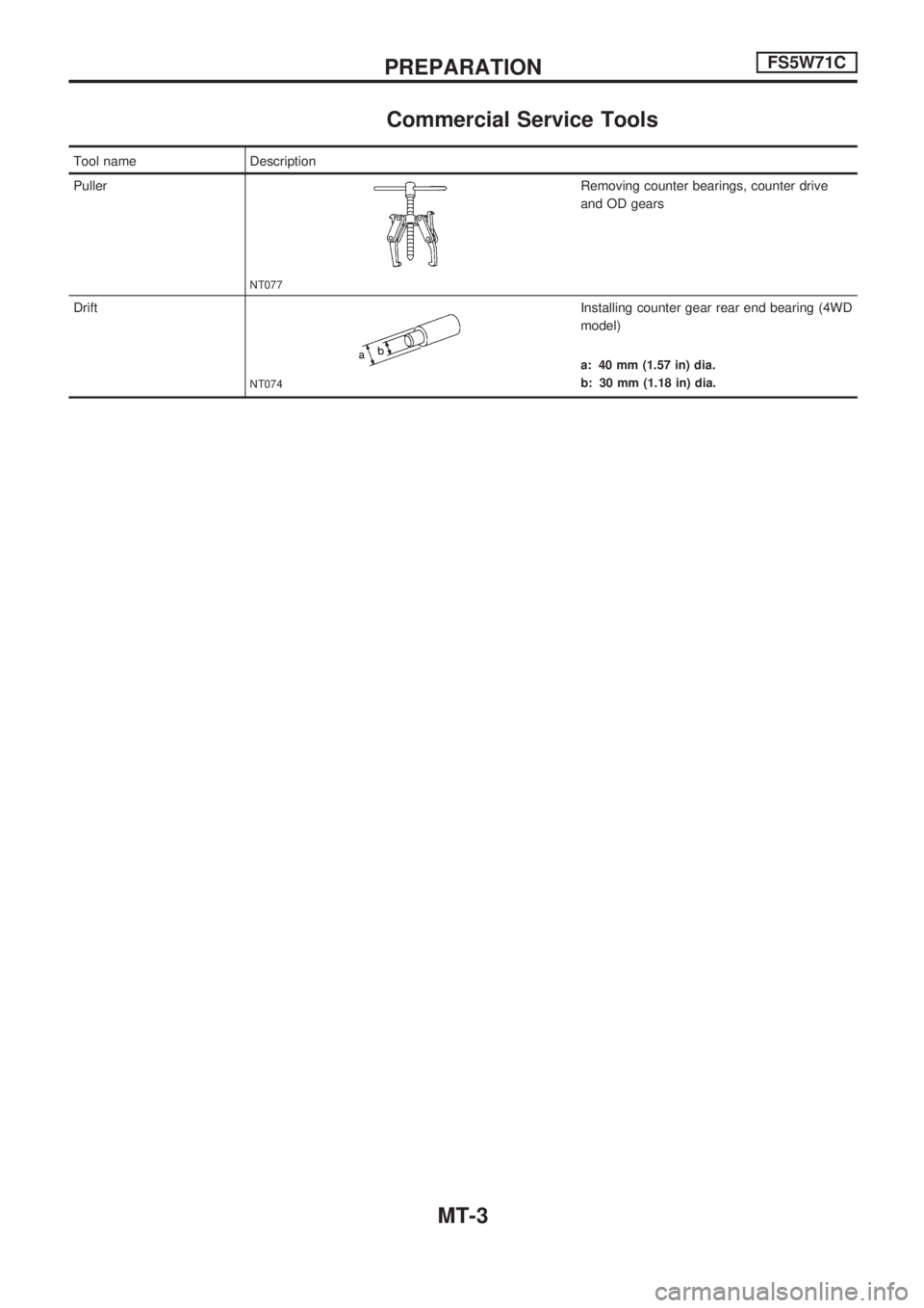
Commercial Service Tools
Tool name Description
Puller
NT077
Removing counter bearings, counter drive
and OD gears
Drift
NT074
Installing counter gear rear end bearing (4WD
model)
a: 40 mm (1.57 in) dia.
b: 30 mm (1.18 in) dia.
PREPARATIONFS5W71C
MT-3