NISSAN PICK-UP 1998 Repair Manual
PICK-UP 1998
NISSAN
NISSAN
https://www.carmanualsonline.info/img/5/57374/w960_57374-0.png
NISSAN PICK-UP 1998 Repair Manual
Trending: air conditioning, steering wheel adjustment, air filter, open gas tank, 4WD, oil, brake rotor
Page 1041 of 1659
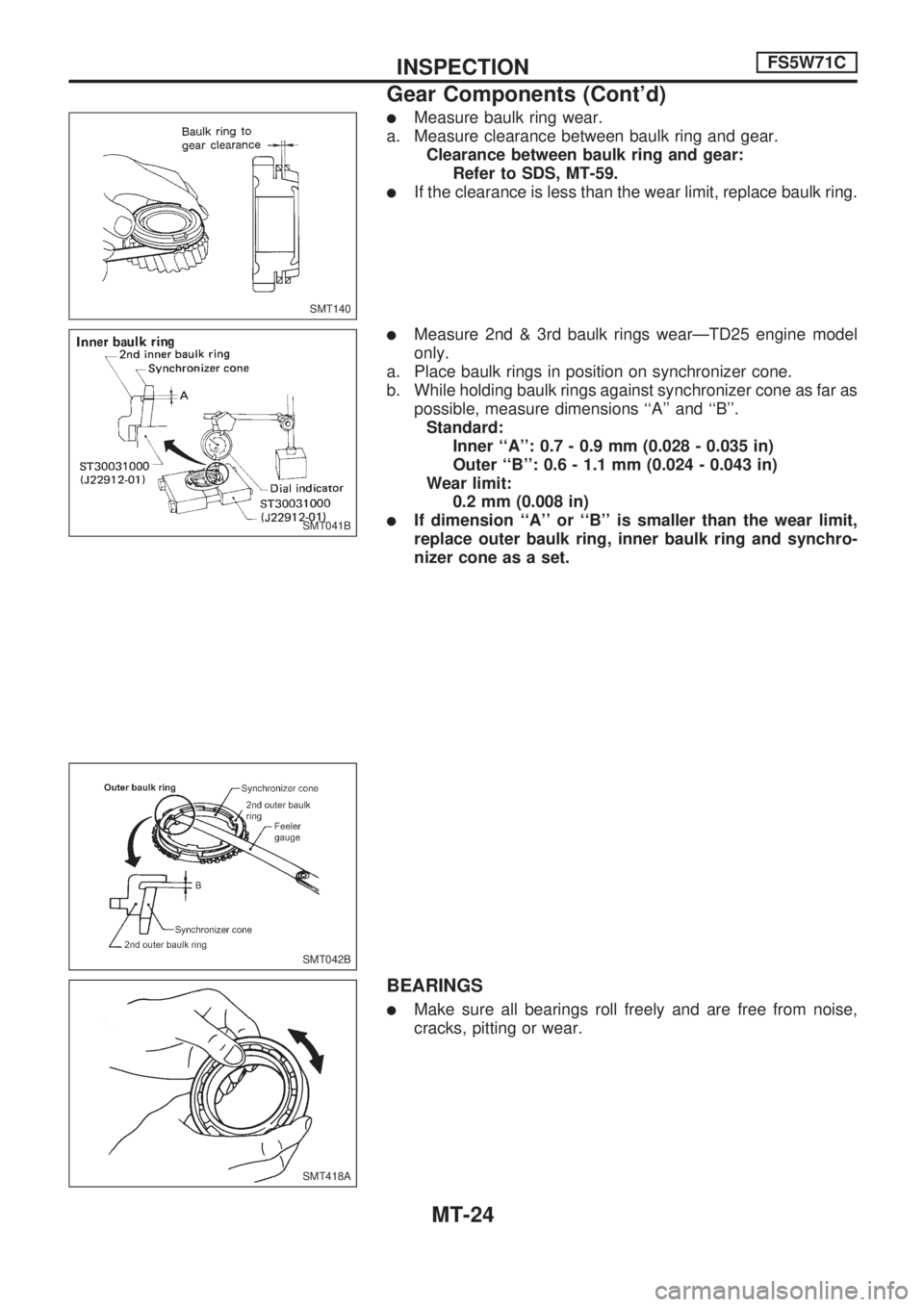
lMeasure baulk ring wear.
a. Measure clearance between baulk ring and gear.
Clearance between baulk ring and gear:
Refer to SDS, MT-59.
lIf the clearance is less than the wear limit, replace baulk ring.
lMeasure 2nd & 3rd baulk rings wearÐTD25 engine model
only.
a. Place baulk rings in position on synchronizer cone.
b. While holding baulk rings against synchronizer cone as far as
possible, measure dimensions ``A'' and ``B''.
Standard:
Inner ``A'': 0.7 - 0.9 mm (0.028 - 0.035 in)
Outer ``B'': 0.6 - 1.1 mm (0.024 - 0.043 in)
Wear limit:
0.2 mm (0.008 in)
lIf dimension ``A'' or ``B'' is smaller than the wear limit,
replace outer baulk ring, inner baulk ring and synchro-
nizer cone as a set.
BEARINGS
lMake sure all bearings roll freely and are free from noise,
cracks, pitting or wear.
SMT140
SMT041B
SMT042B
SMT418A
INSPECTIONFS5W71C
Gear Components (Cont'd)
MT-24
Page 1042 of 1659
Gear Components
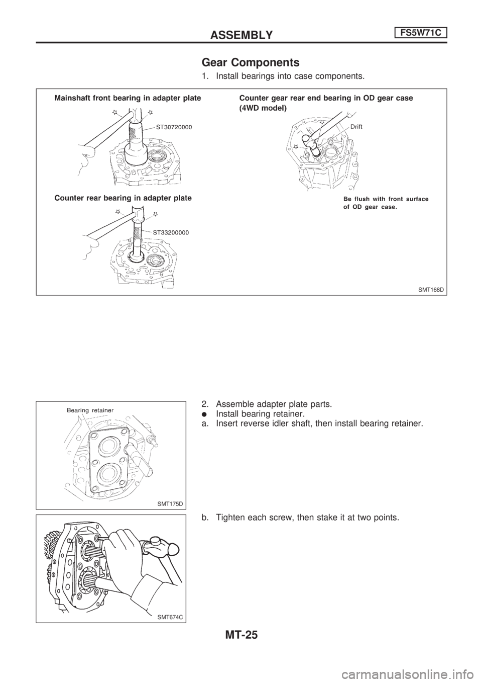
1. Install bearings into case components.
2. Assemble adapter plate parts.
lInstall bearing retainer.
a. Insert reverse idler shaft, then install bearing retainer.
b. Tighten each screw, then stake it at two points.
SMT168D
SMT175D
SMT674C
ASSEMBLYFS5W71C
MT-25
Page 1043 of 1659
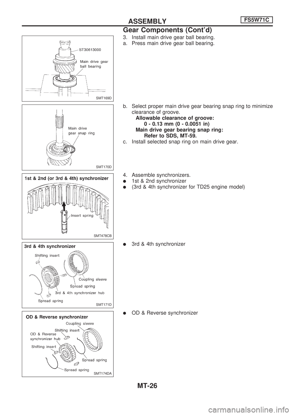
3. Install main drive gear ball bearing.
a. Press main drive gear ball bearing.
b. Select proper main drive gear bearing snap ring to minimize
clearance of groove.
Allowable clearance of groove:
0 - 0.13 mm (0 - 0.0051 in)
Main drive gear bearing snap ring:
Refer to SDS, MT-59.
c. Install selected snap ring on main drive gear.
4. Assemble synchronizers.
l1st & 2nd synchronizer
l(3rd & 4th synchronizer for TD25 engine model)
l3rd & 4th synchronizer
lOD & Reverse synchronizer
SMT169D
SMT170D
SMT478CB
SMT171D
SMT174DA
ASSEMBLYFS5W71C
Gear Components (Cont'd)
MT-26
Page 1044 of 1659
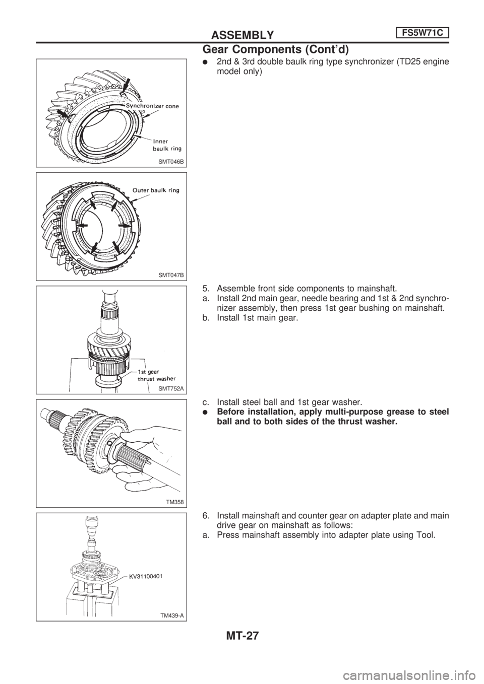
l2nd & 3rd double baulk ring type synchronizer (TD25 engine
model only)
5. Assemble front side components to mainshaft.
a. Install 2nd main gear, needle bearing and 1st & 2nd synchro-
nizer assembly, then press 1st gear bushing on mainshaft.
b. Install 1st main gear.
c. Install steel ball and 1st gear washer.
lBefore installation, apply multi-purpose grease to steel
ball and to both sides of the thrust washer.
6. Install mainshaft and counter gear on adapter plate and main
drive gear on mainshaft as follows:
a. Press mainshaft assembly into adapter plate using Tool.
SMT046B
SMT047B
SMT752A
TM358
TM439-A
ASSEMBLYFS5W71C
Gear Components (Cont'd)
MT-27
Page 1045 of 1659
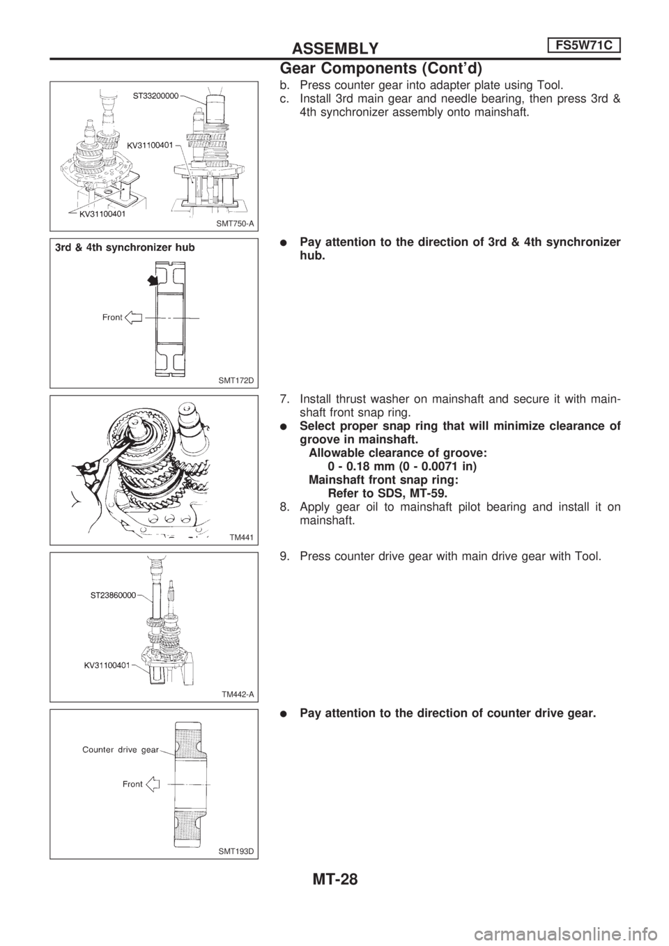
b. Press counter gear into adapter plate using Tool.
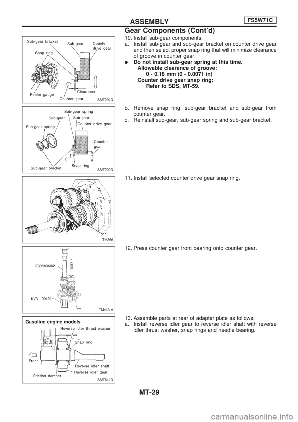
c. Install 3rd main gear and needle bearing, then press 3rd &
4th synchronizer assembly onto mainshaft.
lPay attention to the direction of 3rd & 4th synchronizer
hub.
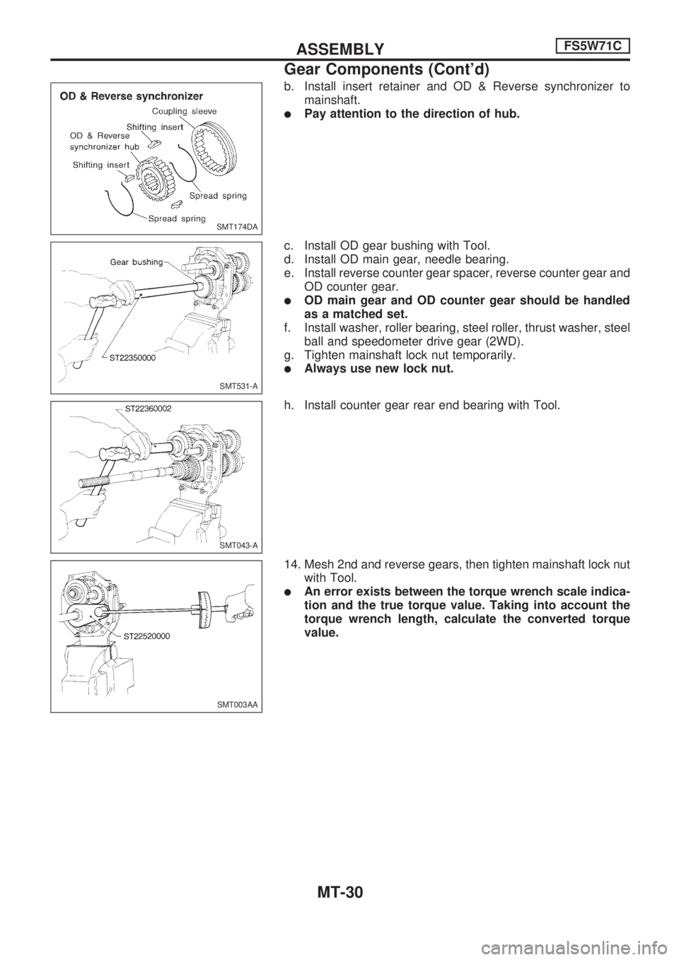
7. Install thrust washer on mainshaft and secure it with main-
shaft front snap ring.
lSelect proper snap ring that will minimize clearance of
groove in mainshaft.
Allowable clearance of groove:
0 - 0.18 mm (0 - 0.0071 in)
Mainshaft front snap ring:
Refer to SDS, MT-59.
8. Apply gear oil to mainshaft pilot bearing and install it on
mainshaft.
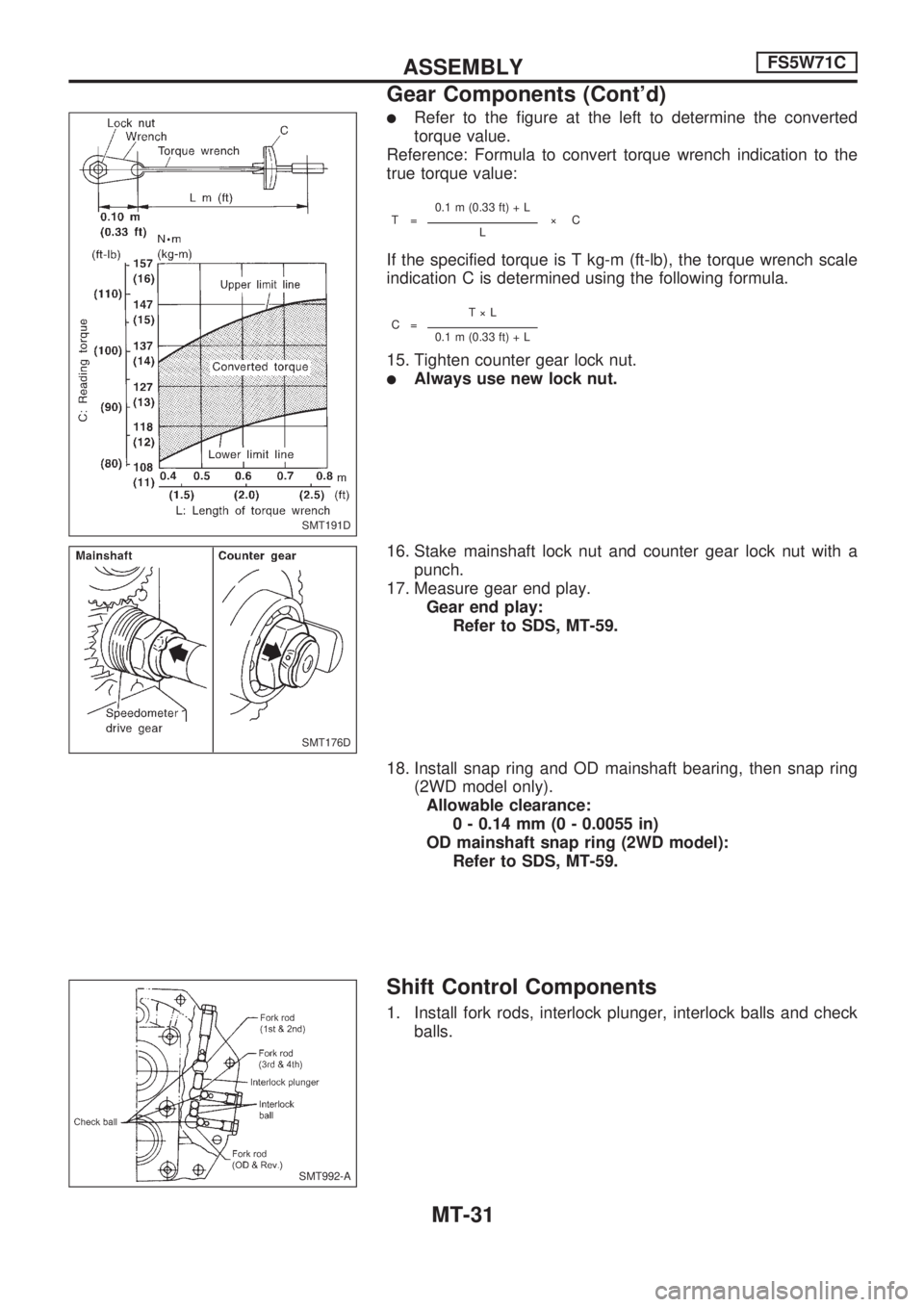
9. Press counter drive gear with main drive gear with Tool.
lPay attention to the direction of counter drive gear.
SMT750-A
SMT172D
TM441
TM442-A
SMT193D
ASSEMBLYFS5W71C
Gear Components (Cont'd)
MT-28
Page 1046 of 1659
10. Install sub-gear components.
a. Install sub-gear and sub-gear bracket on counter drive gear
and then select proper snap ring that will minimize clearance
of groove in counter gear.
lDo not install sub-gear spring at this time.
Allowable clearance of groove:
0 - 0.18 mm (0 - 0.0071 in)
Counter drive gear snap ring:
Refer to SDS, MT-59.
b. Remove snap ring, sub-gear bracket and sub-gear from
counter gear.
c. Reinstall sub-gear, sub-gear spring and sub-gear bracket.
11. Install selected counter drive gear snap ring.
12. Press counter gear front bearing onto counter gear.
13. Assemble parts at rear of adapter plate as follows:
a. Install reverse idler gear to reverse idler shaft with reverse
idler thrust washer, snap rings and needle bearing.
SMT201D
SMT202D
TM366
TM443-A
SMT611D
ASSEMBLYFS5W71C
Gear Components (Cont'd)
MT-29
Page 1047 of 1659
b. Install insert retainer and OD & Reverse synchronizer to
mainshaft.
lPay attention to the direction of hub.
c. Install OD gear bushing with Tool.
d. Install OD main gear, needle bearing.
e. Install reverse counter gear spacer, reverse counter gear and
OD counter gear.
lOD main gear and OD counter gear should be handled
as a matched set.
f. Install washer, roller bearing, steel roller, thrust washer, steel
ball and speedometer drive gear (2WD).
g. Tighten mainshaft lock nut temporarily.
lAlways use new lock nut.
h. Install counter gear rear end bearing with Tool.
14. Mesh 2nd and reverse gears, then tighten mainshaft lock nut
with Tool.
lAn error exists between the torque wrench scale indica-
tion and the true torque value. Taking into account the
torque wrench length, calculate the converted torque
value.
SMT174DA
SMT531-A
SMT043-A
SMT003AA
ASSEMBLYFS5W71C
Gear Components (Cont'd)
MT-30
Page 1048 of 1659
lRefer to the figure at the left to determine the converted
torque value.
Reference: Formula to convert torque wrench indication to the
true torque value:
T=0.1 m (0.33 ft) + L
ýCL
If the specified torque is T kg-m (ft-lb), the torque wrench scale
indication C is determined using the following formula.
C=TýL0.1 m (0.33 ft) + L
15. Tighten counter gear lock nut.
lAlways use new lock nut.
16. Stake mainshaft lock nut and counter gear lock nut with a
punch.
17. Measure gear end play.
Gear end play:
Refer to SDS, MT-59.
18. Install snap ring and OD mainshaft bearing, then snap ring
(2WD model only).
Allowable clearance:
0 - 0.14 mm (0 - 0.0055 in)
OD mainshaft snap ring (2WD model):
Refer to SDS, MT-59.
Shift Control Components
1. Install fork rods, interlock plunger, interlock balls and check
balls.
SMT191D
SMT176D
SMT992-A
ASSEMBLYFS5W71C
Gear Components (Cont'd)
MT-31
Page 1049 of 1659
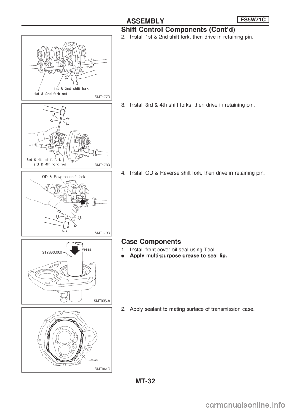
2. Install 1st & 2nd shift fork, then drive in retaining pin.
3. Install 3rd & 4th shift forks, then drive in retaining pin.
4. Install OD & Reverse shift fork, then drive in retaining pin.
Case Components
1. Install front cover oil seal using Tool.
lApply multi-purpose grease to seal lip.
2. Apply sealant to mating surface of transmission case.
SMT177D
SMT178D
SMT179D
SMT036-A
SMT061C
ASSEMBLYFS5W71C
Shift Control Components (Cont'd)
MT-32
Page 1050 of 1659
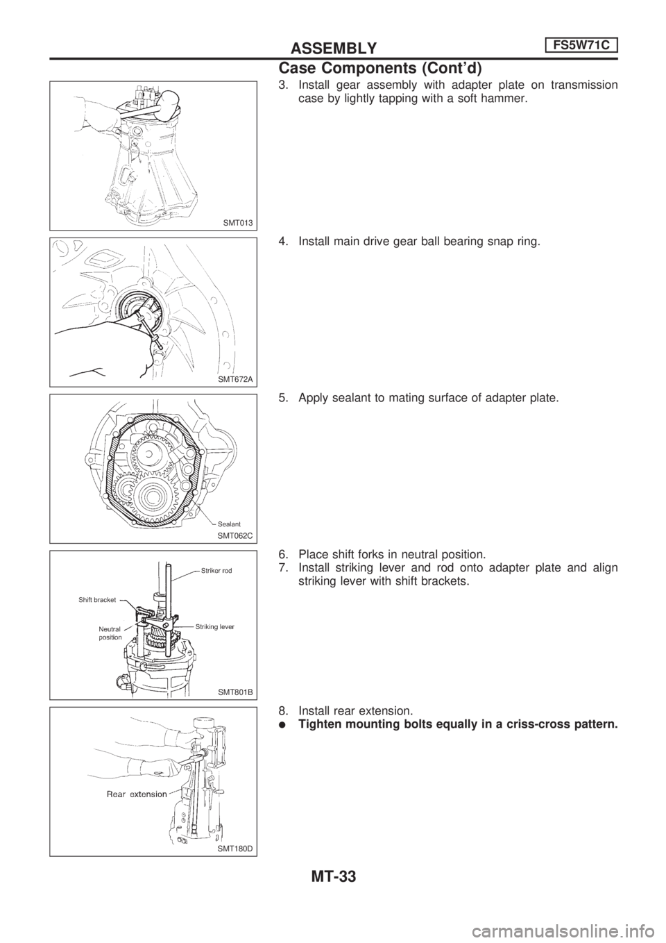
3. Install gear assembly with adapter plate on transmission
case by lightly tapping with a soft hammer.
4. Install main drive gear ball bearing snap ring.
5. Apply sealant to mating surface of adapter plate.
6. Place shift forks in neutral position.
7. Install striking lever and rod onto adapter plate and align
striking lever with shift brackets.
8. Install rear extension.
lTighten mounting bolts equally in a criss-cross pattern.
SMT013
SMT672A
SMT062C
SMT801B
SMT180D
ASSEMBLYFS5W71C
Case Components (Cont'd)
MT-33
Trending: jacking, fuse box, fuses, brake, battery location, cooling, air conditioning
