NISSAN PICK-UP 1998 Repair Manual
PICK-UP 1998
NISSAN
NISSAN
https://www.carmanualsonline.info/img/5/57374/w960_57374-0.png
NISSAN PICK-UP 1998 Repair Manual
Trending: center console, check engine, wiper fluid, rims, display, tow, open hood
Page 421 of 1659
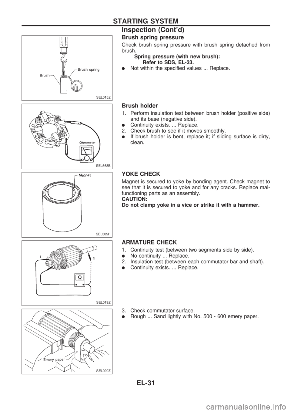
Brush spring pressure
Check brush spring pressure with brush spring detached from
brush.
Spring pressure (with new brush):
Refer to SDS, EL-33.
lNot within the specified values ... Replace.
Brush holder
1. Perform insulation test between brush holder (positive side)
and its base (negative side).
lContinuity exists. ... Replace.
2. Check brush to see if it moves smoothly.
lIf brush holder is bent, replace it; if sliding surface is dirty,
clean.
YOKE CHECK
Magnet is secured to yoke by bonding agent. Check magnet to
see that it is secured to yoke and for any cracks. Replace mal-
functioning parts as an assembly.
CAUTION:
Do not clamp yoke in a vice or strike it with a hammer.
ARMATURE CHECK
1. Continuity test (between two segments side by side).
lNo continuity ... Replace.
2. Insulation test (between each commutator bar and shaft).
lContinuity exists. ... Replace.
3. Check commutator surface.
lRough ... Sand lightly with No. 500 - 600 emery paper.
SEL015Z
SEL568B
SEL305H
SEL019Z
SEL020Z
STARTING SYSTEM
Inspection (Cont'd)
EL-31
Page 422 of 1659
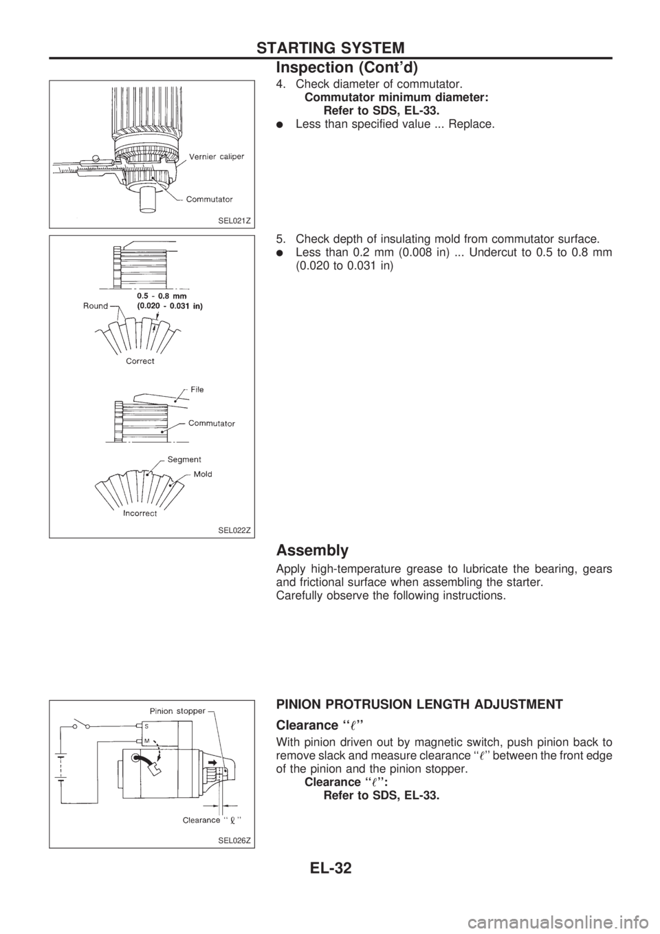
4. Check diameter of commutator.
Commutator minimum diameter:
Refer to SDS, EL-33.
lLess than specified value ... Replace.
5. Check depth of insulating mold from commutator surface.
lLess than 0.2 mm (0.008 in) ... Undercut to 0.5 to 0.8 mm
(0.020 to 0.031 in)
Assembly
Apply high-temperature grease to lubricate the bearing, gears
and frictional surface when assembling the starter.
Carefully observe the following instructions.
PINION PROTRUSION LENGTH ADJUSTMENT
Clearance ``!''
With pinion driven out by magnetic switch, push pinion back to
remove slack and measure clearance ``!'' between the front edge
of the pinion and the pinion stopper.
Clearance ``!'':
Refer to SDS, EL-33.
SEL021Z
SEL022Z
SEL026Z
STARTING SYSTEM
Inspection (Cont'd)
EL-32
Page 423 of 1659
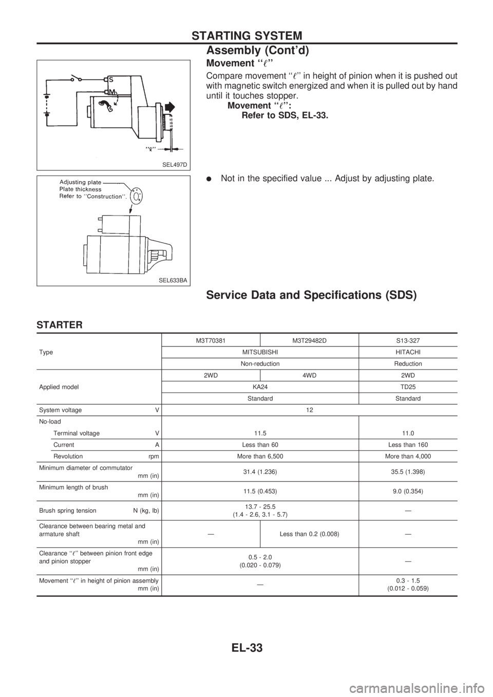
Movement ``!''
Compare movement ``!'' in height of pinion when it is pushed out
with magnetic switch energized and when it is pulled out by hand
until it touches stopper.
Movement ``!'':
Refer to SDS, EL-33.
lNot in the specified value ... Adjust by adjusting plate.
Service Data and Specifications (SDS)
STARTER
TypeM3T70381 M3T29482D S13-327
MITSUBISHI HITACHI
Non-reduction Reduction
Applied model2WD 4WD 2WD
KA24 TD25
Standard Standard
System voltage V 12
No-load
Terminal voltage V 11.5 11.0
Current A Less than 60 Less than 160
Revolution rpm More than 6,500 More than 4,000
Minimum diameter of commutator
mm (in)31.4 (1.236) 35.5 (1.398)
Minimum length of brush
mm (in)11.5 (0.453) 9.0 (0.354)
Brush spring tension N (kg, lb)13.7 - 25.5
(1.4 - 2.6, 3.1 - 5.7)Ð
Clearance between bearing metal and
armature shaft
mm (in)Ð Less than 0.2 (0.008) Ð
Clearance ``!'' between pinion front edge
and pinion stopper
mm (in)0.5 - 2.0
(0.020 - 0.079)Ð
Movement ``!'' in height of pinion assembly
mm (in)Ð0.3 - 1.5
(0.012 - 0.059)
SEL497D
SEL633BA
STARTING SYSTEM
Assembly (Cont'd)
EL-33
Page 424 of 1659
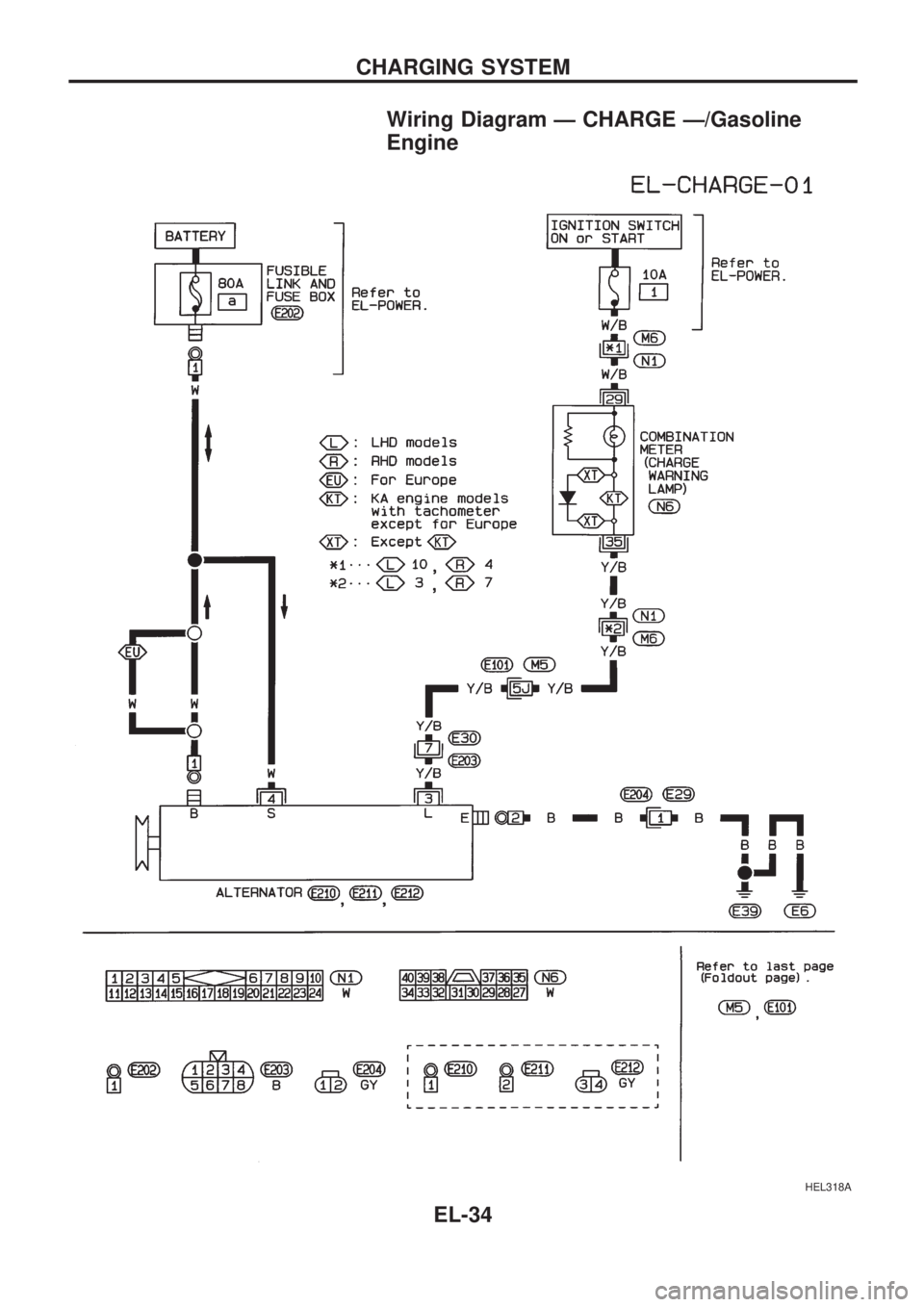
Wiring Diagram Ð CHARGE Ð/Gasoline
Engine
HEL318A
CHARGING SYSTEM
EL-34
Page 425 of 1659
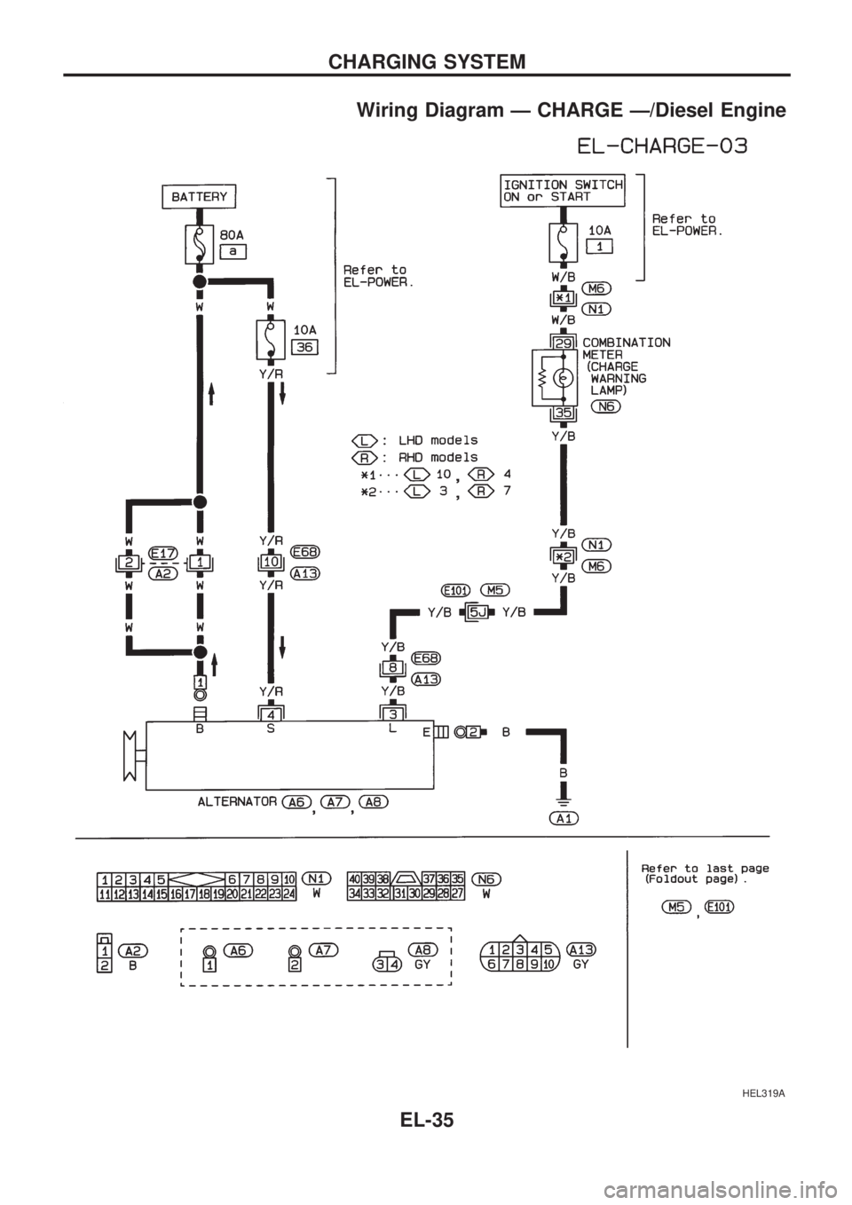
Wiring Diagram Ð CHARGE Ð/Diesel Engine
HEL319A
CHARGING SYSTEM
EL-35
Page 426 of 1659
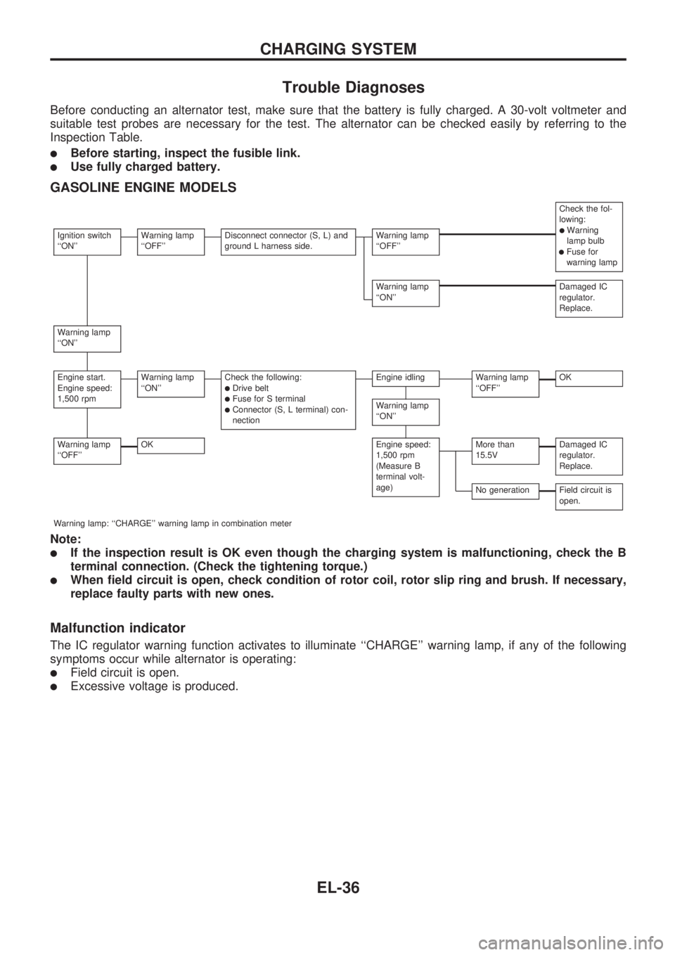
Trouble Diagnoses
Before conducting an alternator test, make sure that the battery is fully charged. A 30-volt voltmeter and
suitable test probes are necessary for the test. The alternator can be checked easily by referring to the
Inspection Table.
lBefore starting, inspect the fusible link.
lUse fully charged battery.
GASOLINE ENGINE MODELS
Check the fol-
lowing:
lWarning
lamp bulb
lFuse for
warning lamp
Ignition switch
``ON''Warning lamp
``OFF''Disconnect connector (S, L) and
ground L harness side.Warning lamp
``OFF''
Warning lamp
``ON''Damaged IC
regulator.
Replace.
Warning lamp
``ON''
Engine start.
Engine speed:
1,500 rpmWarning lamp
``ON''Check the following:lDrive beltlFuse for S terminallConnector (S, L terminal) con-
nection
Engine idlingWarning lamp
``OFF''OK
Warning lamp
``ON''
Warning lamp
``OFF''OKEngine speed:
1,500 rpm
(Measure B
terminal volt-
age)More than
15.5VDamaged IC
regulator.
Replace.
No generationField circuit is
open.
Warning lamp: ``CHARGE'' warning lamp in combination meter
Note:
lIf the inspection result is OK even though the charging system is malfunctioning, check the B
terminal connection. (Check the tightening torque.)
lWhen field circuit is open, check condition of rotor coil, rotor slip ring and brush. If necessary,
replace faulty parts with new ones.
Malfunction indicator
The IC regulator warning function activates to illuminate ``CHARGE'' warning lamp, if any of the following
symptoms occur while alternator is operating:
lField circuit is open.
lExcessive voltage is produced.
CHARGING SYSTEM
EL-36
Page 427 of 1659
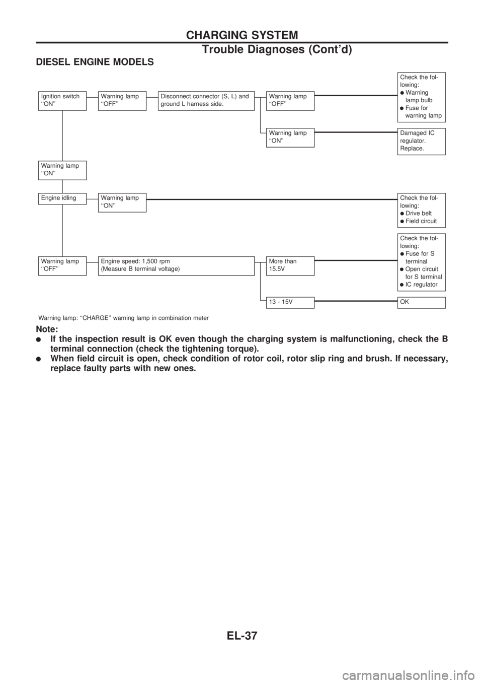
DIESEL ENGINE MODELS
Check the fol-
lowing:
lWarning
lamp bulb
lFuse for
warning lamp
Ignition switch
``ON''Warning lamp
``OFF''Disconnect connector (S, L) and
ground L harness side.Warning lamp
``OFF''
Warning lamp
``ON''Damaged IC
regulator.
Replace.
Warning lamp
``ON''
Engine idlingWarning lamp
``ON''Check the fol-
lowing:
lDrive beltlField circuit
Check the fol-
lowing:
lFuse for S
terminal
lOpen circuit
for S terminal
lIC regulator
Warning lamp
``OFF''Engine speed: 1,500 rpm
(Measure B terminal voltage)More than
15.5V
13 - 15VOK
Warning lamp: ``CHARGE'' warning lamp in combination meter
Note:
lIf the inspection result is OK even though the charging system is malfunctioning, check the B
terminal connection (check the tightening torque).
lWhen field circuit is open, check condition of rotor coil, rotor slip ring and brush. If necessary,
replace faulty parts with new ones.
CHARGING SYSTEM
Trouble Diagnoses (Cont'd)
EL-37
Page 428 of 1659
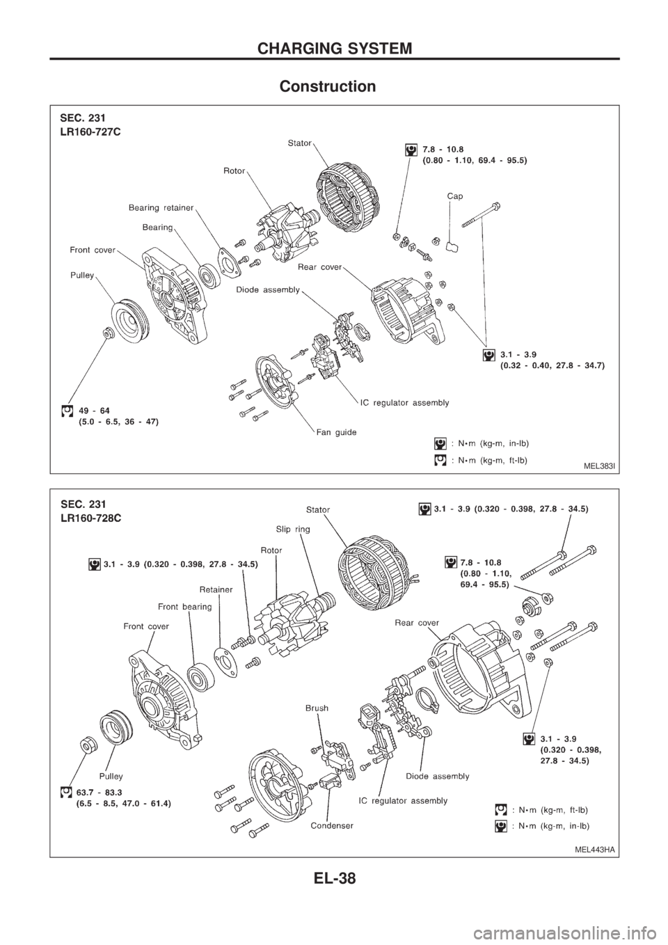
Construction
MEL383I
MEL443HA
CHARGING SYSTEM
EL-38
Page 429 of 1659
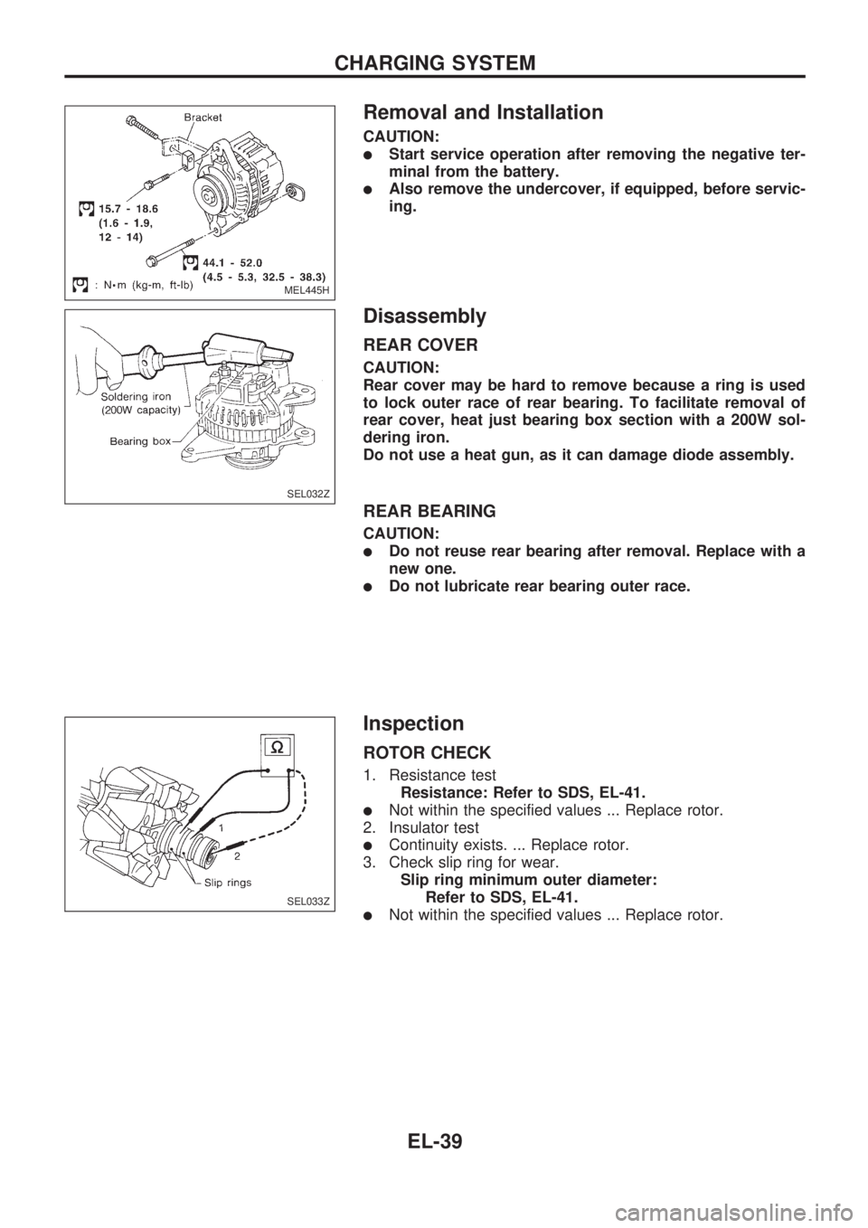
Removal and Installation
CAUTION:
lStart service operation after removing the negative ter-
minal from the battery.
lAlso remove the undercover, if equipped, before servic-
ing.
Disassembly
REAR COVER
CAUTION:
Rear cover may be hard to remove because a ring is used
to lock outer race of rear bearing. To facilitate removal of
rear cover, heat just bearing box section with a 200W sol-
dering iron.
Do not use a heat gun, as it can damage diode assembly.
REAR BEARING
CAUTION:
lDo not reuse rear bearing after removal. Replace with a
new one.
lDo not lubricate rear bearing outer race.
Inspection
ROTOR CHECK
1. Resistance test
Resistance: Refer to SDS, EL-41.
lNot within the specified values ... Replace rotor.
2. Insulator test
lContinuity exists. ... Replace rotor.
3. Check slip ring for wear.
Slip ring minimum outer diameter:
Refer to SDS, EL-41.
lNot within the specified values ... Replace rotor.
MEL445H
.
SEL032Z
SEL033Z
CHARGING SYSTEM
EL-39
Page 430 of 1659
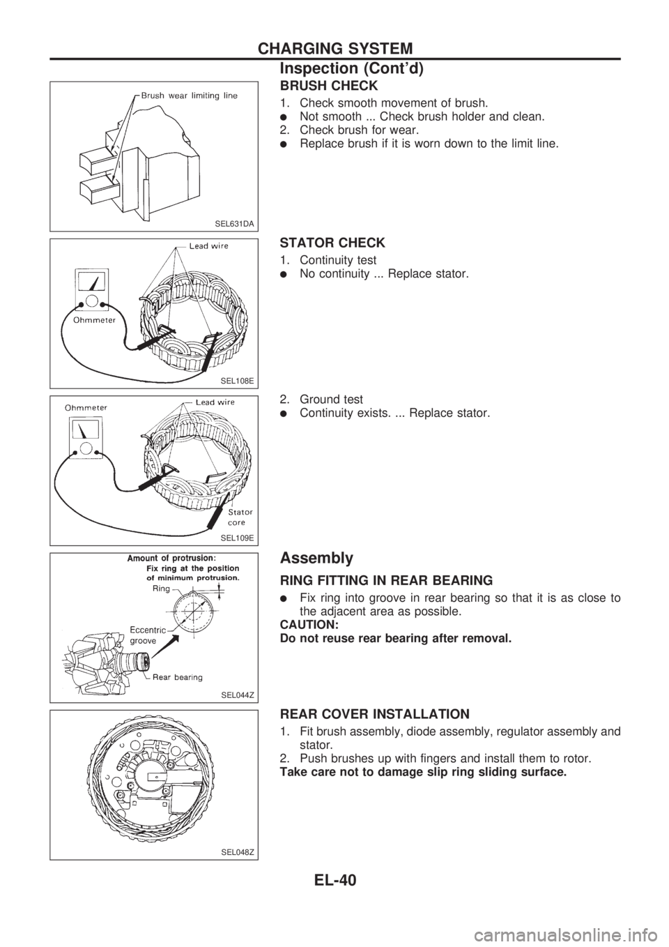
BRUSH CHECK
1. Check smooth movement of brush.
lNot smooth ... Check brush holder and clean.
2. Check brush for wear.
lReplace brush if it is worn down to the limit line.
STATOR CHECK
1. Continuity test
lNo continuity ... Replace stator.
2. Ground test
lContinuity exists. ... Replace stator.
Assembly
RING FITTING IN REAR BEARING
lFix ring into groove in rear bearing so that it is as close to
the adjacent area as possible.
CAUTION:
Do not reuse rear bearing after removal.
REAR COVER INSTALLATION
1. Fit brush assembly, diode assembly, regulator assembly and
stator.
2. Push brushes up with fingers and install them to rotor.
Take care not to damage slip ring sliding surface.
SEL631DA
SEL108E
SEL109E
SEL044Z
SEL048Z
CHARGING SYSTEM
Inspection (Cont'd)
EL-40
Trending: horn, lug pattern, wiring diagram, oil viscosity, warning lights, engine overheat, set clock

