NISSAN PRIMERA 1999 Electronic Repair Manual
Manufacturer: NISSAN, Model Year: 1999, Model line: PRIMERA, Model: NISSAN PRIMERA 1999Pages: 2267, PDF Size: 35.74 MB
Page 1641 of 2267
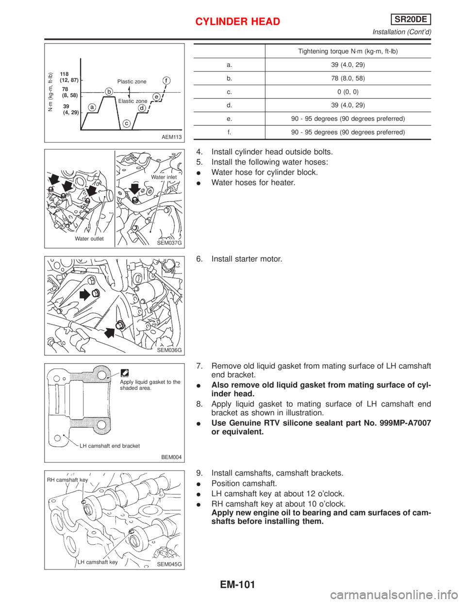
Tightening torque N×m (kg-m, ft-lb)
a. 39 (4.0, 29)
b. 78 (8.0, 58)
c. 0 (0, 0)
d. 39 (4.0, 29)
e. 90 - 95 degrees (90 degrees preferred)
f. 90 - 95 degrees (90 degrees preferred)
4. Install cylinder head outside bolts.
5. Install the following water hoses:
IWater hose for cylinder block.
IWater hoses for heater.
6. Install starter motor.
7. Remove old liquid gasket from mating surface of LH camshaft
end bracket.
IAlso remove old liquid gasket from mating surface of cyl-
inder head.
8. Apply liquid gasket to mating surface of LH camshaft end
bracket as shown in illustration.
IUse Genuine RTV silicone sealant part No. 999MP-A7007
or equivalent.
9. Install camshafts, camshaft brackets.
IPosition camshaft.
ILH camshaft key at about 12 o'clock.
IRH camshaft key at about 10 o'clock.
Apply new engine oil to bearing and cam surfaces of cam-
shafts before installing them.
AEM113
N´m (kg-m, ft-lb)
11 8
(12, 87)
78
(8, 58)
39
(4, 29)Plastic zone
Elastic zone
SEM037G Water outletWater inlet
SEM036G
BEM004 Apply liquid gasket to the
shaded area.
LH camshaft end bracket
SEM045G RH camshaft key
LH camshaft key
CYLINDER HEADSR20DE
Installation (Cont'd)
EM-101
Page 1642 of 2267
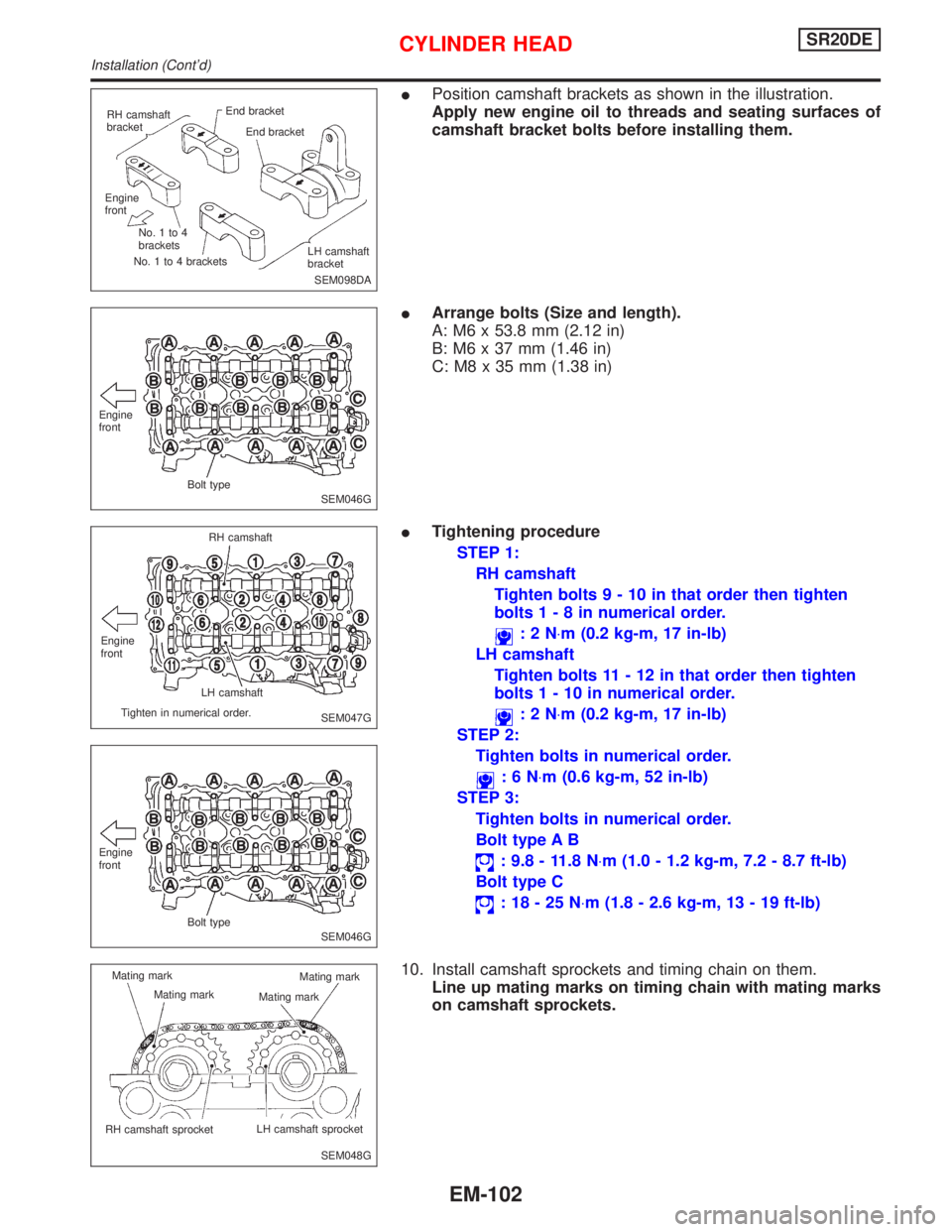
IPosition camshaft brackets as shown in the illustration.
Apply new engine oil to threads and seating surfaces of
camshaft bracket bolts before installing them.
IArrange bolts (Size and length).
A: M6 x 53.8 mm (2.12 in)
B: M6 x 37 mm (1.46 in)
C: M8 x 35 mm (1.38 in)
ITightening procedure
STEP 1:
RH camshaft
Tighten bolts9-10inthat order then tighten
bolts1-8innumerical order.
:2N×m (0.2 kg-m, 17 in-lb)
LH camshaft
Tighten bolts 11 - 12 in that order then tighten
bolts1-10innumerical order.
:2N×m (0.2 kg-m, 17 in-lb)
STEP 2:
Tighten bolts in numerical order.
:6N×m (0.6 kg-m, 52 in-lb)
STEP 3:
Tighten bolts in numerical order.
Bolt type A B
: 9.8 - 11.8 N×m (1.0 - 1.2 kg-m, 7.2 - 8.7 ft-lb)
Bolt type C
:18-25N×m (1.8 - 2.6 kg-m, 13 - 19 ft-lb)
10. Install camshaft sprockets and timing chain on them.
Line up mating marks on timing chain with mating marks
on camshaft sprockets.
SEM098DA RH camshaft
bracketEnd bracket
End bracket
Engine
front
No.1to4
brackets
No. 1 to 4 bracketsLH camshaft
bracket
SEM046G Engine
front
Bolt type
SEM047G Engine
frontRH camshaft
LH camshaft
Tighten in numerical order.
SEM046G Engine
front
Bolt type
SEM048G Mating mark
Mating mark
.RH camshaft sprocket.LH camshaft sprocket Mating mark
Mating mark
CYLINDER HEADSR20DE
Installation (Cont'd)
EM-102
Page 1643 of 2267
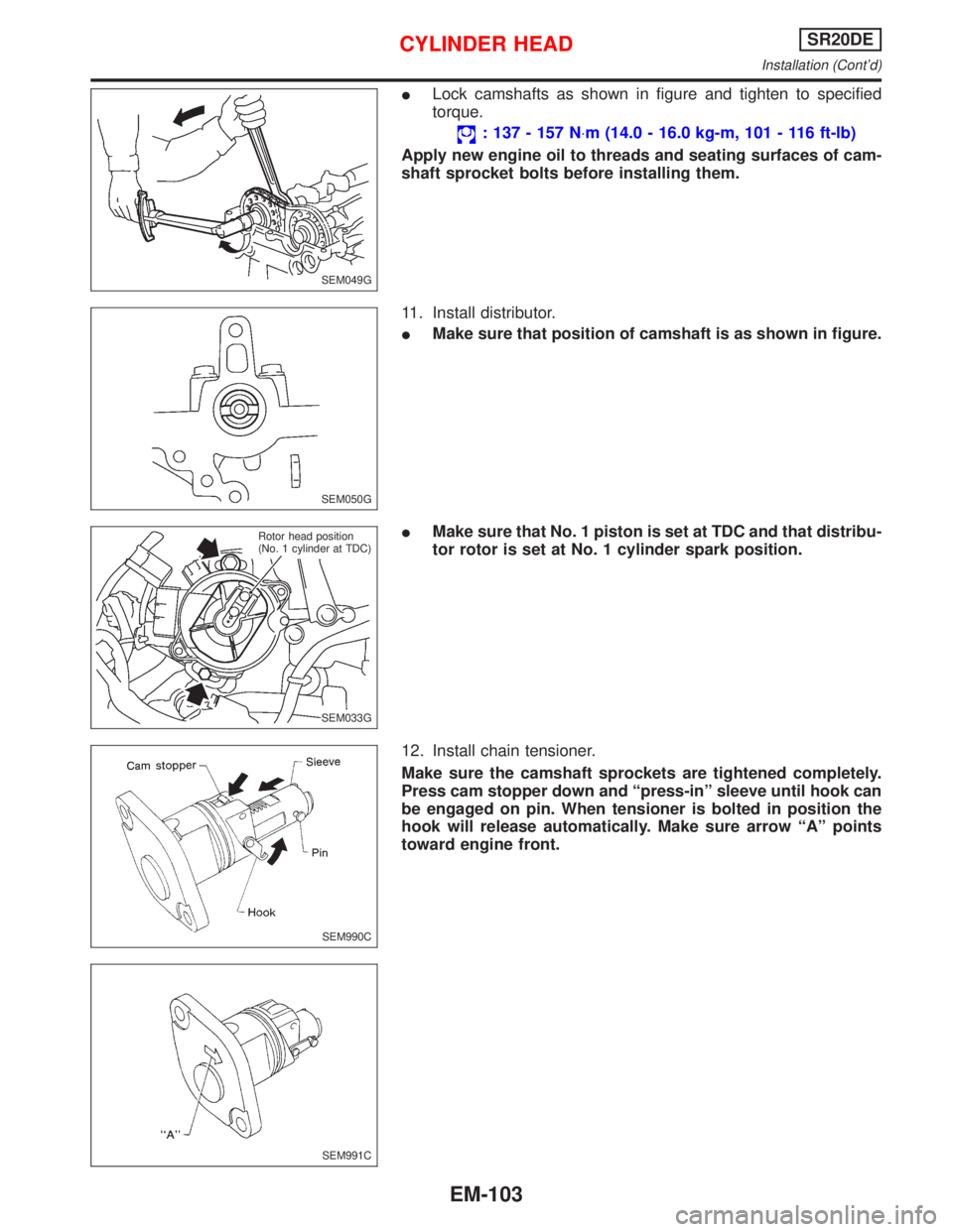
ILock camshafts as shown in figure and tighten to specified
torque.
: 137 - 157 N×m (14.0 - 16.0 kg-m, 101 - 116 ft-lb)
Apply new engine oil to threads and seating surfaces of cam-
shaft sprocket bolts before installing them.
11. Install distributor.
IMake sure that position of camshaft is as shown in figure.
IMake sure that No. 1 piston is set at TDC and that distribu-
tor rotor is set at No. 1 cylinder spark position.
12. Install chain tensioner.
Make sure the camshaft sprockets are tightened completely.
Press cam stopper down and ªpress-inº sleeve until hook can
be engaged on pin. When tensioner is bolted in position the
hook will release automatically. Make sure arrow ªAº points
toward engine front.
SEM049G
SEM050G
SEM033G Rotor head position
(No. 1 cylinder at TDC)
SEM990C
SEM991C
CYLINDER HEADSR20DE
Installation (Cont'd)
EM-103
Page 1644 of 2267
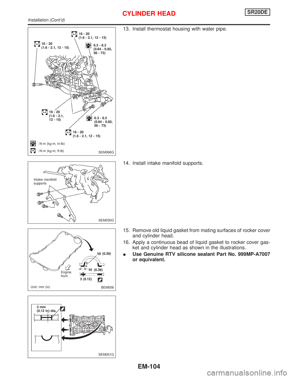
13. Install thermostat housing with water pipe.
14. Install intake manifold supports.
15. Remove old liquid gasket from mating surfaces of rocker cover
and cylinder head.
16. Apply a continuous bead of liquid gasket to rocker cover gas-
ket and cylinder head as shown in the illustrations.
IUse Genuine RTV silicone sealant Part No. 999MP-A7007
or equivalent.
SEM066G
16-20
(1.6 - 2.1, 12 - 15)
6.3 - 8.3
(0.64 - 0.85,
56 - 73)16-20
(1.6 - 2.1, 12 - 15)
16-20
(1.6 - 2.1,
12 - 15)
16-20
(1.6 - 2.1, 12 - 15)
6.3 - 8.3
(0.64 - 0.85,
56 - 73)
N´m (kg-m, in-lb)
N´m (kg-m, ft-lb)
SEM030G Intake manifold
supports
BEM006 Engine
front
Unit: mm (in)3 (0.12)(0.39)
(0.39)
SEM051G 3mm
(0.12 in) dia.
CYLINDER HEADSR20DE
Installation (Cont'd)
EM-104
Page 1645 of 2267
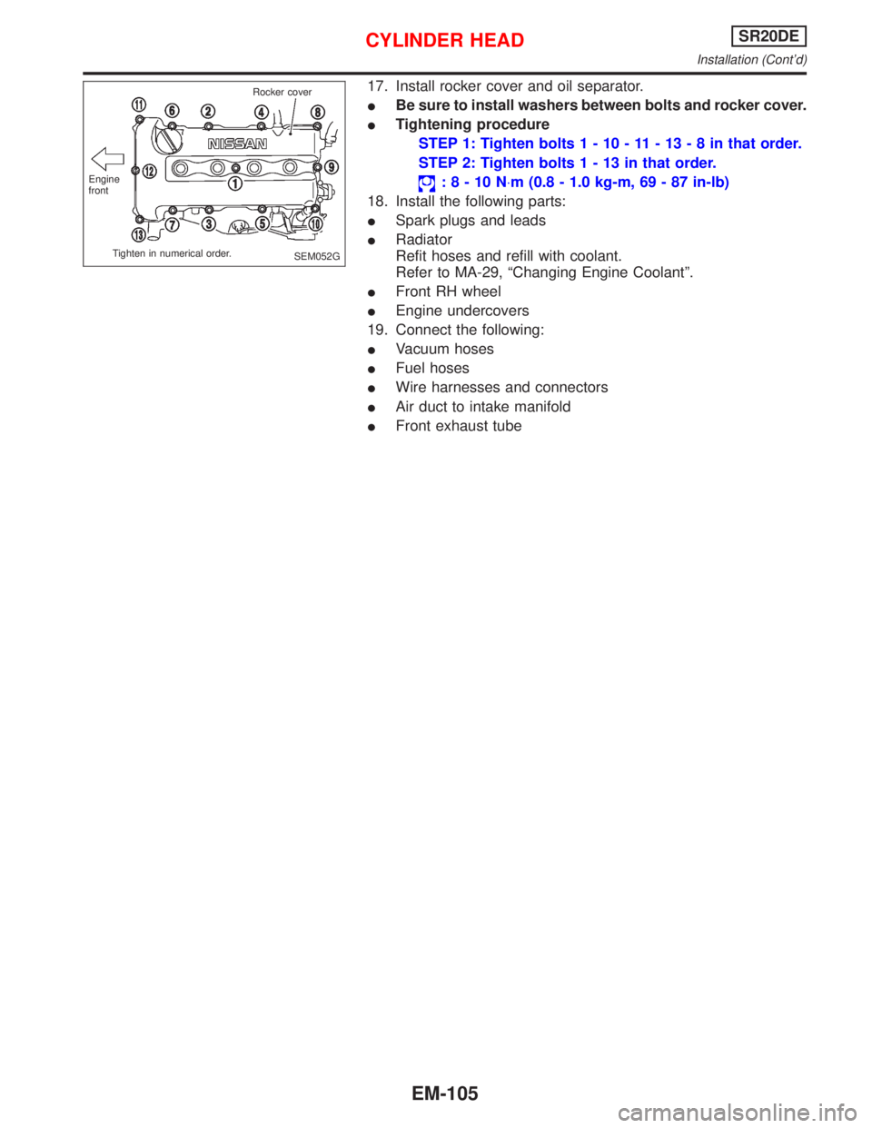
17. Install rocker cover and oil separator.
IBe sure to install washers between bolts and rocker cover.
ITightening procedure
STEP 1: Tighten bolts1-10-11-13-8inthat order.
STEP 2: Tighten bolts1-13inthat order.
:8-10N×m (0.8 - 1.0 kg-m, 69 - 87 in-lb)
18. Install the following parts:
ISpark plugs and leads
IRadiator
Refit hoses and refill with coolant.
Refer to MA-29, ªChanging Engine Coolantº.
IFront RH wheel
IEngine undercovers
19. Connect the following:
IVacuum hoses
IFuel hoses
IWire harnesses and connectors
IAir duct to intake manifold
IFront exhaust tube
SEM052G Engine
front
Tighten in numerical order.Rocker cover
CYLINDER HEADSR20DE
Installation (Cont'd)
EM-105
Page 1646 of 2267
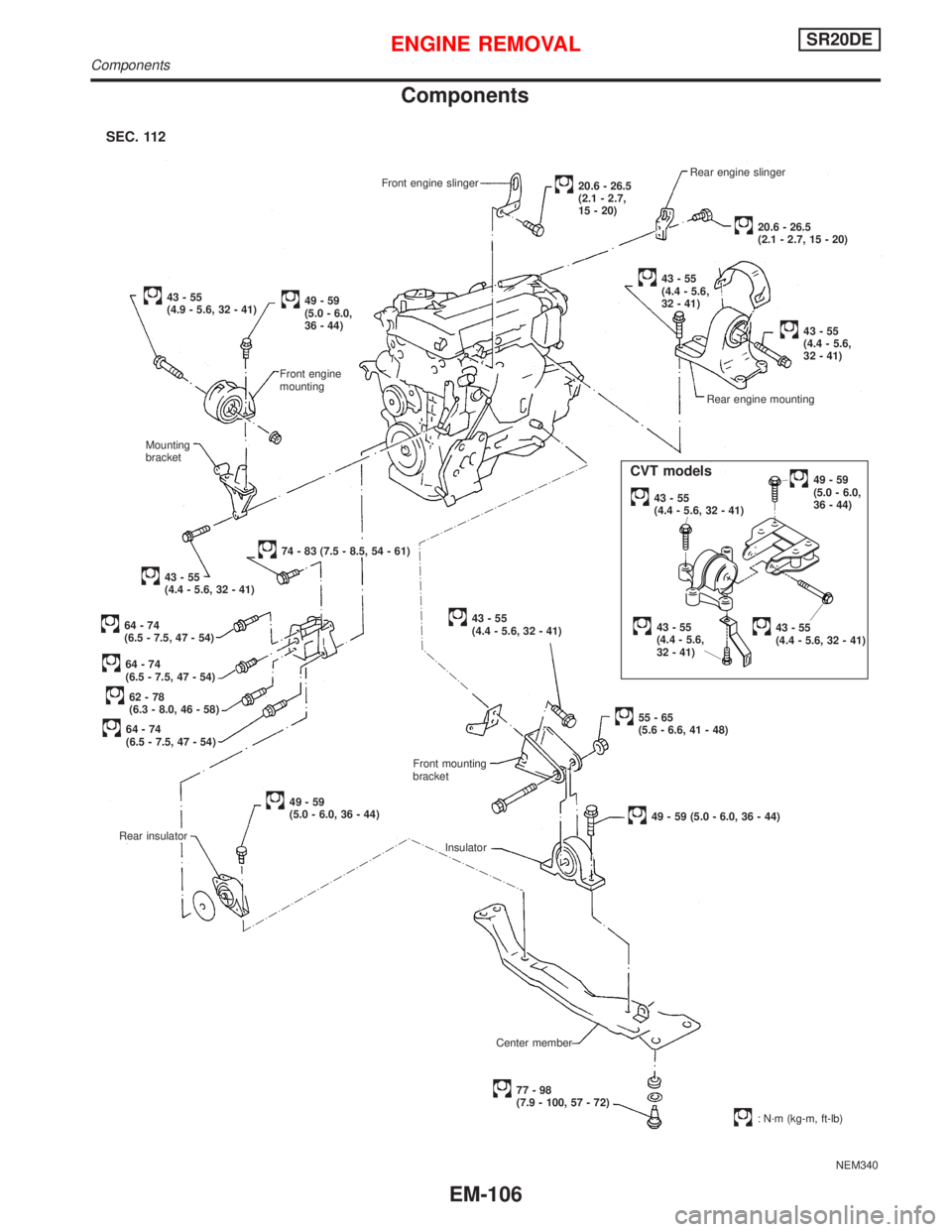
Components
NEM340 Front engine slinger
Rear insulator
49-59
(5.0 - 6.0, 36 - 44)Rear engine mounting
43-55
(4.4 - 5.6,
32 - 41)
43-55
(4.4 - 5.6,
32 - 41)Rear engine slinger
20.6 - 26.5
(2.1 - 2.7, 15 - 20)
20.6 - 26.5
(2.1 - 2.7,
15 - 20)
43-55
(4.4 - 5.6,
32 - 41)
55-65
(5.6 - 6.6, 41 - 48)
49 - 59 (5.0 - 6.0, 36 - 44) Front mounting
bracket
Insulator
Center member
77-98
(7.9 - 100, 57 - 72)
: N´m (kg-m, ft-lb)
.43-55
(4.4 - 5.6, 32 - 41)
.49-59
(5.0 - 6.0,
36 - 44)
43-55
(4.4 - 5.6, 32 - 41)
43-55
(4.9 - 5.6, 32 - 41)49-59
(5.0 - 6.0,
36 - 44)
Front engine
mounting
Mounting
bracket
74 - 83 (7.5 - 8.5, 54 - 61)
43-55
(4.4 - 5.6, 32 - 41)
64-74
(6.5 - 7.5, 47 - 54)
64-74
(6.5 - 7.5, 47 - 54)
62-78
(6.3 - 8.0, 46 - 58)
64-74
(6.5 - 7.5, 47 - 54)
SEC. 112
.43-55
(4.4 - 5.6, 32 - 41)
CVT models
ENGINE REMOVALSR20DE
Components
EM-106
Page 1647 of 2267
WARNING:
IPosition vehicle on a flat and solid surface.
IPlace chocks at front and back of rear wheels.
IDo not remove engine until exhaust system has com-
pletely cooled;
Otherwise, you may burn yourself and/or fire may break
out in fuel line.
IBefore disconnecting fuel hose, release fuel pressure
from fuel line.
Refer to ªReleasing Fuel Pressureº in EC section.
IBe sure to hoist engine and transaxle in a safe manner.
IFor engines not equipped with engine slingers, attach
slingers and bolts described in PARTS CATALOG.
CAUTION:
IWhen lifting engine, be sure to clear surrounding parts.
Use special care for accelerator cable, brake lines and
brake master cylinder.
IIn hoisting the engine, always use engine slingers in a
safe manner.
IWhen removing drive shaft, be careful not to damage
grease seal of transaxle.
Removal
1. Remove engine under cover and hood.
2. Drain coolant from both cylinder block, and radiator.
3. Drain engine oil.
4. Remove vacuum hoses, fuel hoses, wires, harness and con-
nectors.
5. Remove exhaust tubes, ball joints and drive shafts.
6. Remove radiator and fans.
7. Remove drive belts.
8. Remove alternator, compressor and power steering oil pump
from engine.
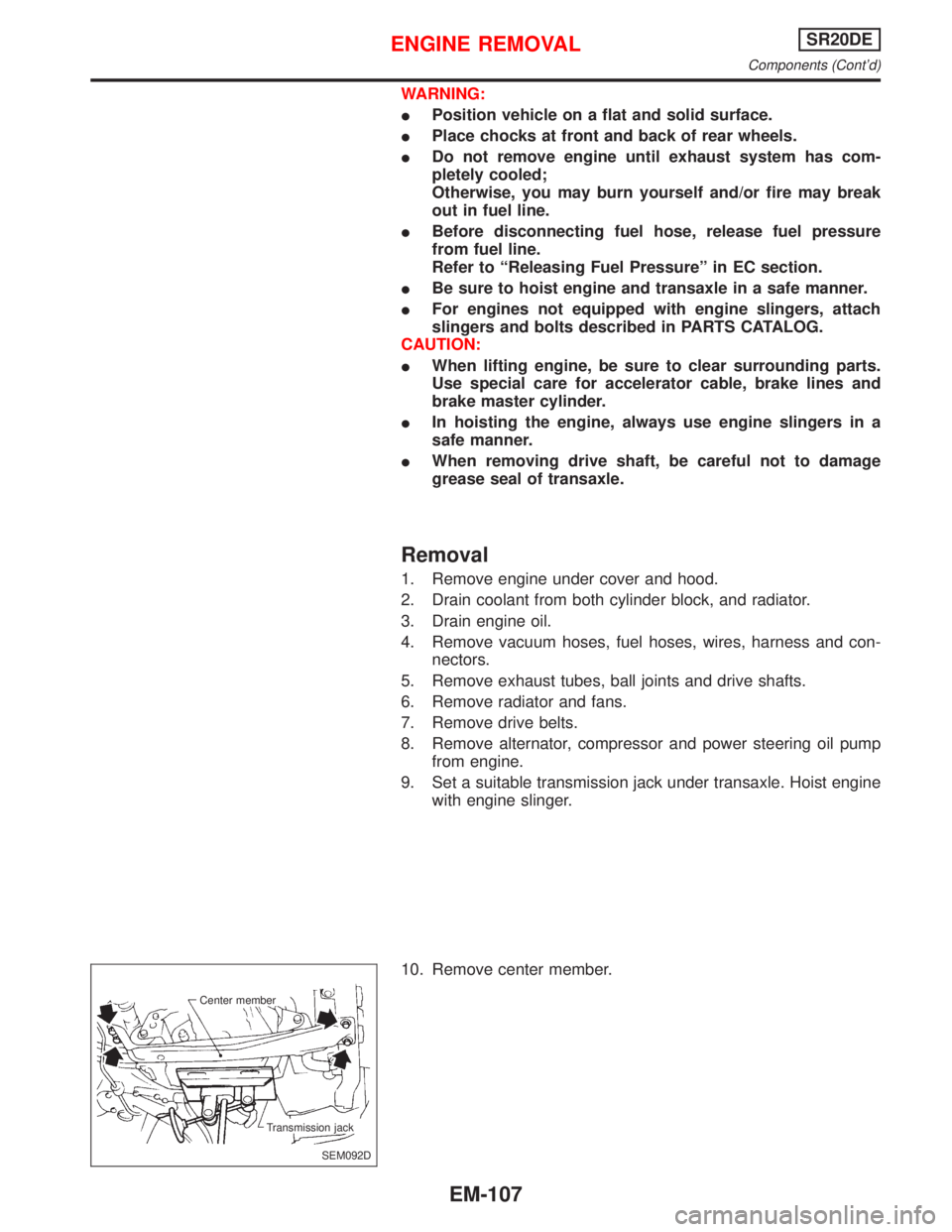
9. Set a suitable transmission jack under transaxle. Hoist engine
with engine slinger.
10. Remove center member.
SEM092D Center member
Transmission jack
ENGINE REMOVALSR20DE
Components (Cont'd)
EM-107
Page 1648 of 2267
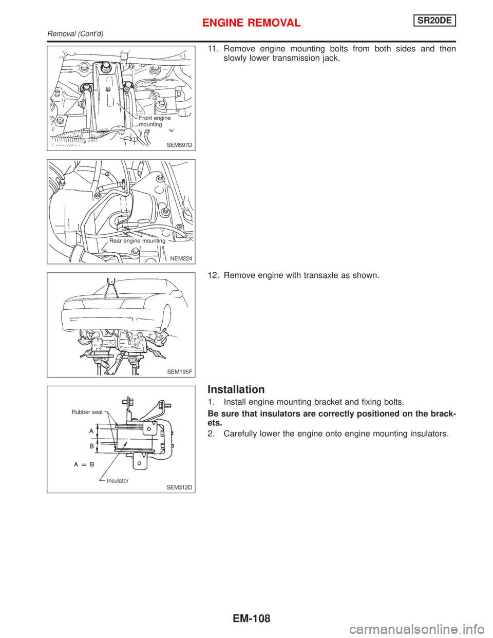
11. Remove engine mounting bolts from both sides and then
slowly lower transmission jack.
12. Remove engine with transaxle as shown.
Installation
1. Install engine mounting bracket and fixing bolts.
Be sure that insulators are correctly positioned on the brack-
ets.
2. Carefully lower the engine onto engine mounting insulators.
SEM597D Front engine
mounting
NEM224
.Rear engine mounting
SEM195F
SEM312D Insulator Rubber seat
ENGINE REMOVALSR20DE
Removal (Cont'd)
EM-108
Page 1649 of 2267
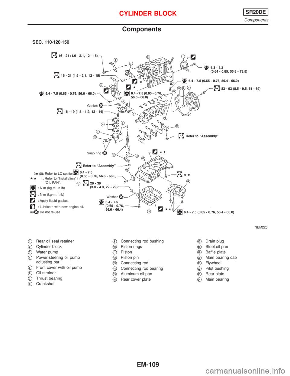
Components
p1Rear oil seal retainer
p2Cylinder block
p3Water pump
p4Power steering oil pump
adjusting bar
p5Front cover with oil pump
p6Oil strainer
p7Thrust bearing
p8Crankshaft
p9Connecting rod bushing
p10Piston rings
p11Piston
p12Piston pin
p13Connecting rod
p14Connecting rod bearing
p15Aluminum oil pan
p16Rear cover plate
p17Drain plug
p18Steel oil pan
p19Baffle plate
p20Main bearing cap
p21Flywheel
p22Pilot bushing
p23Rear plate
p24Main bearing
NEM225
p4p3
p2p1
6.3 - 8.3
(0.64 - 0.85, 55.8 - 73.5)
16 - 21 (1.6 - 2.1, 12 - 15)
p5
16 - 21 (1.6 - 2.1, 12 - 15)
6.4 - 7.5 (0.65 - 0.76, 56.6 - 66.0)
Gasket
p6
.6.4 - 7.5 (0.65 - 0.76,
56.6 - 66.0)
16 - 19 (1.6 - 1.9, 12 - 14)
p2383 - 93 (8.5 - 9.5, 61 - 69)
p10p9
p8
p22
p11
p12
Snap ringp14
Refer to ªAssemblyº
Refer to ªAssemblyº
p166.4 - 7.5
(0.65 - 0.76, 56.6 - 66.0)
p1729-39
(3.0 - 4.0, 22 - 29)
6.4 - 7.5
(0.65 - 0.76,
56.6 - 66.4) îHîî: Refer to LC section.
HH: Refer to ªInstallationº in
ªOIL PANº.
: N´m (kg-m, in-lb)
: N´m (kg-m, ft-lb)
: Apply liquid gasket.
: Lubricate with new engine oil.
îî
: Do not re-useHH
p24
Washer
p21
p20
HH
p19
6.4 - 7.5 (0.65 - 0.76, 56.4 - 66.0)
p13HH
p7
6.4 - 7.5 (0.65 - 0.76, 56.4 - 66.0).H
H
SEC. 110×120×150
p15
p18
CYLINDER BLOCKSR20DE
Components
EM-109
Page 1650 of 2267
CAUTION:
IWhen installing sliding parts (bearings, pistons, etc.),
apply new engine oil to the sliding surfaces.
IPlace removed parts such as bearings and bearing caps
in their correct order and direction.
IWhen installing connecting rod nuts and main bearing cap
bolts, apply new engine oil to threads and seating sur-
faces.
IDo not allow any magnetic materials to contact the ring
gear teeth of flywheel/drive plate.
Disassembly
PISTON AND CRANKSHAFT
1. Place engine on a work stand.
2. Remove cylinder head.
Refer to ªRemovalº in ªCYLINDER HEADº (EM-87).
3. Remove oil pan.
Refer to ªRemovalº in ªOIL PANº (EM-70).
4. Remove timing chain.
Refer to ªRemovalº in ªTIMING CHAINº (EM-76).
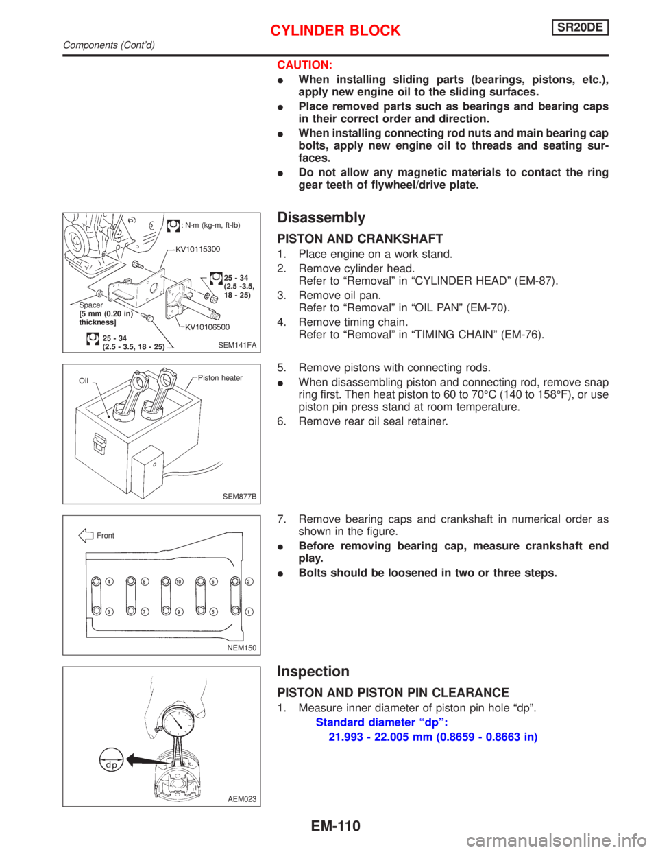
5. Remove pistons with connecting rods.
IWhen disassembling piston and connecting rod, remove snap
ring first. Then heat piston to 60 to 70ÉC (140 to 158ÉF), or use
piston pin press stand at room temperature.
6. Remove rear oil seal retainer.
7. Remove bearing caps and crankshaft in numerical order as
shown in the figure.
IBefore removing bearing cap, measure crankshaft end
play.
IBolts should be loosened in two or three steps.
Inspection
PISTON AND PISTON PIN CLEARANCE
1. Measure inner diameter of piston pin hole ªdpº.
Standard diameter ªdpº:
21.993 - 22.005 mm (0.8659 - 0.8663 in)
SEM141FA
: N´m (kg-m, ft-lb)
25-34
(2.5 -3.5,
18 - 25)
Spacer
[5 mm (0.20 in)
thickness]
25-34
(2.5 - 3.5, 18 - 25)
SEM877B Piston heater
Oil
NEM150 Front
p2
p1
p4
p3
p8
p7
p10
p9
p6
p5
AEM023
CYLINDER BLOCKSR20DE
Components (Cont'd)
EM-110