NISSAN PULSAR 1987 Workshop Manual
Manufacturer: NISSAN, Model Year: 1987, Model line: PULSAR, Model: NISSAN PULSAR 1987Pages: 238, PDF Size: 28.91 MB
Page 101 of 238
Fuel and Engine Management 101
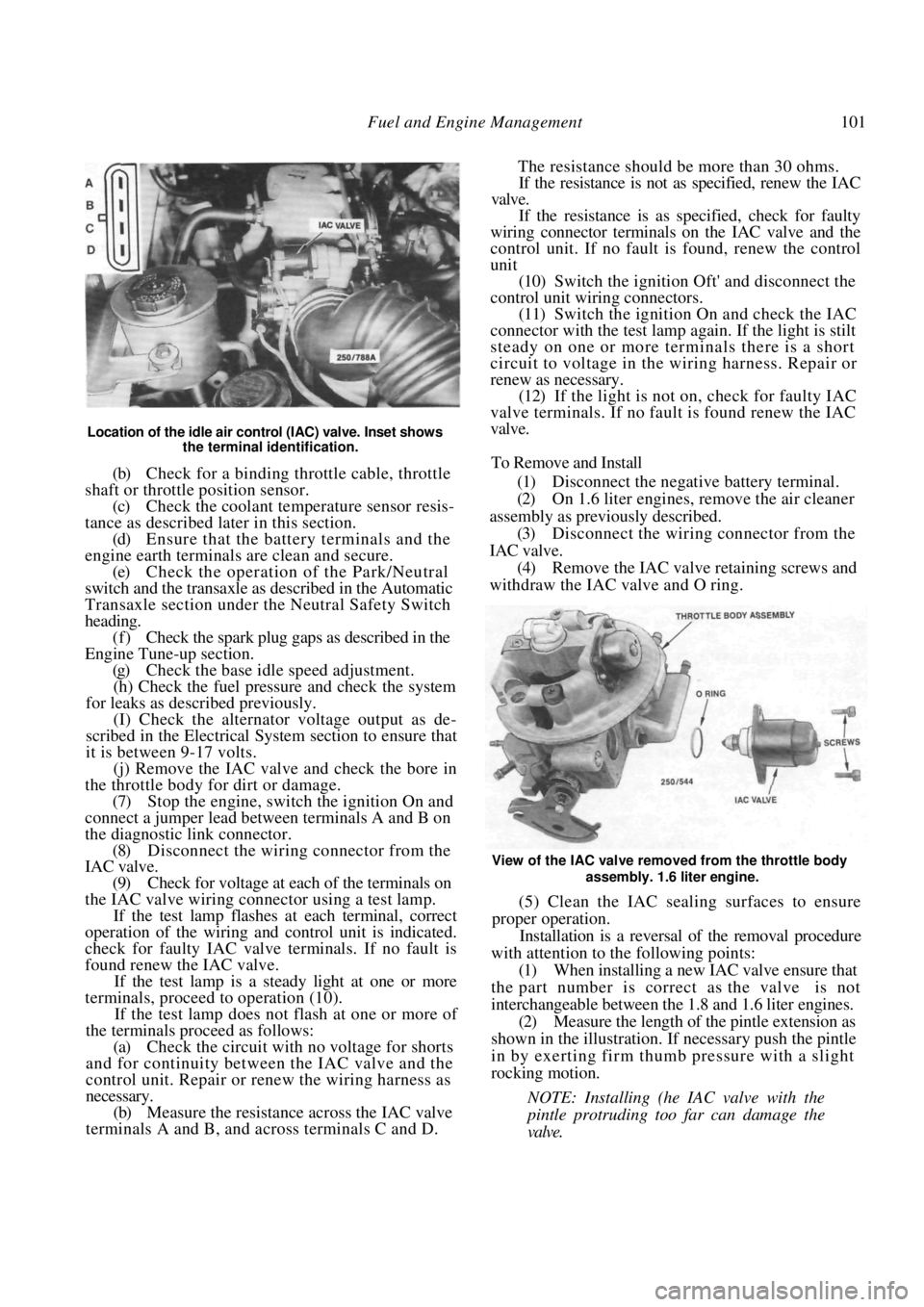
Location of the idle air control (IAC) valve. Inset shows the terminal identification.
(b) Check for a binding throttle cable, throttle
shaft or throttle position sensor. (c) Check the coolant temperature sensor resis-
tance as described later in this section. (d) Ensure that the battery terminals and the
engine earth terminals are clean and secure.
(e) Check the operation of the Park/Neutral
switch and the transaxle as described in the Automatic
Transaxle section under the Neutral Safety Switch
heading. (f) Check the spark plug gaps as described in the
Engine Tune-up section.
(g) Check the base idle speed adjustment.
(h) Check the fuel pressure and check the system
for leaks as described previously.
(I) Check the alternator voltage output as de-
scribed in the Electrical System section to ensure that
it is between 9-17 volts.
(j) Remove the IAC valve and check the bore in
the throttle body for dirt or damage.
(7) Stop the engine, switch the ignition On and
connect a jumper lead between terminals A and B on
the diagnostic link connector. (8) Disconnect the wiring connector from the
IAC valve.
(9) Check for voltage at each of the terminals on
the IAC valve wiring connector using a test lamp. If the test lamp flashes at each terminal, correct
operation of the wiring and control unit is indicated.
check for faulty IAC valve terminals. If no fault is
found renew the IAC valve.
If the test lamp is a steady light at one or more
terminals, proceed to operation (10).
If the test lamp does not flash at one or more of
the terminals proceed as follows:
(a) Check the circuit with no voltage for shorts
and for continuity between the IAC valve and the
control unit. Repair or renew the wiring harness as
necessary.
(b) Measure the resistance across the IAC valve
terminals A and B, and across terminals C and D. The resistance should be more than 30 ohms.
If the resistance is not as specified, renew the IAC
valve.
If the resistance is as specified, check for faulty
wiring connector terminals on the IAC valve and the
control unit. If no fault is found, renew the control
unit
(10) Switch the ignition Oft' and disconnect the
control unit wiring connectors. (11) Switch the ignition On and check the IAC
connector with the test lamp again. If the light is stilt
steady on one or more terminals there is a short
circuit to voltage in the wiring harness. Repair or
renew as necessary. (12) If the light is not on, check for faulty IAC
valve terminals. If no fault is found renew the IAC
valve.
To Remove and Install
(1) Disconnect the negative battery terminal.
(2) On 1.6 liter engines, remove the air cleaner
assembly as previously described. (3) Disconnect the wiring connector from the
IAC valve. (4) Remove the IAC valve retaining screws and
withdraw the IAC valve and O ring.
View of the IAC valve removed from the throttle body
assembly. 1.6 liter engine.
(5) Clean the IAC sealing surfaces to ensure
proper operation.
Installation is a reversal of the removal procedure
with attention to the following points:
(1) When installing a new IAC valve ensure that
the part number is correct as the valve is not
interchangeable between the 1.8 and 1.6 liter engines.
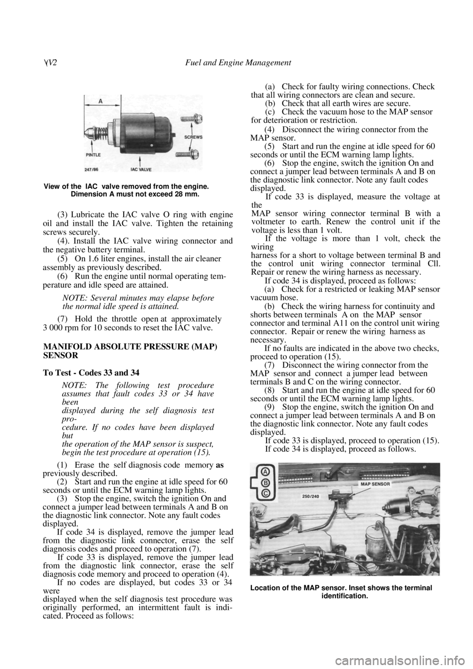
(2) Measure the length of the pintle extension as
shown in the illustration. If necessary push the pintle
in by exerting firm thum b pressure with a slight
rocking motion.
NOTE: Installing (he IAC valve with the
pintle protruding too far can damage the
valve.
Page 102 of 238
\(V2 Fuel and Engine Management
View of the IAC valve removed from the engine. Dimension A must not exceed 28 mm.
(3) Lubricate the IAC valve O ring with engine
oil and install the IAC valve. Tighten the retaining
screws securely.
(4). Install the IAC valve wiring connector and
the negative battery terminal.
(5) On 1.6 liter engines, install the air cleaner
assembly as previously described. (6) Run the engine until normal operating tem-
perature and idle speed are attained.
NOTE: Several minutes may elapse before
the normal idle speed is attained.
(7) Hold the throttle open at approximately
3 000 rpm for 10 seconds to reset the IAC valve.
MANIFOLD ABSOLUTE PRESSURE (MAP)
SENSOR
To Test - Codes 33 and 34
NOTE: The following test procedure
assumes that fault codes 33 or 34 have
been
displayed during the self diagnosis test
pro-
cedure. If no codes have been displayed
but
the operation of the MAP sensor is suspect,
begin the test procedure at operation (15).
(1) Erase the self diagnosis code memory as
previously described.
(2) Start and run the engine at idle speed for 60
seconds or until the ECM warning lamp lights.
(3) Stop the engine, switch the ignition On and
connect a jumper lead between terminals A and B on
the diagnostic link connector. Note any fault codes
displayed. If code 34 is displayed, remove the jumper lead
from the diagnostic link connector, erase the self
diagnosis codes and proceed to operation (7).
If code 33 is displayed, remove the jumper lead
from the diagnostic link connector, erase the self
diagnosis code memory and proceed to operation (4).
If no codes are displayed, but codes 33 or 34
were
displayed when the self diagnosis test procedure was
originally performed, an intermittent fault is indi-
cated. Proceed as follows:
(a) Check for faulty wiring connections. Check
that all wiring connectors are clean and secure. (b) Check that all earth wires are secure.
(c) Check the vacuum hose to the MAP sensor
for deterioration or restriction.
(4) Disconnect the wiring connector from the
MAP sensor. (5) Start and run the engine at idle speed for 60
seconds or until the ECM warning lamp lights. (6) Stop the engine, switch the ignition On and
connect a jumper lead between terminals A and B on
the diagnostic link connector. Note any fault codes
displayed.
If code 33 is displayed, measure the voltage at
the
MAP sensor wiring connector terminal B with a
voltmeter to earth. Renew the control unit if the
voltage is less than 1 volt.
If the voltage is more than 1 volt, check the
wiring
harness for a short to voltage between terminal B and
the control unit wiring connector terminal Cll.
Repair or renew the wiring harness as necessary.
If code 34 is displayed, proceed as follows:
(a) Check for a restricted or leaking MAP sensor
vacuum hose.
(b) Check the wiring harness for continuity and
shorts between terminals A on the MAP sensor
connector and terminal A11 on the control unit wiring
connector. Repair or renew the wiring harness as
necessary.
If no faults are indicated in the above two checks,
proceed to operation (15).
(7) Disconnect the wiring connector from the
MAP sensor and connect a jumper lead between
terminals B and C on the wiring connector. (8) Start and run the engine at idle speed for 60
seconds or until the ECM warning lamp lights. (9) Stop the engine, switch the ignition On and
connect a jumper lead between terminals A and B on
the diagnostic link connector. Note any fault codes
displayed.
If code 33 is displayed, proceed to operation (15).
If code 34 is displayed, proceed as follows.
Location of the MAP sensor. Inset shows the terminal
identification.
Page 103 of 238
Fuel and Engine Management 103
(10) Remove the jumper lead from the MAP
sensor wiring connector and measure the voltage
across terminals A and C on the MAP sensor wiring
connector.
If the voltage is below 4 volts, proceed to opera-
tion (12).
If the voltage is 4-6 volts, proceed as follows.
(11) With the ignition switched Off, disconnect
the wiring connectors from the control unit and check
the wiring harness for contin uity and shorts between
MAP sensor wiring connector terminal B and control
unit wiring connector terminal C11. Check the wiring
connectors for faults. Repair or renew the wiring
harness as necessary.
If no fault is found, renew the control unit and
retest for fault codes.
(12) Disconnect the wiring connector from the
throttle position sensor. (13) Measure the voltage across terminals A and
C on the MAP sensor wiring connector.
If the voltage is 4-6 volts, renew the throttle
position sensor as describe d later in this section.
If the voltage is below 4 volts, proceed as follows.
(14) With the ignition switched Off, disconnect
the wiring connectors from the control unit and check
the wiring harness for contin uity and shorts between
the MAP sensor wiring connector terminal C and
control unit wiring connector terminal C14. Check the
wiring connectors. Repair or renew the wiring harness
as necessary.
If no fault is found, renew the control unit and
retest for fault codes.
(15) Test the MAP sensor as follows:
(a) With the ignition switched On and the MAP
sensor wiring connector connected, measure the volt-
age across terminals A an d B by backprobing the
MAP sensor wiring connector. The voltage should be
as follows:
ALTITUDE VOLTAGE
Below 305 m .......................................... 3.8-5.5 volts
305-610 m ............................................. 3.6-5.3 volts
610-914 m ............................................. 3.5-5.1 volts
914-1 219 m .......................................... 3.3-5.0 volts
1 219-1 524 m ...................................... 3.2-4.8 volts
1 524-1 829 m ...................................... 3.0-4.6 volts
1 829-2 133 m ...................................... 2.9-4.5 volts
2 133-2 438 m ....................................... 2.8-4.3 volts
2 438-2 743 m ...................................... 2.6-4.2 volts
2 743-3 048 m ...................................... 2.5-4.0 volts
If the voltage is not as specified, renew the MAP
sensor.
(b) If the voltage is as specified, apply a 34 kPa
vacuum to the MAP sensor using a vacuum pump.
The voltage should be 1.2-2.3 volts lower than that
measured in operation (a).
If the voltage is not as specified, renew the MAP
sensor.
If no fault is found, check the vacuum supply hose
for restriction, leakage or correct installation.
To Remove and Install
(1) Disconnect the negative battery terminal.
(2) Disconnect the MAP sensor wiring connec-
tor and the vacuum hose. (3) Remove the retaining sc rews and remove the
MAP sensor from the vehicle.
Installation is a reversal of the removal procedure
with attention to the following points:
(1) If a new MAP sensor is to be installed ensure
that the colored insert inside the connector cavity
matches the color of the wiring connector.
(2) Ensure that the wiri ng connector and the
vacuum hose are connected securely.
THROTTLE CABLE
To Remove and Install
(1) On 1.6 liter engines, remove the air cleaner
assembly as previously described.
(2) Slide the outer throttle cable from the
mounting bracket, rotate the throttle linkage and
disconnect the inner throttle cable from the throttle
linkage. (3) Disconnect the throttle cable from the retain-
ing clamps in the engine compartment. (4) Disconnect the plastic re tainer from the top
of the throttle pedal and disengage the inner throttle
cable from the pedal. (5) Remove the bolts securing the throttle cable
to the bulkhead and withdraw the throttle cable. Installation is a reversal of the removal procedure.
To Adjust
(1) On 1.6 liter engines, remove the air cleaner
assembly as previously described.
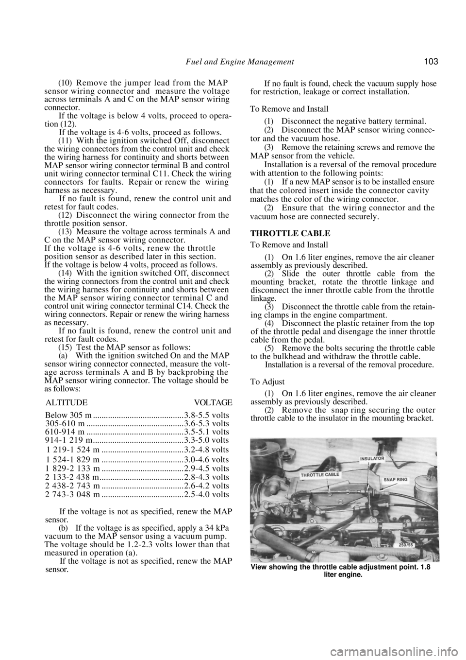
(2) Remove the snap ring securing the outer
throttle cable to the insulator in the mounting bracket.
View showing the throttle cable adjustment point. 1.8
liter engine.
Page 104 of 238
104 Fuel and Engine Management
(3) Gently pull the outer throttle cable until the
inner cable remains taut without moving the throttle
linkage. (4) Install the snap ring into the groove
posi-
tioned second from the insulator.
(5) Depress the throttle pedal and check that the
throttle valve opens fully and returns to the idle
position when the pedal is released. (6) On 1.6 liter engines, install the air
cleaner
assembly.
7. ELECTRONIC COMPONENTS
NOTE: Before proceeding with any of the
operations in this section, refer to the Ser-
vice Precautions and Procedures heading.
TO CHECK IGNITION SYSTEM
(1) Perform the test procedure described in the
Roadside Trouble Shooting section. Repair or renew
components as necessary. (2) Perform the self diagnosis test procedure as
previously described and rectify any faults. If there is
no spark, proceed as follows. (3) Disconnect the 4 pin wiring connector from
the distributor and check for spark at a spark plug
high tension lead using the test spark plug. If there is a spark, renew the pickup coil in the
distributor.
If there is no spark, proceed as follows.
(4) Connect the coil high tension lead to the test
spark plug and check for spark.
If there is a spark, check the distributor cap and
rotor for cracks and moisture. Repair or renew as
necessary.
If there is no spark, proceed as follows.
(5) Disconnect the 2 pin wiring connector from
the distributor. (6) With the ignition switched On. measure the
voltage at terminals A and B on the distributor 2 pin
wiring connector. If the voltage at terminal B only is under 10 volts,
check the wiring harness for continuity between
terminal B on the distributor 2 pin wiring connector
and terminal 2 on the black ignition coil wiring
connector. Repair or renew the wiring harness as
necessary. If no fault is found, renew the ignition coll.
If the voltages at both terminals is under 10 volts,
check the wiring harness between terminal A on the
distributor 2 pin wiring connector and terminal 1 on
the black ignition coil wiring connector for continuity.
Also check the fuel pump fuse and the wiring harness
between the ignition switch and the ignition coil.
Repair or renew the wiring harness as necessary.
If the voltage at both terminals is 10 volts or
more, proceed as follows.
(7) Connect the 2 pin wiring connector to the
distributor. (8) With the ignition switched On, measure the
voltage at the tachometer signal wire.
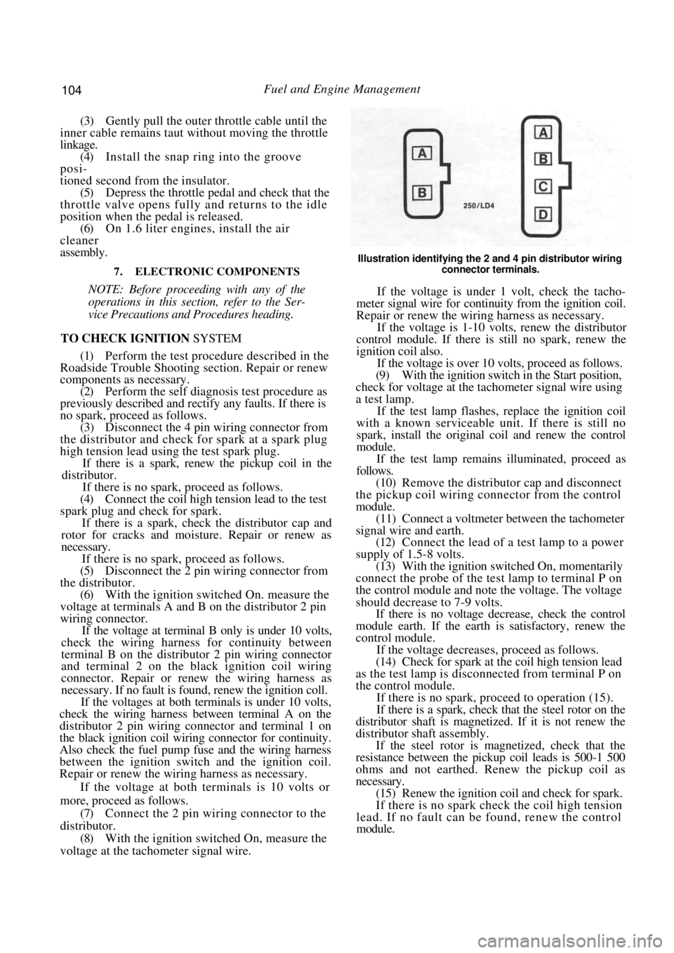
Illustration identifying the 2 and 4 pin distributor wiring
connector terminals.
If the voltage is under 1 volt, check the tacho-
meter signal wire for continuity from the ignition coil.
Repair or renew the wiring harness as necessary.
If the voltage is 1-10 volts, renew the distributor
control module. If there is still no spark, renew the
ignition coil also.
If the voltage is over 10 volts, proceed as follows.
(9) With the ignition switch in the Start position,
check for voltage at the tachometer signal wire using
a test lamp.
If the test lamp flashes, replace the ignition coil
with a known serviceable un it. If there is still no
spark, install the original coil and renew the control
module.
If the test lamp remains illuminated, proceed as
follows.
(10) Remove the distributor cap and disconnect
the pickup coil wiring co nnector from the control
module. (11) Connect a voltmeter between the tachometer
signal wire and earth. (12) Connect the lead of a test lamp to a power
supply of 1.5-8 volts. (13) With the ignition switched On, momentarily
connect the probe of the test lamp to terminal P on
the control module and note the voltage. The voltage
should decrease to 7-9 volts. If there is no voltage decrease, check the control
module earth. If the earth is satisfactory, renew the
control module.
If the voltage decreases , proceed as follows.
(14) Check for spark at the coil high tension lead
as the test lamp is disconnected from terminal P on
the control module.
If there is no spark, proceed to operation (15).
If there is a spark, check that the steel rotor on the
distributor shaft is magnetized. If it is not renew the
distributor shaft assembly.
If the steel rotor is magnetized, check that the
resistance between the pickup coil leads is 500-1 500
ohms and not earthed. Renew the pickup coil as
necessary.
(15) Renew the ignition coil and check for spark.
If there is no spark check the coil high tension
lead. If no fault can be found, renew the control
module.
Page 105 of 238
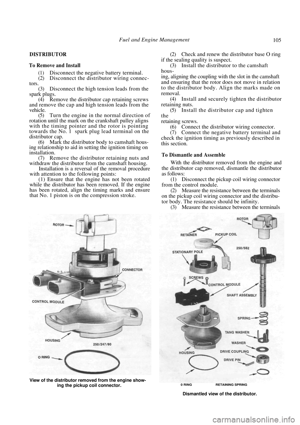
Fuel and Engine Management 105
DISTRIBUTOR
To Remove and Install
(1) Disconnect the negative battery terminal.
(2) Disconnect the distribu tor wiring connec-
tors.
(3) Disconnect the high tension leads from the
spark plugs. (4) Remove the distributor cap retaining screws
and remove the cap and high tension leads from the
vehicle. (5) Turn the engine in the normal direction of
rotation until the mark on the crankshaft pulley aligns
with the timing pointer and the rotor is pointing
towards the No. 1 spark pl ug lead terminal on the
distributor cap. (6) Mark the distributor body to camshaft hous-
ing relationship to aid in setting the ignition timing on
installation.
(7) Remove the distributor retaining nuts and
withdraw the distributor from the camshaft housing.
Installation is a reversal of the removal procedure
with attention to the following points:
(1) Ensure that the engine has not been rotated
while the distributor has been removed. If the engine
has been rotated, align the timing marks and ensure
that No. 1 piston is on the compression stroke.
(2) Check and renew the distributor base O ring
if the sealing quality is suspect. (3) Install the distributor to the camshaft
hous-
ing, aligning the coupling with the slot in the camshaft
and ensuring that the rotor does not move in relation
to the distributor body. Align the marks made on
removal. (4) Install and securely tighten the distributor
retaining nuts. (5) Install the distributor cap and tighten
the
retaining screws.
(6) Connect the distributor wiring connector.
(7) Connect the negative battery terminal and
check the ignition timing as previously described in
this section.
To Dismantle and Assemble
With the distributor removed from the engine and
the distributor cap removed, dismantle the distributor
as follows:
(1) Disconnect the pickup coil wiring connector
from the control module. (2) Measure the resistance between the terminals
on the pickup coil wiring connector and the distribu-
tor body. The r esistance should be infinity.
(3) Measure the resistance between the terminals
View of the distributor removed from the engine show-
ing the pickup coil connector. 0 RING RETAINING SPRING
Dismantled view of the distributor.
Page 106 of 238
106 Fuel and Engine Management
on the pickup coil wiring connector. The resistance
should be 500-1 500 ohms.
If the resistance is not as specified in either of the
above tests, renew the pickup coil.
(4) Remove the retaining spring from the dis-
tributor drive coupling.
(5) Using a pin punch, remove the drive pin
from the shaft. (6) Remove the drive coupling, washer, tang
washer and thrust spring from the shaft. (7) Remove the rotor and sh aft from the distrib-
utor housing. (8) Remove the retainer from the distributor
housing and withdraw the pickup coil. (9) Remove the retaining sc rews and remove the
control module from the distributor body. (10) Carefully lever the stationary pole from the
housing using a suitable screwdriver. Assembly is a reversal of the dismantling proce-
dure with attention to the following points:
(1) Ensure that the mating surfaces of the dis-
tributor housing and the control module are clean.
(2) Apply a silicone heat sink compound to the
surfaces between the control module and the distrib-
utor housing.
IGNITION COIL
To Test
(1) Disconnect the grey wiring connector and the
black wiring connector from the ignition coil in that
order. (2) Measure the resistance between coil terminal
I and the coil body. There should be a high resistance. (3) Measure the resistance between coil termi-
nals 2 and 4. There should be a low resistance. (4) Measure the resistance between coil terminal
3 and the high tension termin al. The resistance should
be other than infinity.
If any of the tests indicate a fault, renew the
ignition coil.
To Remove and Install
(1) Disconnect the negative battery terminal.
(2) Disconnect the grey wiring connector and the
black wiring connector from the ignition coil in that
order. Disconnect the high tension lead. (3) Remove the coil mounting bracket retaining
bolts and remove the coil and bracket from the
engine. Installation is a reversal of the removal procedure.
ELECTRONIC SPARK TIMING
To Test - Code 42
(1) Erase the self diagnosis code memory as
previously described. (2) Start and run the engine at idle speed for 60
seconds or until the ECM warning lamp lights.
(3) Stop the engine, switch the ignition On and
connect a jumper lead between terminals A and B on
the diagnostic link connector . Note any fault codes
displayed. If code 42 is displayed, proceed to operation (4).
If code 42 is not displayed, but was displayed
when the self diagnosis test procedure was originally
performed, an intermittent fault is indicated. Proceed
as follows:
(a) Check for faulty wiri ng connections. Check
that all wiring connectors are clean and secure.
(b) Check that all earth wires are secure.
(4) With the ignition switched Off, disconnect
the control unit wiring connectors. (5) With the ignition switched On, measure the
resistance between the contro l unit wiring connector
terminal D4 and a good earthing point. The resistance
should be less than 500 ohms.
If the ohmmeter reading is as specified, check the
wiring harness between the distributor 4 pin wiring
connector terminal D and the control unit wiring
connector terminal D4 for continuity. Repair or
renew the wiring harness as necessary. Also ensure
that the distributor 4 pin wiring connector is making
good contact when connected to the distributor.
If no fault can be found, renew the ignition
control module.
If the resistance is as specified proceed as follows.
(6) With the lead of a test lamp connected to the
positive battery terminal, backprobe the control unit
wiring connector terminal D5.
If the test lamp does not light, proceed to
operation (7).
If the test lamp lights, disconnect the 4 pin wiring
connector from the distributor. If the test lamp
remains illuminated check the wiring harness between
the distributor 4 pin wiring connector terminal B and
the control unit wiring connector terminal D5 for
shorts to earth. Repair or renew the wiring harness as
necessary. If the test lamp extinguishes, renew the
ignition system control module.
(7) Connect an ohmmeter between the control
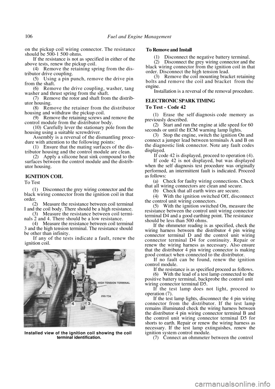
Installed view of the ignition coil showing the coil
terminal identification.
Page 107 of 238
Fuel and Engine Management 107
unit wiring connector terminal D4 and a good earth-
ing point.
(8) With the lead of a test lamp connected to the
positive battery terminal, backprobe the control unit
wiring connector terminal D5. As the test lamp probe
touches the terminal, the ohmmeter reading should
change from less than 500 ohms to over 5 000 ohms.
If the ohmmeter reading is not as specified,
proceed to operation (9).
If the ohmmeter reading is as specified, switch the
ignition Off and install the control unit wiring connec-
tors. Run the engine for 60 seconds or until the ECM
warning lamp lights and check for fault codes.
If code 42 is displayed renew the control unit.
If code 42 is not displayed, check the wiring
harness for continuity or sh orts between the control
unit wiring connector terminals D4 and D5 and the
distributor 4 pin wiring connector terminals D and B.
(9) Disconnect the 4 pin wiring connector from
the distributor.
(10) Check for continuity between the control
unit wiring connector termin al D4 and a good earth-
ing point. There should be no continuity.
If the continuity is not as specified, check the
wiring harness between the distributor 4 pin wiring
connector terminal D and the control unit wiring
connector terminal D4 for shorts to earth. Repair or
renew the wiring harness as necessary.
If the continuity is as specified, check the wiring
harness between the distributor 4 pin wiring connec-
tor terminal B and the control unit wiring connector
terminal D5 for continuity. Repair or renew the
wiring harness as necessary. If no fault is found, renew
the ignition system control module.
CONTROL UNIT
To Test Input Circuits — Code 55
(1) Switch the ignition On with the engine
stopped and note the ECM warning lamp. (2) If a steady light is showing, proceed to
operation (3). If code 55 is displayed, proceed as follows:
(a) Switch the ignition Off and disconnect the
wiring connector from the control unit.
(b) Switch the ignition On and measure the
voltage at the wiring connector on terminals C10,
C I 1 , C12, C13 and A9. Disregard terminal C12 on
1.6 liter engines. (c) If there is voltage at any of the terminals
tested above, a faulty wi ring harness is indicated.
Repair the short circuit to voltage and return to
operation (1). (d) If there is no voltage at any of the terminals
tested, a faulty control unit is indicated. Renew the
control unit and return to operation ( 1 ) . (3) Connect a jumper lead between terminals A
and B on the diagnostic link connector and note if
code 55 is displayed.
If code 55 is displayed, an intermittent fault is
indicated. Switch Off the engine, erase the self diag-
nosis codes and run the engine for 2 minutes. Return
to operation (1 ) and repeat the test procedures.
If code 55 continues to return, renew the control
unit.
To Remove and Install
(1) Disconnect the negative battery terminal.
(2) Slide the passengers front seat to the rear-
most position and working under the seat, disconnect
the control unit wiring connectors. (3) Disengage the plastic control unit cover from
the mounting plate and remove the control unit from
the vehicle. (4) If necessary, remove the screws retaining the
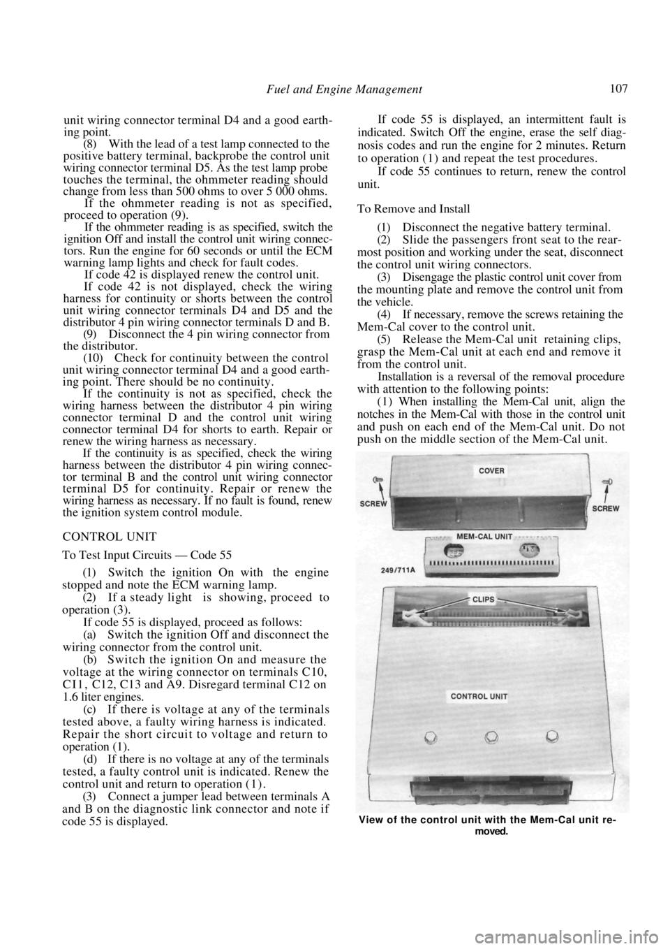
Mem-Cal cover to the control unit.
(5) Release the Mem-Cal unit retaining clips,
grasp the Mem-Cal unit at each end and remove it
from the control unit. Installation is a reversal of the removal procedure
with attention to the following points:
(1) When installing the Mem-Cal unit, align the
notches in the Mem-Cal with those in the control unit
and push on each end of the Mem-Cal unit. Do not
push on the middle section of the Mem-Cal unit.
View of the control unit with the Mem-Cal unit re-
moved.
Page 108 of 238
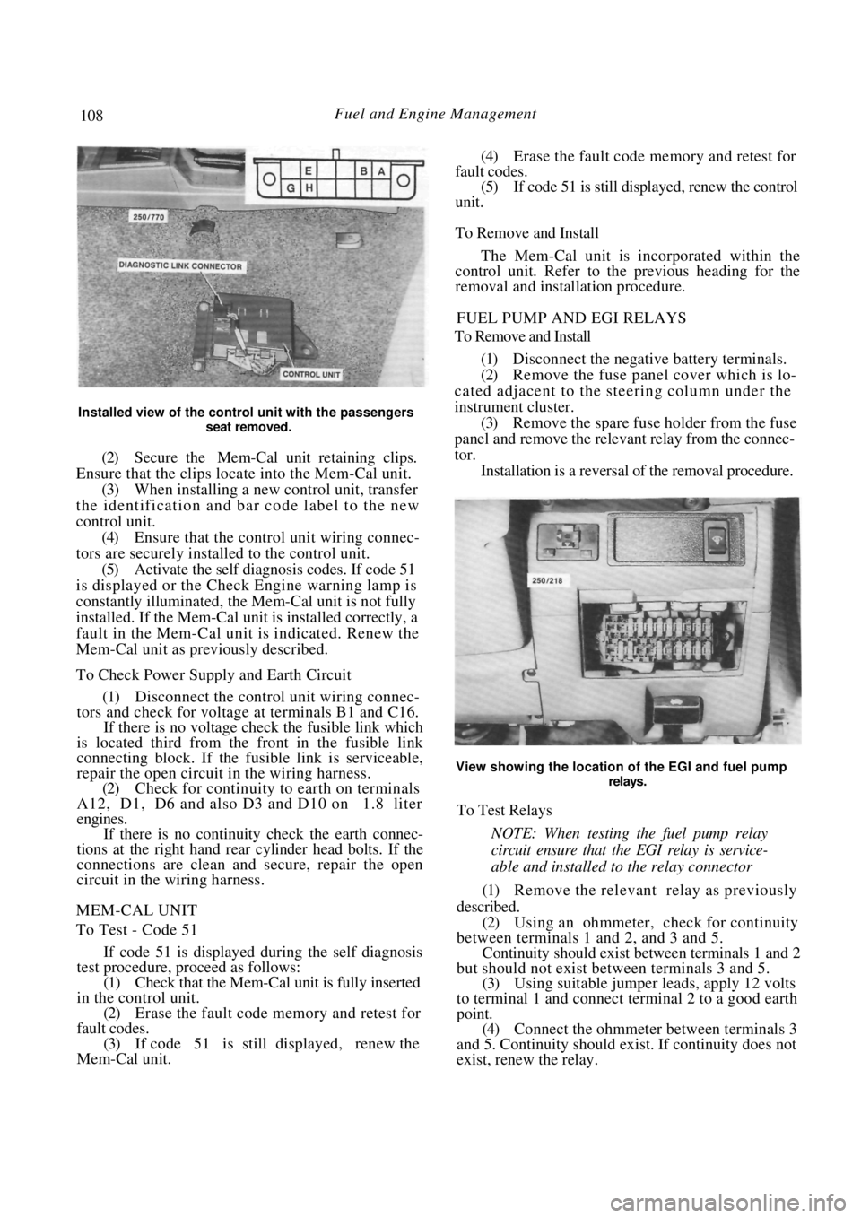
108 Fuel and Engine Management
Installed view of the control unit with the passengers seat removed.
(2) Secure the Mem-Cal unit retaining clips.
Ensure that the clips locate into the Mem-Cal unit. (3) When installing a new control unit, transfer
the identification and bar code label to the new
control unit. (4) Ensure that the control unit wiring connec-
tors are securely installed to the control unit. (5) Activate the self diagnosis codes. If code 51
is displayed or the Check Engine warning lamp is
constantly illuminated, the Mem-Cal unit is not fully
installed. If the Mem-Cal uni t is installed correctly, a
fault in the Mem-Cal unit is indicated. Renew the
Mem-Cal unit as previously described.
To Check Power Supply and Earth Circuit
(1) Disconnect the control unit wiring connec-
tors and check for voltage at terminals B1 and C16.
If there is no voltage check the fusible link which
is located third from the front in the fusible link
connecting block. If the fu sible link is serviceable,
repair the open circuit in the wiring harness.
(2) Check for continuity to earth on terminals
A12, D1, D6 and also D3 and D10 on 1.8 liter
engines.
If there is no continuity check the earth connec-
tions at the right hand rear cylinder head bolts. If the
connections are clean and secure, repair the open
circuit in the wiring harness.
MEM-CAL UNIT
To Test - Code 51
If code 51 is displayed during the self diagnosis
test procedure, pr oceed as follows:
(1) Check that the Mem-Cal unit is fully inserted
in the control unit. (2) Erase the fault code memory and retest for
fault codes. (3) If code 51 is still displayed, renew the
Mem-Cal unit.
(4) Erase the fault code memory and retest for
fault codes. (5) If code 51 is still displayed, renew the control
unit.
To Remove and Install
The Mem-Cal unit is incorporated within the
control unit. Refer to the previous heading for the
removal and installation procedure.
FUEL PUMP AND EGI RELAYS
To Remove and Install
(1) Disconnect the negative battery terminals.
(2) Remove the fuse panel cover which is lo-
cated adjacent to the steering column under the
instrument cluster. (3) Remove the spare fuse holder from the fuse
panel and remove the releva nt relay from the connec-
tor. Installation is a reversal of the removal procedure.
View showing the location of the EGI and fuel pump
relays.
To Test Relays
NOTE: When testing the fuel pump relay
circuit ensure that th e EGI relay is service-
able and installed to the relay connector
(1) Remove the relevant relay as previously
described. (2) Using an ohmmeter, check for continuity
between terminals 1 and 2, and 3 and 5. Continuity should exist be tween terminals 1 and 2
but should not exist between terminals 3 and 5.
(3) Using suitable jumper leads, apply 12 volts
to terminal 1 and connect terminal 2 to a good earth
point. (4) Connect the ohmmeter between terminals 3
and 5. Continuity should exist. If continuity does not
exist, renew the relay.
Page 109 of 238
Fuel and Engine Management 109
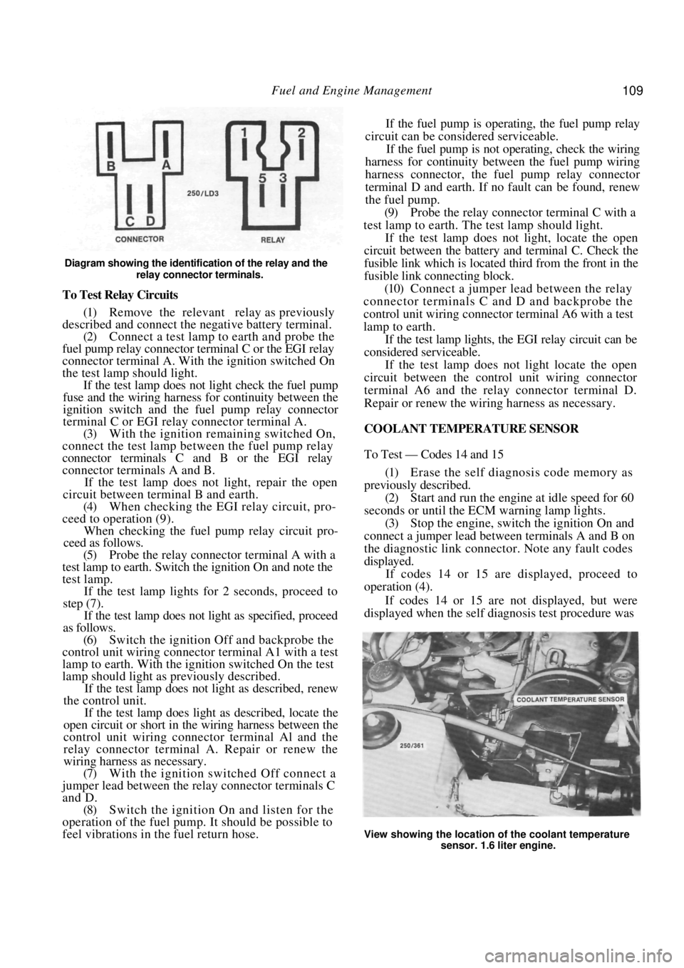
Diagram showing the identification of the relay and the relay connector terminals.
To Test Relay Circuits
(1) Remove the relevant relay as previously
described and connect the ne gative battery terminal.
(2) Connect a test lamp to earth and probe the
fuel pump relay connector terminal C or the EGI relay
connector terminal A. With the ignition switched On
the test lamp should light. If the test lamp does not light check the fuel pump
fuse and the wiring harness for continuity between the
ignition switch and the fuel pump relay connector
terminal C or EGI rela y connector terminal A.
(3) With the ignition remaining switched On,
connect the test lamp between the fuel pump relay
connector terminals C and B or the EGI relay
connector terminals A and B.
If the test lamp does not light, repair the open
circuit between terminal B and earth.
(4) When checking the EGI relay circuit, pro-
ceed to operation (9).
When checking the fuel pu mp relay circuit pro-
ceed as follows.
(5) Probe the relay connector terminal A with a
test lamp to earth. Switch the ignition On and note the
test lamp.
If the test lamp lights for 2 seconds, proceed to
step (7).
If the test lamp does not light as specified, proceed
as follows.
(6) Switch the ignition Off and backprobe the
control unit wiring connector terminal A1 with a test
lamp to earth. With the ignition switched On the test
lamp should light as previously described.
If the test lamp does not light as described, renew
the control unit.
If the test lamp does light as described, locate the
open circuit or short in the wiring harness between the
control unit wiring connector terminal Al and the
relay connector terminal A. Repair or renew the
wiring harness as necessary.
(7) With the ignition switched Off connect a
jumper lead between the relay connector terminals C
and D. (8) Switch the ignition On and listen for the
operation of the fuel pump. It should be possible to
feel vibrations in the fuel return hose. If the fuel pump is operating, the fuel pump relay
circuit can be considered serviceable.
If the fuel pump is not operating, check the wiring
harness for continuity between the fuel pump wiring
harness connector, the fuel pump relay connector
terminal D and earth. If no fault can be found, renew
the fuel pump.
(9) Probe the relay connector terminal C with a
test lamp to earth. The test lamp should light.
If the test lamp does not light, locate the open
circuit between the battery and terminal C. Check the
fusible link which is located third from the front in the
fusible link connecting block.
(10) Connect a jumper lead between the relay
connector terminals C and D and backprobe the
control unit wiring connector terminal A6 with a test
lamp to earth.
If the test lamp lights, the EGI relay circuit can be
considered serviceable.
If the test lamp does not light locate the open
circuit between the contro l unit wiring connector
terminal A6 and the relay connector terminal D.
Repair or renew the wiring harness as necessary.
COOLANT TEMPERATURE SENSOR
To Test — Codes 14 and 15
(1) Erase the self diagnosis code memory as
previously described. (2) Start and run the engine at idle speed for 60
seconds or until the ECM warning lamp lights.
(3) Stop the engine, switch the ignition On and
connect a jumper lead between terminals A and B on
the diagnostic link connect or. Note any fault codes
displayed. If codes 14 or 15 are displayed, proceed to
operation (4).
If codes 14 or 15 are not displayed, but were
displayed when the self diagnosis test procedure was
View showing the location of the coolant temperature
sensor. 1.6 liter engine.
Page 110 of 238

110 Fuel and Engine Management
originally performed, an intermittent fault is indi-
cated. Proceed as follows:
(a) Check for faulty wiri ng connections. Check
that all wiring connectors are clean and secure. (b) Check that all earth wires are secure.
(4) Disconnect the wiring connector from the
coolant temperature sensor. (5) With the ignition switched On, measure the
voltage across the terminals on the coolant tempera-
ture sensor wiring connector. The voltage should be
4-6 volts.
If the voltage is below 4 volts, proceed to opera-
tion (9).
If the voltage is as specified, proceed as follows.
(6) Remove the coolant temperature sensor
from the vehicle. (7) Connect an ohmmeter to the coolant temper-
ature sensor terminals. (8) Immerse the meta1 end of the coolant
tem-
perature sensor in a 50/50 mixture of glycol and iced
water at a temperature of 0 deg C. The resistance
should be 6 000 ohms. Slowly heat the mixture and measure the resis-
tance of the coolant temperature sensor at the follow-
ing temperatures. Compare the results with the spec-
ified values:
0 d e g C ................................................. 6 000 ohms
20 deg C .................................................. 2 500 ohms
30 deg C .................................................. 1 800 ohms
40 deg C.................................................. 1 200 ohms
70 deg C .......................................................450 ohms
90 degC .......................................................250 ohms
100 deg C.....................................................190 ohms
110 deg C.....................................................110 ohms
If the resistances obtained are not as specified at
any of the given temperatures, renew the coolant
temperature sensor and retest for fault codes.
(9) Disconnect the control unit wiring connec-
tors.
(10) Check the wiring harness for shorts and
continuity between the coolant temperature sensor
wiring connector terminals and the control unit wiring
connector terminals C10 and D2. Repair or renew the
wiring harness as necessary.
Also check the control unit terminals for damage.
If no fault is found, renew the control unit and
retest for fault codes.
To Remove and Install
(1) Disconnect the negative battery terminal.
(2) Disconnect the wiring connector from the
coolant temperature sensor.
(3) Drain the coolant as described in the Cooling
and Heating Systems section to a level below the
sensor.
(4) Unscrew the sensor from the thermostat
housing. Installation is a reversal of the removal procedure
with attention to the following points;
(1) Apply Loctite 675 or a similar conductive
sealer to the threads of th e sensor. Tighten the sensor
to the specified torque.
(2) Fill the cooling system with the correct
mixture of water and inhibitor as described in the
Cooling and Heating Systems section. (3) Ensure that the wiring connector is clean and
secure.
THROTTLE POSITION SENSOR
To Test - Codes 21 and 22
NOTE: The following test procedure as-
sumes that fault codes 21 or 22 have been
displayed during the se lf diagnosis test pro-
cedure. If no codes have been displayed but
the operation of the throttle position sensor
is suspect, begin the test procedure at oper-
ation (24).
(1) Erase the self diagnosis code memory as
previously described.
(2) Start and run the engine at idle speed for 60
seconds or until the ECM warning lamp lights. If the engine will not start, disconnect the throttle
position sensor wiring co nnector and proceed to
operation (8). .
(3) With the engine id ling, quickly increase the
engine speed to 3 000 rpm and return to idle.
If the ECM warning lamp remains illuminated,
proceed to operation (4).
If the ECM warning lamp extinguishes, an inter-
mittent fault is indicated. Proceed as follows:
(a) Check for faulty wiri ng connections. Check
that all wiring connectors are clean and secure. (b) Check that all earth wires are secure.
(4) Stop the engine, switch the ignition On and
connect a jumper lead between terminals A and B on
the diagnostic link connect or. Note any fault codes
displayed.
If codes 21 or 22 are displayed, proceed as
follows.
(5) Remove the jumper lead from the diagnostic
link connector. (6) Erase the self diagnosis codes as previously
described. (7) Disconnect the wiring connector from the
throttle position sensor. If code 22 was displayed in operation (4), proceed
to operation (13).
If code 21 was displayed in operation (4), proceed
as follows.
(8) Start and run the engine at idle speed for 2
minutes or until the ECM warning lamp lights. If the
engine will not start, pr oceed to operation (11).
(9) Stop the engine, switch the ignition On and
connect a jumper lead between terminals A and B on