NISSAN TERRANO 2002 Service Repair Manual
TERRANO 2002
NISSAN
NISSAN
https://www.carmanualsonline.info/img/5/57393/w960_57393-0.png
NISSAN TERRANO 2002 Service Repair Manual
Trending: glove box, lights, ECO mode, handbrake, checking oil, radio antenna, fuel pump
Page 141 of 1767
DISASSEMBLY
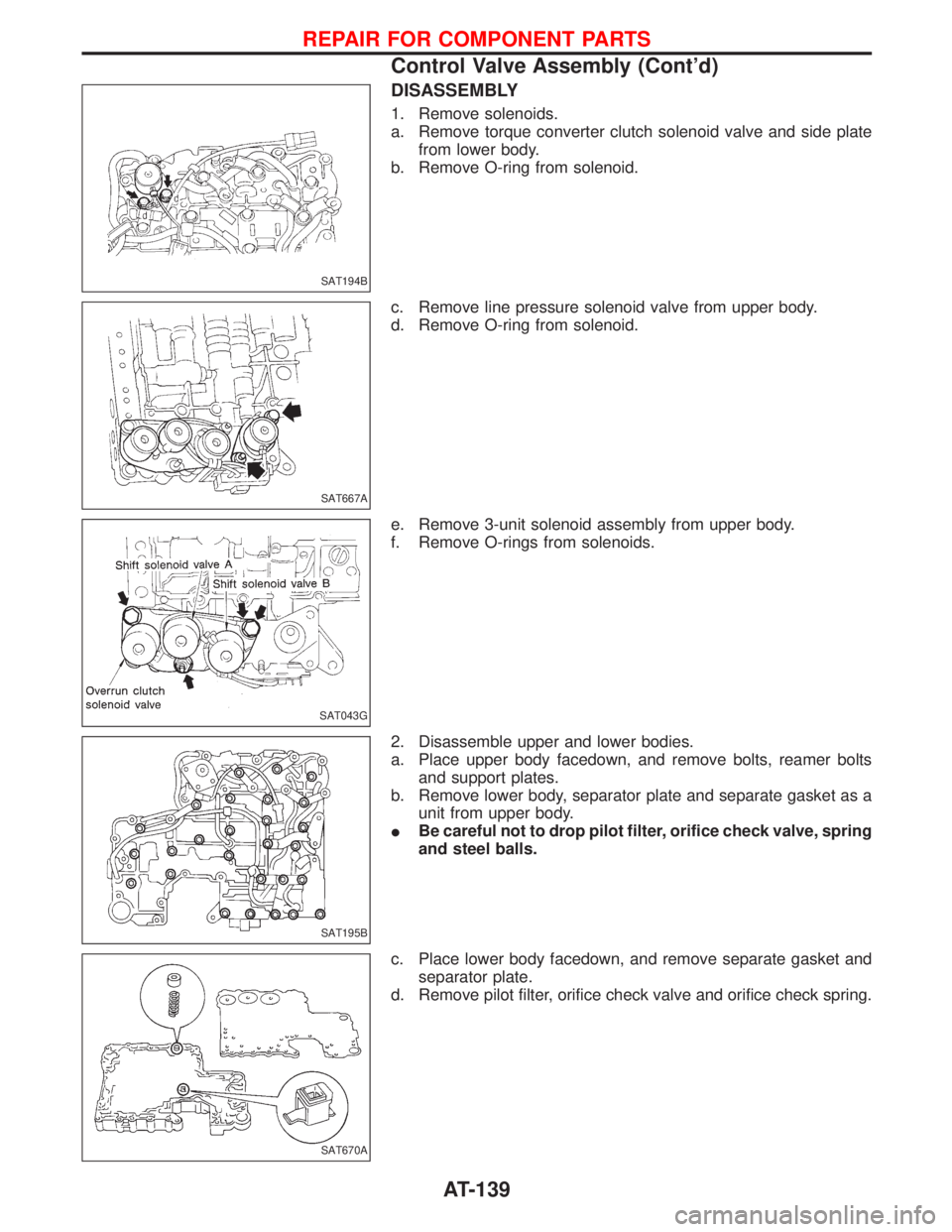
1. Remove solenoids.
a. Remove torque converter clutch solenoid valve and side plate
from lower body.
b. Remove O-ring from solenoid.
c. Remove line pressure solenoid valve from upper body.
d. Remove O-ring from solenoid.
e. Remove 3-unit solenoid assembly from upper body.
f. Remove O-rings from solenoids.
2. Disassemble upper and lower bodies.
a. Place upper body facedown, and remove bolts, reamer bolts
and support plates.
b. Remove lower body, separator plate and separate gasket as a
unit from upper body.
IBe careful not to drop pilot filter, orifice check valve, spring
and steel balls.
c. Place lower body facedown, and remove separate gasket and
separator plate.
d. Remove pilot filter, orifice check valve and orifice check spring.
SAT194B
SAT667A
SAT043G
SAT195B
SAT670A
REPAIR FOR COMPONENT PARTS
Control Valve Assembly (Cont'd)
AT-139
Page 142 of 1767
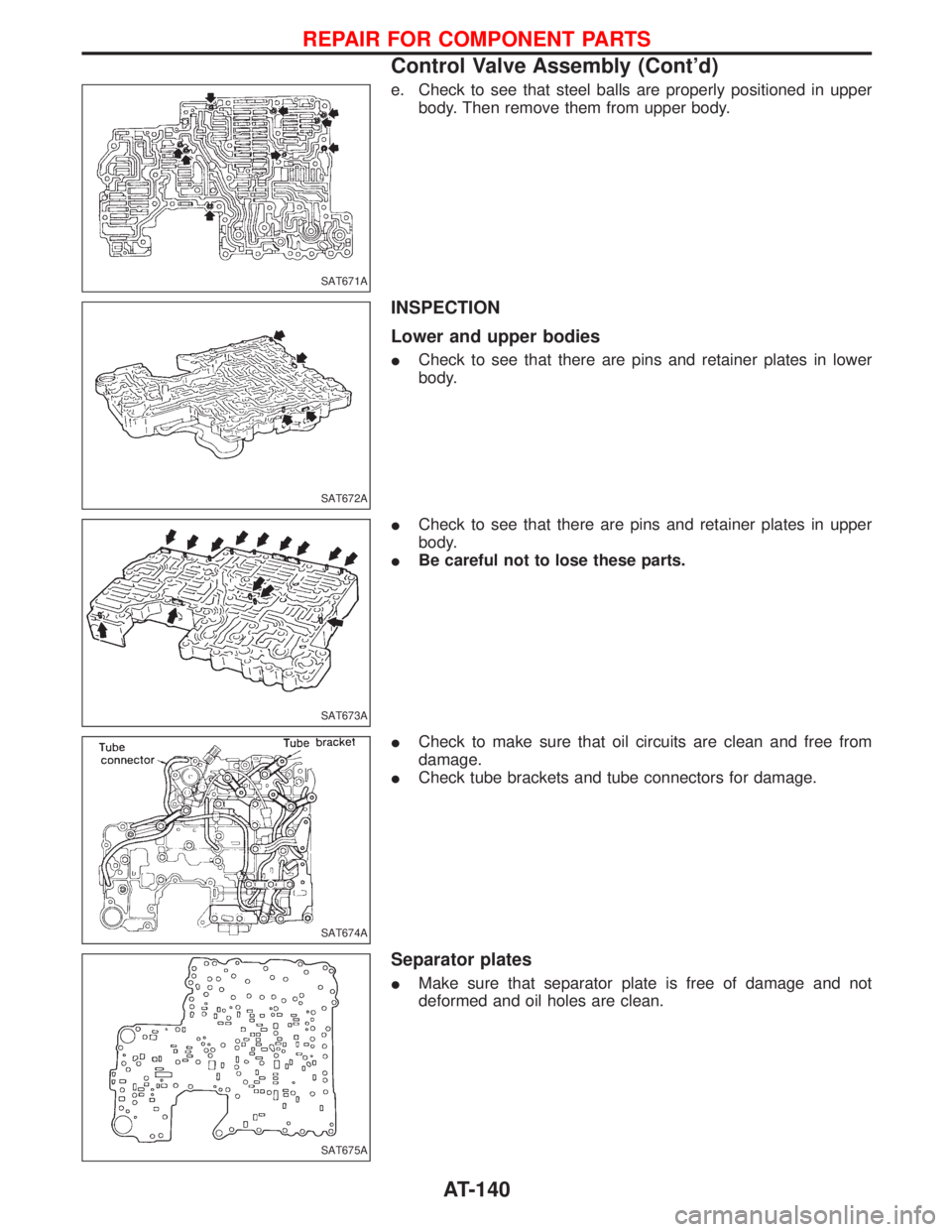
e. Check to see that steel balls are properly positioned in upper
body. Then remove them from upper body.
INSPECTION
Lower and upper bodies
ICheck to see that there are pins and retainer plates in lower
body.
ICheck to see that there are pins and retainer plates in upper
body.
IBe careful not to lose these parts.
ICheck to make sure that oil circuits are clean and free from
damage.
ICheck tube brackets and tube connectors for damage.
Separator plates
IMake sure that separator plate is free of damage and not
deformed and oil holes are clean.
SAT671A
SAT672A
SAT673A
SAT674A
SAT675A
REPAIR FOR COMPONENT PARTS
Control Valve Assembly (Cont'd)
AT-140
Page 143 of 1767
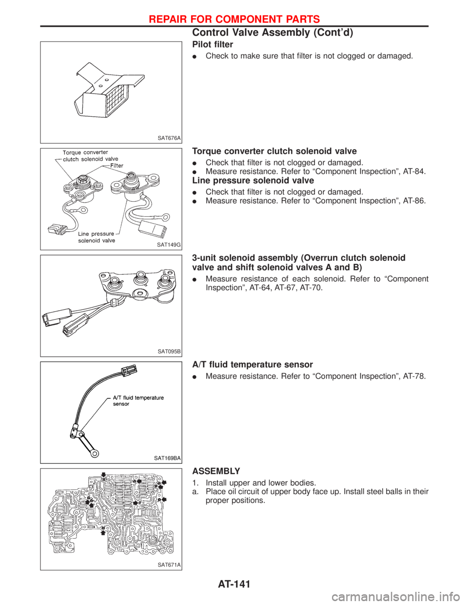
Pilot filter
ICheck to make sure that filter is not clogged or damaged.
Torque converter clutch solenoid valve
ICheck that filter is not clogged or damaged.
IMeasure resistance. Refer to ªComponent Inspectionº, AT-84.
Line pressure solenoid valve
ICheck that filter is not clogged or damaged.
IMeasure resistance. Refer to ªComponent Inspectionº, AT-86.
3-unit solenoid assembly (Overrun clutch solenoid
valve and shift solenoid valves A and B)
IMeasure resistance of each solenoid. Refer to ªComponent
Inspectionº, AT-64, AT-67, AT-70.
A/T fluid temperature sensor
IMeasure resistance. Refer to ªComponent Inspectionº, AT-78.
ASSEMBLY
1. Install upper and lower bodies.
a. Place oil circuit of upper body face up. Install steel balls in their
proper positions.
SAT676A
SAT149G
SAT095B
SAT169BA
SAT671A
REPAIR FOR COMPONENT PARTS
Control Valve Assembly (Cont'd)
AT-141
Page 144 of 1767
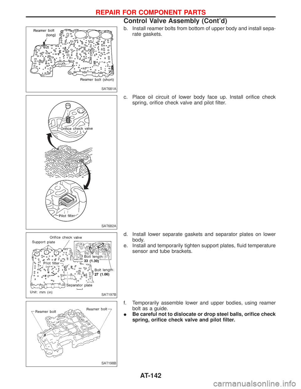
b. Install reamer bolts from bottom of upper body and install sepa-
rate gaskets.
c. Place oil circuit of lower body face up. Install orifice check
spring, orifice check valve and pilot filter.
d. Install lower separate gaskets and separator plates on lower
body.
e. Install and temporarily tighten support plates, fluid temperature
sensor and tube brackets.
f. Temporarily assemble lower and upper bodies, using reamer
bolt as a guide.
IBe careful not to dislocate or drop steel balls, orifice check
spring, orifice check valve and pilot filter.
SAT681A
SAT682A
SAT197B
SAT198B
REPAIR FOR COMPONENT PARTS
Control Valve Assembly (Cont'd)
AT-142
Page 145 of 1767
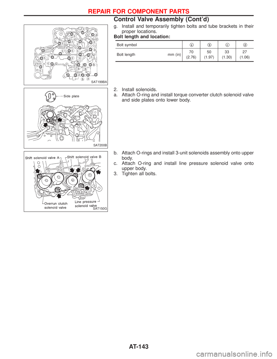
g. Install and temporarily tighten bolts and tube brackets in their
proper locations.
Bolt length and location:
Bolt symbolqaqbqcqd
Bolt length mm (in)70
(2.76)50
(1.97)33
(1.30)27
(1.06)
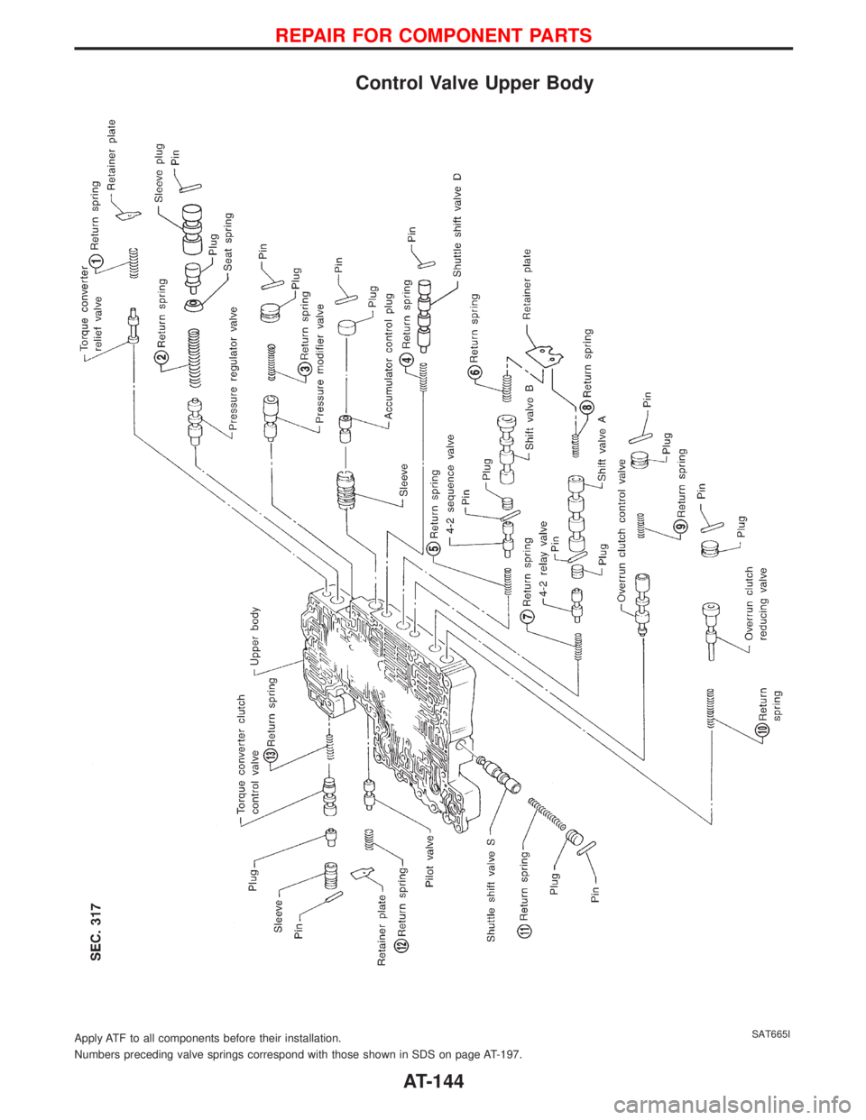
2. Install solenoids.
a. Attach O-ring and install torque converter clutch solenoid valve
and side plates onto lower body.
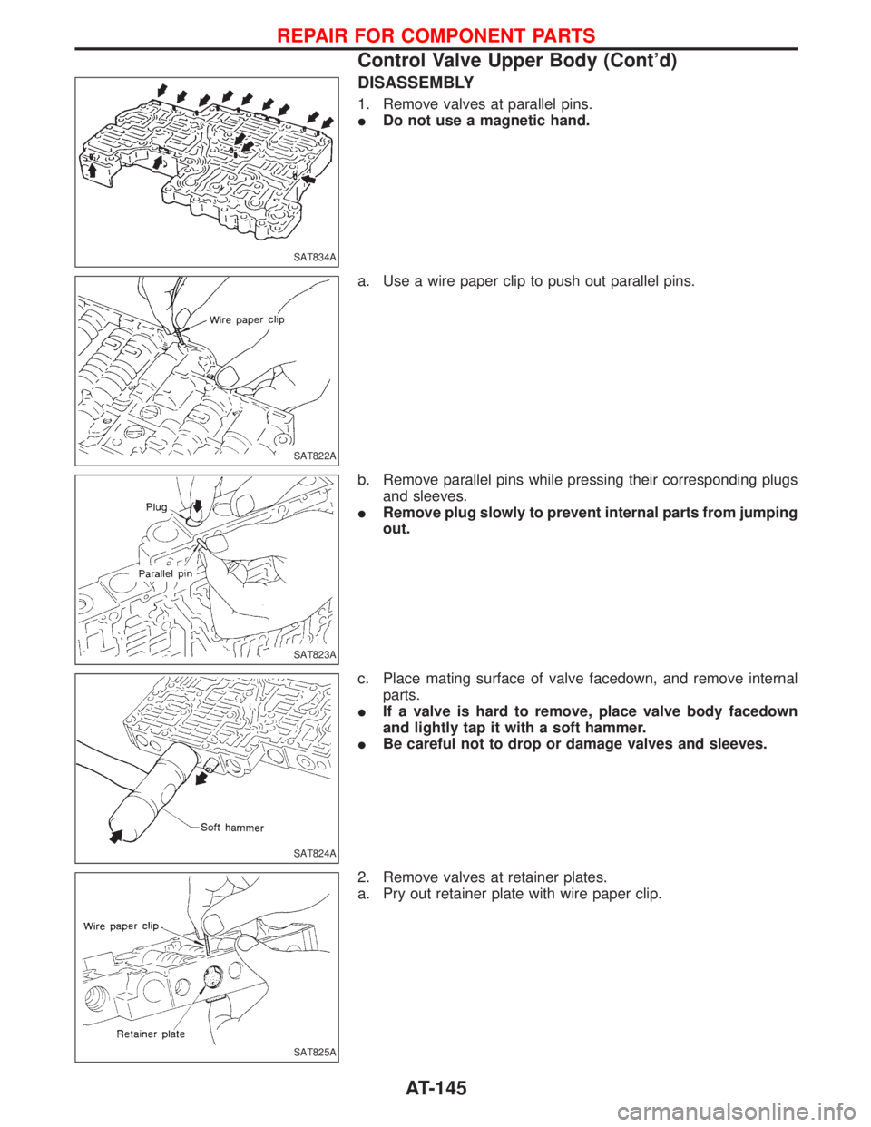
b. Attach O-rings and install 3-unit solenoids assembly onto upper
body.
c. Attach O-ring and install line pressure solenoid valve onto
upper body.
3. Tighten all bolts.
SAT199BA
SAT200B
SAT150G
REPAIR FOR COMPONENT PARTS
Control Valve Assembly (Cont'd)
AT-143
Page 146 of 1767
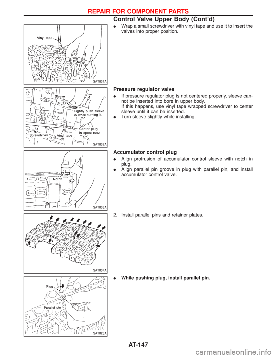
Control Valve Upper Body
Numbers preceding valve springs correspond with those shown in SDS on page AT-197. Apply ATF to all components before their installation.
SAT665I
REPAIR FOR COMPONENT PARTS
AT-144
Page 147 of 1767
DISASSEMBLY
1. Remove valves at parallel pins.
IDo not use a magnetic hand.
a. Use a wire paper clip to push out parallel pins.
b. Remove parallel pins while pressing their corresponding plugs
and sleeves.
IRemove plug slowly to prevent internal parts from jumping
out.
c. Place mating surface of valve facedown, and remove internal
parts.
IIf a valve is hard to remove, place valve body facedown
and lightly tap it with a soft hammer.
IBe careful not to drop or damage valves and sleeves.
2. Remove valves at retainer plates.
a. Pry out retainer plate with wire paper clip.
SAT834A
SAT822A
SAT823A
SAT824A
SAT825A
REPAIR FOR COMPONENT PARTS
Control Valve Upper Body (Cont'd)
AT-145
Page 148 of 1767
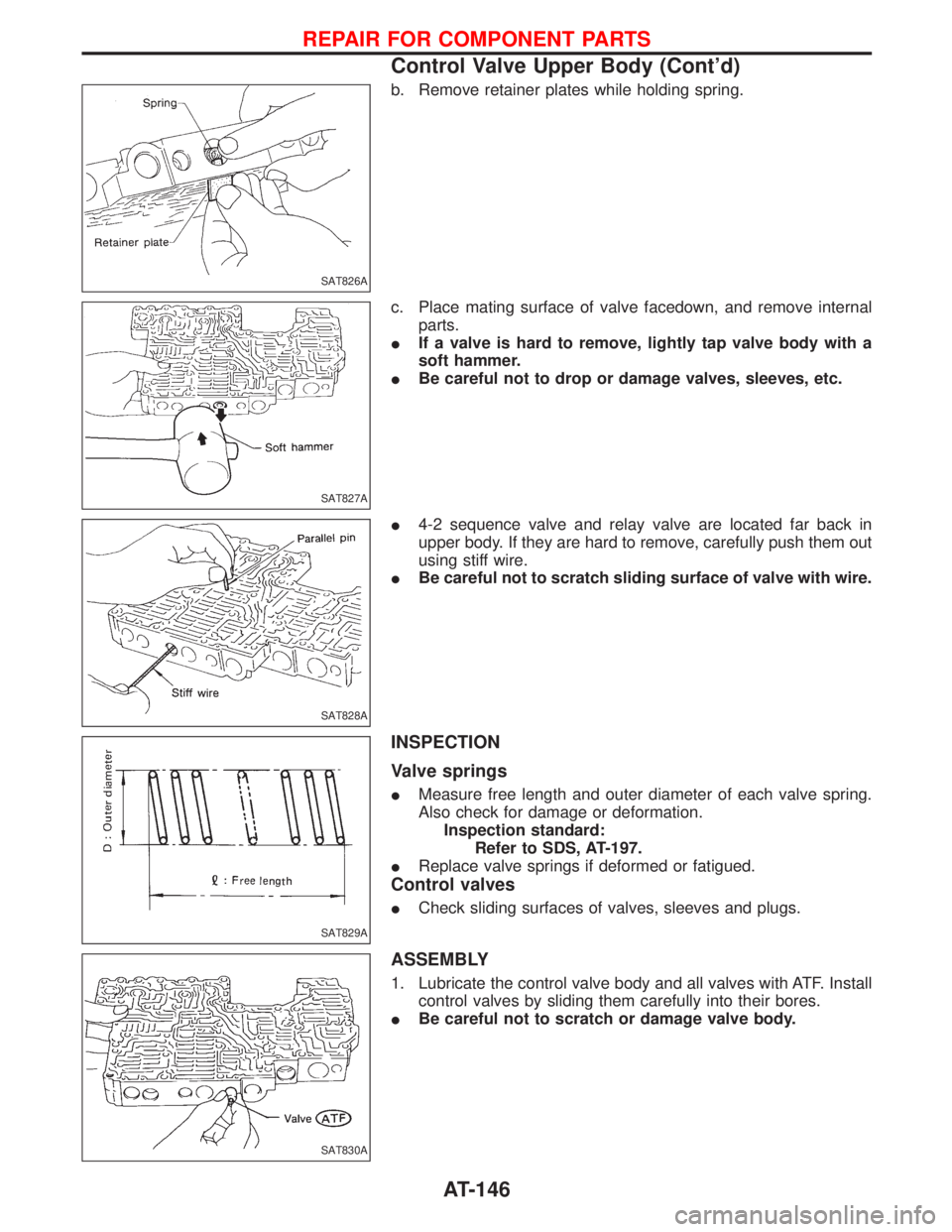
b. Remove retainer plates while holding spring.
c. Place mating surface of valve facedown, and remove internal
parts.
IIf a valve is hard to remove, lightly tap valve body with a
soft hammer.
IBe careful not to drop or damage valves, sleeves, etc.
I4-2 sequence valve and relay valve are located far back in
upper body. If they are hard to remove, carefully push them out
using stiff wire.
IBe careful not to scratch sliding surface of valve with wire.
INSPECTION
Valve springs
IMeasure free length and outer diameter of each valve spring.
Also check for damage or deformation.
Inspection standard:
Refer to SDS, AT-197.
IReplace valve springs if deformed or fatigued.
Control valves
ICheck sliding surfaces of valves, sleeves and plugs.
ASSEMBLY
1. Lubricate the control valve body and all valves with ATF. Install
control valves by sliding them carefully into their bores.
IBe careful not to scratch or damage valve body.
SAT826A
SAT827A
SAT828A
SAT829A
SAT830A
REPAIR FOR COMPONENT PARTS
Control Valve Upper Body (Cont'd)
AT-146
Page 149 of 1767
IWrap a small screwdriver with vinyl tape and use it to insert the
valves into proper position.
Pressure regulator valve
IIf pressure regulator plug is not centered properly, sleeve can-
not be inserted into bore in upper body.
If this happens, use vinyl tape wrapped screwdriver to center
sleeve until it can be inserted.
ITurn sleeve slightly while installing.
Accumulator control plug
IAlign protrusion of accumulator control sleeve with notch in
plug.
IAlign parallel pin groove in plug with parallel pin, and install
accumulator control valve.
2. Install parallel pins and retainer plates.
IWhile pushing plug, install parallel pin.
SAT831A
SAT832A
SAT833A
SAT834A
SAT823A
REPAIR FOR COMPONENT PARTS
Control Valve Upper Body (Cont'd)
AT-147
Page 150 of 1767
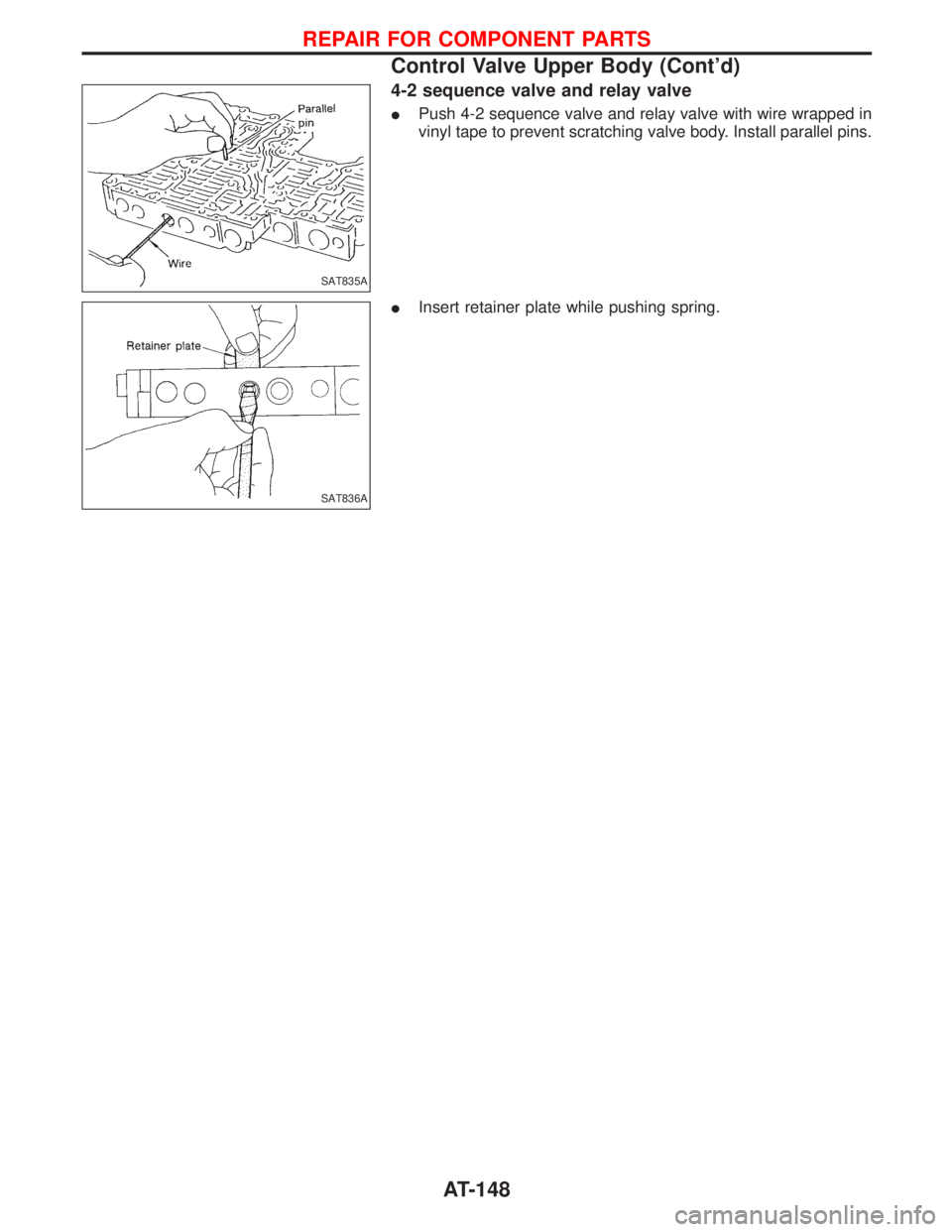
4-2 sequence valve and relay valve
IPush 4-2 sequence valve and relay valve with wire wrapped in
vinyl tape to prevent scratching valve body. Install parallel pins.
IInsert retainer plate while pushing spring.
SAT835A
SAT836A
REPAIR FOR COMPONENT PARTS
Control Valve Upper Body (Cont'd)
AT-148
Trending: wiper, compression ratio, oil, tire type, wiper relay, buttons, ESP
