NISSAN TERRANO 2002 Service Repair Manual
TERRANO 2002
NISSAN
NISSAN
https://www.carmanualsonline.info/img/5/57393/w960_57393-0.png
NISSAN TERRANO 2002 Service Repair Manual
Trending: alternator replacement, warning, Electrical system, fuel type, remote start, service reset, torque
Page 331 of 1767
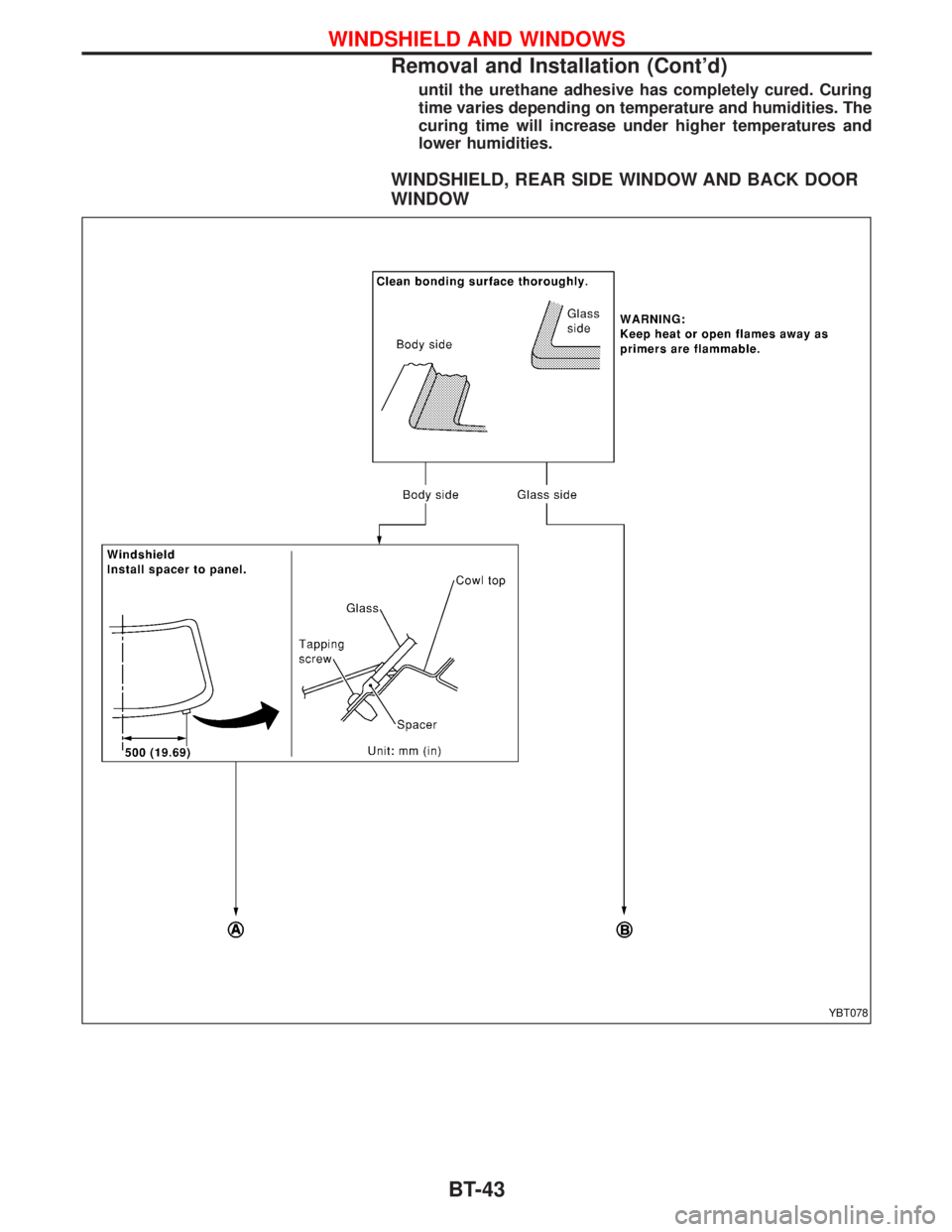
until the urethane adhesive has completely cured. Curing
time varies depending on temperature and humidities. The
curing time will increase under higher temperatures and
lower humidities.
WINDSHIELD, REAR SIDE WINDOW AND BACK DOOR
WINDOW
YBT078
WINDSHIELD AND WINDOWS
Removal and Installation (Cont'd)
BT-43
Page 332 of 1767
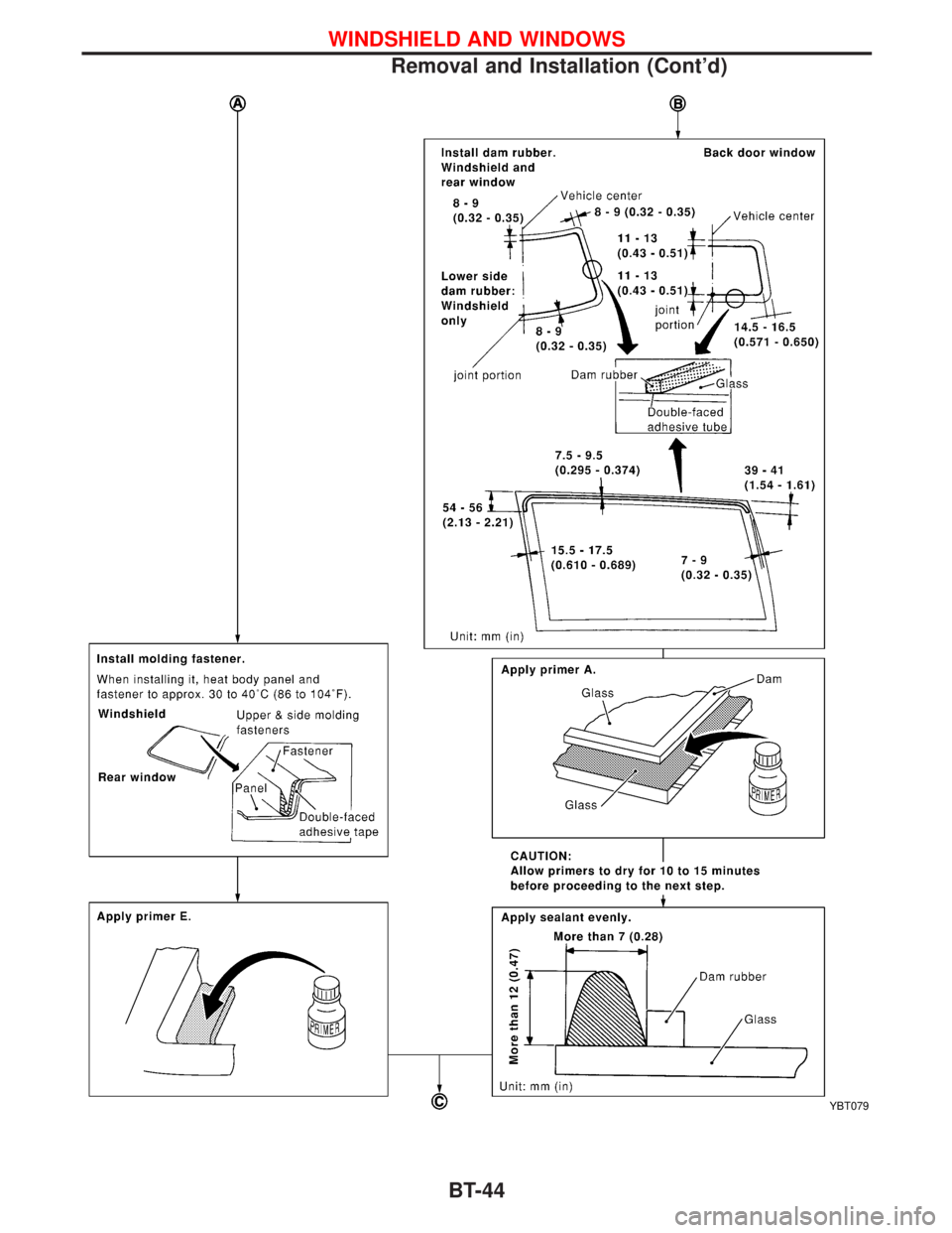
YBT079
WINDSHIELD AND WINDOWS
Removal and Installation (Cont'd)
BT-44
Page 333 of 1767
*1 BT-46
*2 BT-21
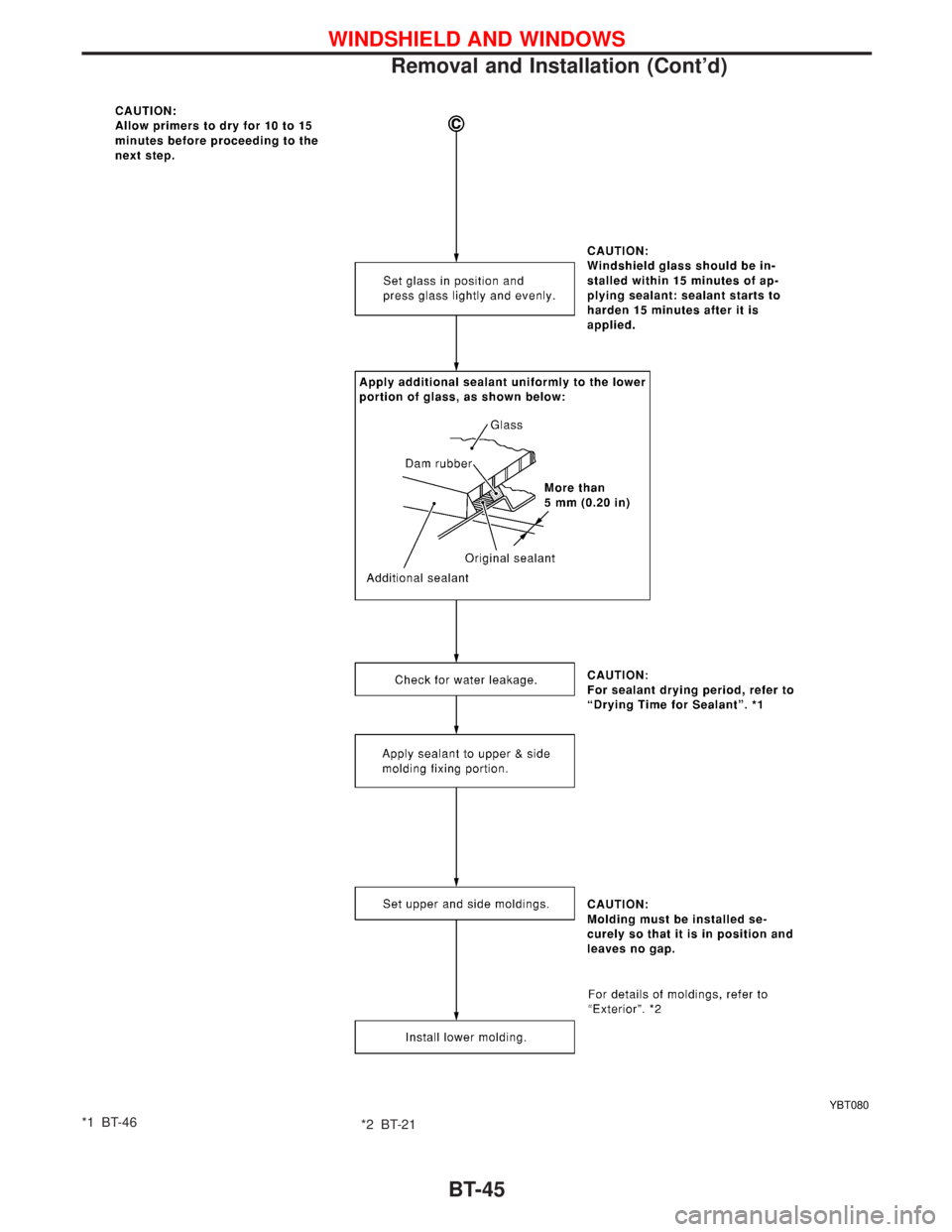
YBT080
WINDSHIELD AND WINDOWS
Removal and Installation (Cont'd)
BT-45
Page 334 of 1767
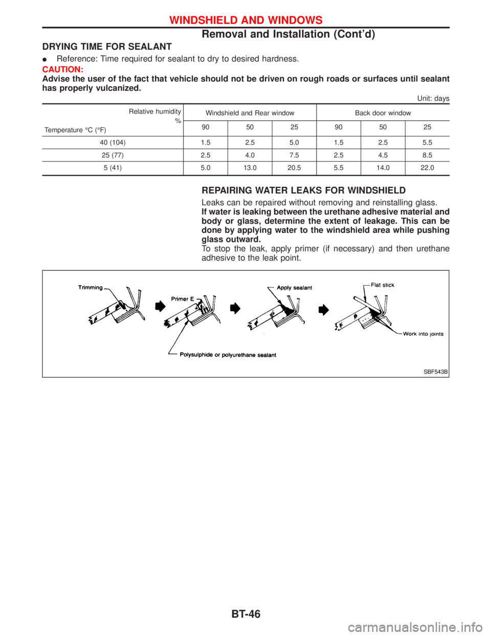
DRYING TIME FOR SEALANT
IReference: Time required for sealant to dry to desired hardness.
CAUTION:
Advise the user of the fact that vehicle should not be driven on rough roads or surfaces until sealant
has properly vulcanized.
Unit: days
Relative humidity
%
Temperature ÉC (ÉF)Windshield and Rear window Back door window
90 50 25 90 50 25
40 (104) 1.5 2.5 5.0 1.5 2.5 5.5
25 (77) 2.5 4.0 7.5 2.5 4.5 8.5
5 (41) 5.0 13.0 20.5 5.5 14.0 22.0
REPAIRING WATER LEAKS FOR WINDSHIELD
Leaks can be repaired without removing and reinstalling glass.
If water is leaking between the urethane adhesive material and
body or glass, determine the extent of leakage. This can be
done by applying water to the windshield area while pushing
glass outward.
To stop the leak, apply primer (if necessary) and then urethane
adhesive to the leak point.
SBF543B
WINDSHIELD AND WINDOWS
Removal and Installation (Cont'd)
BT-46
Page 335 of 1767
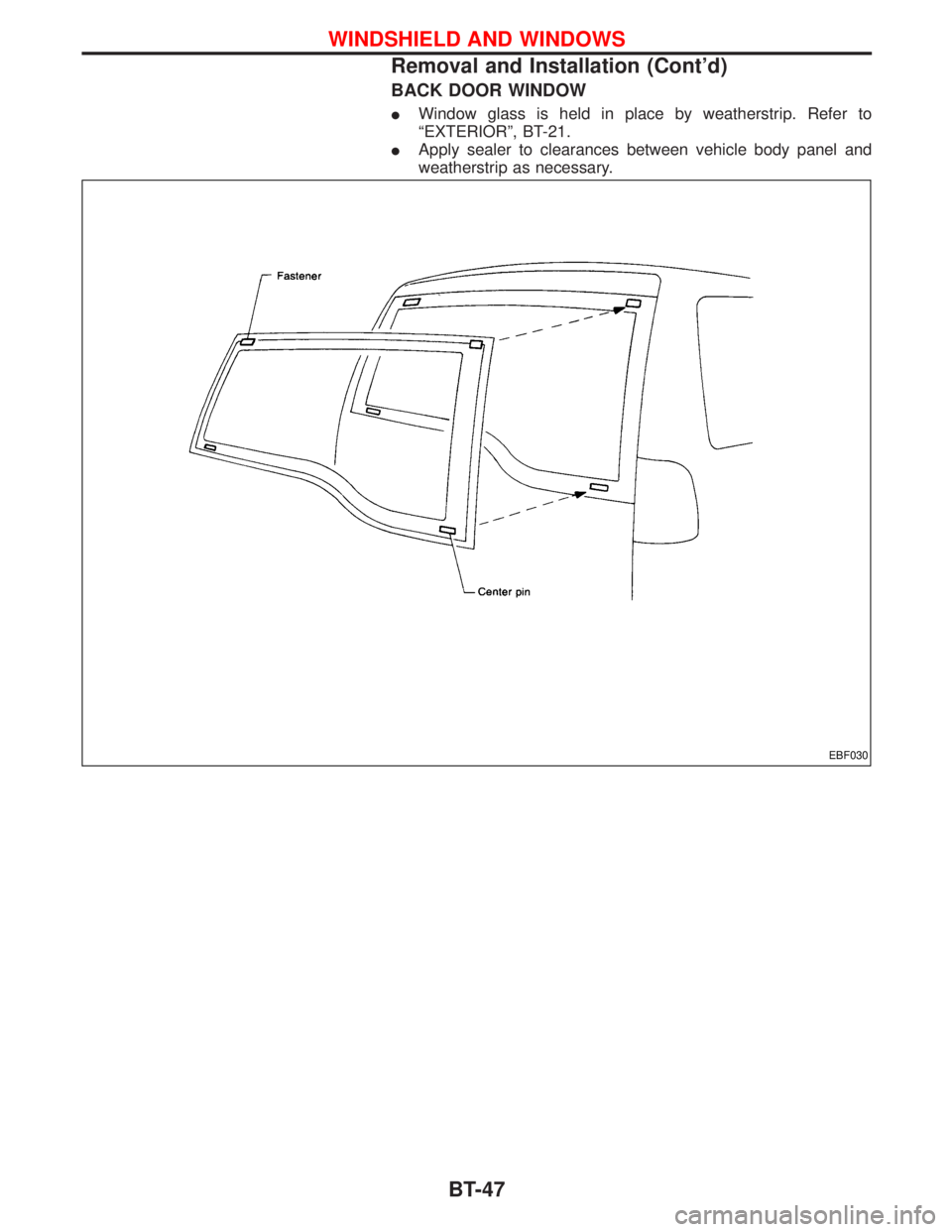
BACK DOOR WINDOW
IWindow glass is held in place by weatherstrip. Refer to
ªEXTERIORº, BT-21.
IApply sealer to clearances between vehicle body panel and
weatherstrip as necessary.
EBF030
WINDSHIELD AND WINDOWS
Removal and Installation (Cont'd)
BT-47
Page 336 of 1767
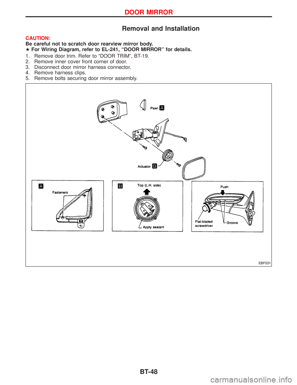
Removal and Installation
CAUTION:
Be careful not to scratch door rearview mirror body.
HFor Wiring Diagram, refer to EL-241, ªDOOR MIRRORº for details.
1. Remove door trim. Refer to ªDOOR TRIMº, BT-19.
2. Remove inner cover front corner of door.
3. Disconnect door mirror harness connector.
4. Remove harness clips.
5. Remove bolts securing door mirror assembly.
EBF031
DOOR MIRROR
BT-48
Page 337 of 1767
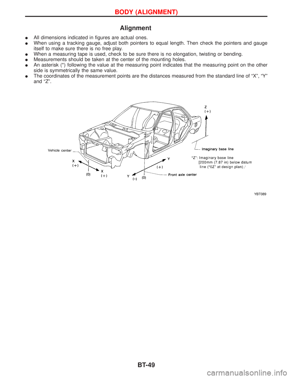
Alignment
IAll dimensions indicated in figures are actual ones.
IWhen using a tracking gauge, adjust both pointers to equal length. Then check the pointers and gauge
itself to make sure there is no free play.
IWhen a measuring tape is used, check to be sure there is no elongation, twisting or bending.
IMeasurements should be taken at the center of the mounting holes.
IAn asterisk (*) following the value at the measuring point indicates that the measuring point on the other
side is symmetrically the same value.
IThe coordinates of the measurement points are the distances measured from the standard line of ªXº, ªYº
and ªZº.
YBT089
BODY (ALIGNMENT)
BT-49
Page 338 of 1767
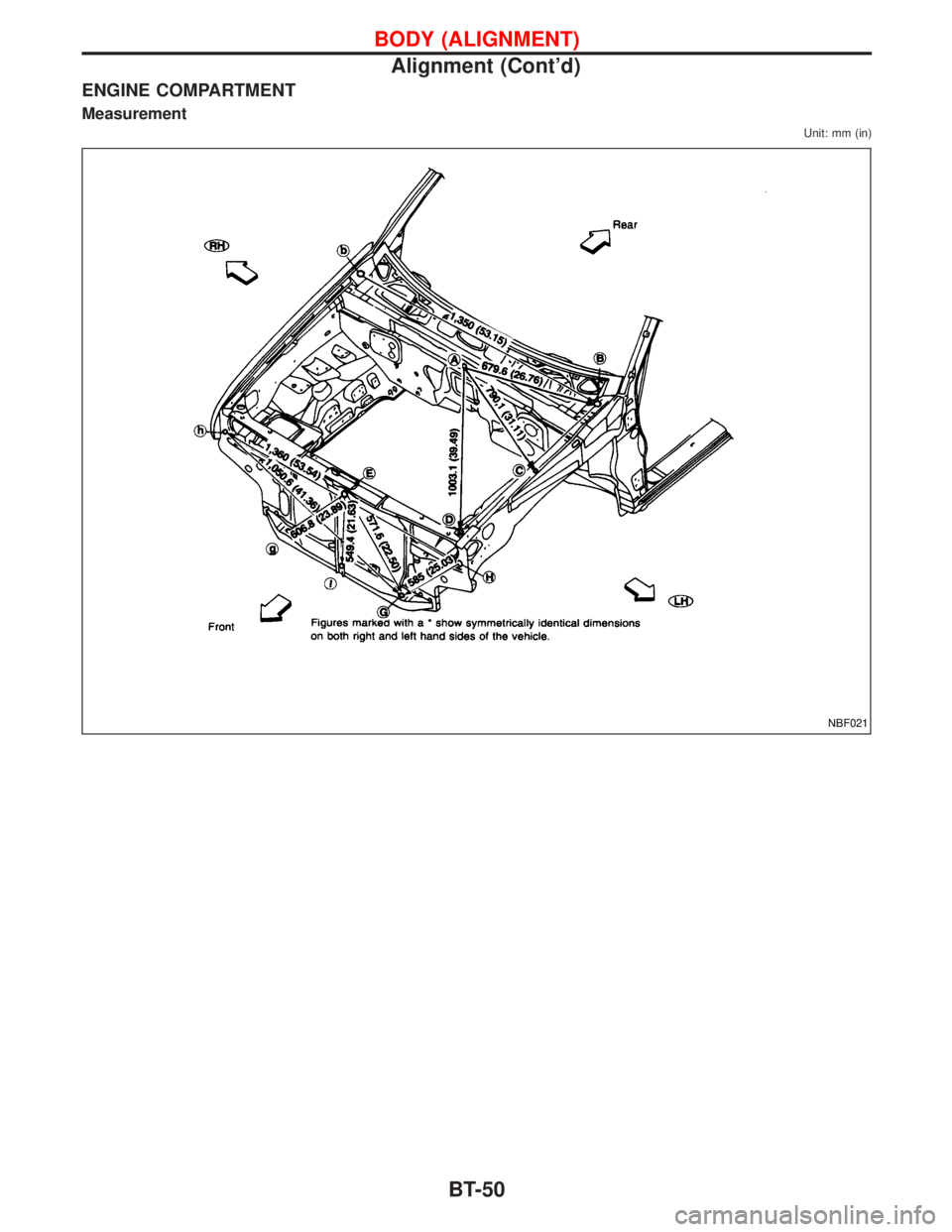
ENGINE COMPARTMENT
Measurement
Unit: mm (in)
NBF021
BODY (ALIGNMENT)
Alignment (Cont'd)
BT-50
Page 339 of 1767
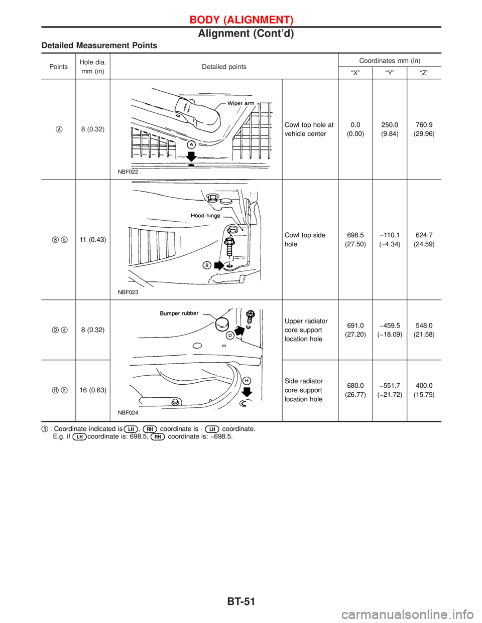
Detailed Measurement Points
PointsHole dia.
mm (in)Detailed pointsCoordinates mm (in)
ªXº ªYº ªZº
q
A8 (0.32)
NBF022
Cowl top hole at
vehicle center0.0
(0.00)250.0
(9.84)760.9
(29.96)
q
Bqb11 (0.43)
NBF023
Cowl top side
hole698.5
(27.50)þ110.1
(þ4.34)624.7
(24.59)
q
Dqd8 (0.32)
NBF024
Upper radiator
core support
location hole691.0
(27.20)þ459.5
(þ18.09)548.0
(21.58)
q
Hqh16 (0.63)Side radiator
core support
location hole680.0
(26.77)þ551.7
(þ21.72)400.0
(15.75)
q
1: Coordinate indicated isLH,RHcoordinate is -LHcoordinate.
E.g. ifLHcoordinate is: 698.5,RHcoordinate is: þ698.5.
BODY (ALIGNMENT)
Alignment (Cont'd)
BT-51
Page 340 of 1767
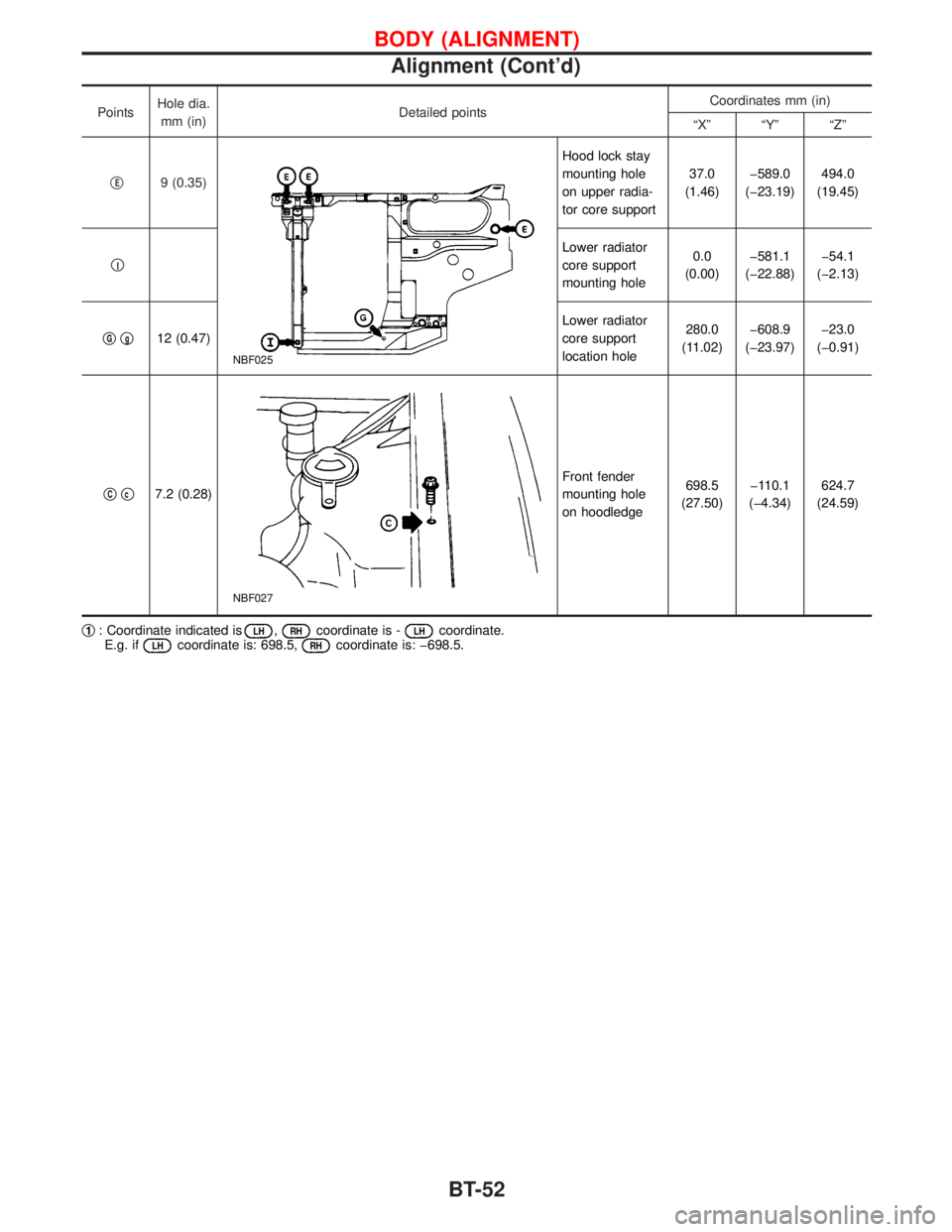
PointsHole dia.
mm (in)Detailed pointsCoordinates mm (in)
ªXº ªYº ªZº
q
E9 (0.35)
NBF025
Hood lock stay
mounting hole
on upper radia-
tor core support37.0
(1.46)þ589.0
(þ23.19)494.0
(19.45)
q
I
Lower radiator
core support
mounting hole0.0
(0.00)þ581.1
(þ22.88)þ54.1
(þ2.13)
q
Gqg12 (0.47)Lower radiator
core support
location hole280.0
(11.02)þ608.9
(þ23.97)þ23.0
(þ0.91)
q
Cqc7.2 (0.28)
NBF027
Front fender
mounting hole
on hoodledge698.5
(27.50)þ110.1
(þ4.34)624.7
(24.59)
q
1: Coordinate indicated isLH,RHcoordinate is -LHcoordinate.
E.g. ifLHcoordinate is: 698.5,RHcoordinate is: þ698.5.
BODY (ALIGNMENT)
Alignment (Cont'd)
BT-52
Trending: maintenance schedule, manual transmission, change wheel, remove seats, charging, key battery, interior lights
