NISSAN TERRANO 2002 Service Repair Manual
TERRANO 2002
NISSAN
NISSAN
https://www.carmanualsonline.info/img/5/57393/w960_57393-0.png
NISSAN TERRANO 2002 Service Repair Manual
Trending: AUX, alternator replacement, heating, key battery, fuel consumption, coolant reservoir, automatic transmission
Page 371 of 1767
Precautions
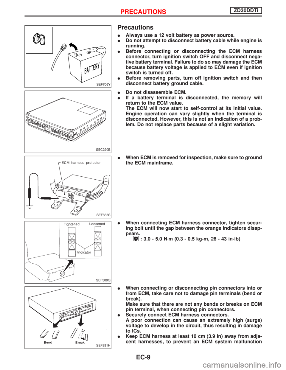
IAlways use a 12 volt battery as power source.
IDo not attempt to disconnect battery cable while engine is
running.
IBefore connecting or disconnecting the ECM harness
connector, turn ignition switch OFF and disconnect nega-
tive battery terminal. Failure to do so may damage the ECM
because battery voltage is applied to ECM even if ignition
switch is turned off.
IBefore removing parts, turn off ignition switch and then
disconnect battery ground cable.
IDo not disassemble ECM.
IIf a battery terminal is disconnected, the memory will
return to the ECM value.
The ECM will now start to self-control at its initial value.
Engine operation can vary slightly when the terminal is
disconnected. However, this is not an indication of a prob-
lem. Do not replace parts because of a slight variation.
IWhen ECM is removed for inspection, make sure to ground
the ECM mainframe.
IWhen connecting ECM harness connector, tighten secur-
ing bolt until the gap between the orange indicators disap-
pears.
: 3.0 - 5.0 N×m (0.3 - 0.5 kg-m, 26 - 43 in-lb)
IWhen connecting or disconnecting pin connectors into or
from ECM, take care not to damage pin terminals (bend or
break).
Make sure that there are not any bends or breaks on ECM
pin terminal, when connecting pin connectors.
ISecurely connect ECM harness connectors.
A poor connection can cause an extremely high (surge)
voltage to develop in the circuit, thus resulting in damage
to ICs.
IKeep ECM harness at least 10 cm (3.9 in) away from adja-
cent harnesses, to prevent an ECM system malfunction
SEF706Y
SEC220B
SEF665S
SEF308Q
SEF291H
PRECAUTIONSZD30DDTi
EC-9
Page 372 of 1767
due to receiving external noise, degraded operation of ICs,
etc.
IKeep ECM parts and harnesses dry.
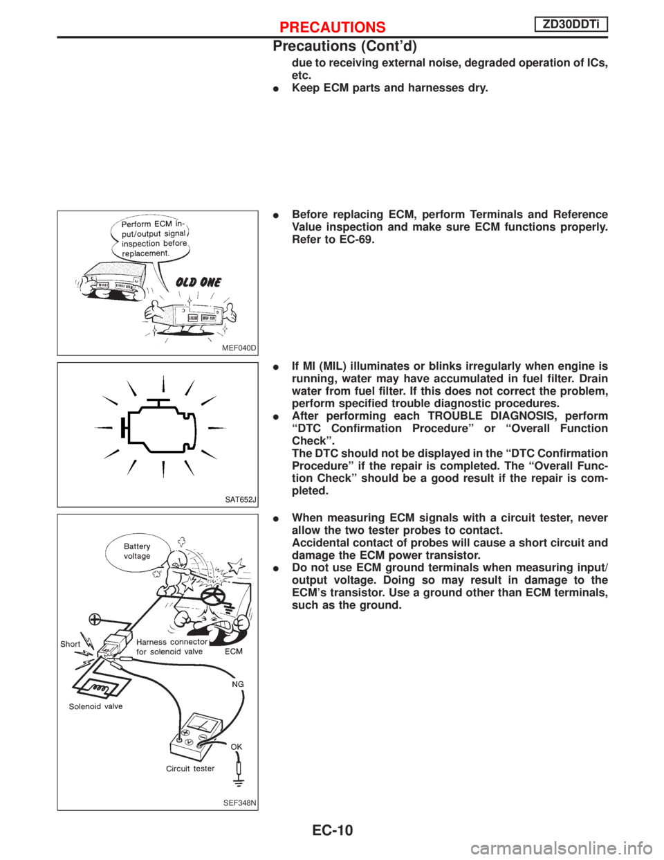
IBefore replacing ECM, perform Terminals and Reference
Value inspection and make sure ECM functions properly.
Refer to EC-69.
IIf MI (MIL) illuminates or blinks irregularly when engine is
running, water may have accumulated in fuel filter. Drain
water from fuel filter. If this does not correct the problem,
perform specified trouble diagnostic procedures.
IAfter performing each TROUBLE DIAGNOSIS, perform
ªDTC Confirmation Procedureº or ªOverall Function
Checkº.
The DTC should not be displayed in the ªDTC Confirmation
Procedureº if the repair is completed. The ªOverall Func-
tion Checkº should be a good result if the repair is com-
pleted.
IWhen measuring ECM signals with a circuit tester, never
allow the two tester probes to contact.
Accidental contact of probes will cause a short circuit and
damage the ECM power transistor.
IDo not use ECM ground terminals when measuring input/
output voltage. Doing so may result in damage to the
ECM's transistor. Use a ground other than ECM terminals,
such as the ground.
MEF040D
SAT652J
SEF348N
PRECAUTIONSZD30DDTi
Precautions (Cont'd)
EC-10
Page 373 of 1767
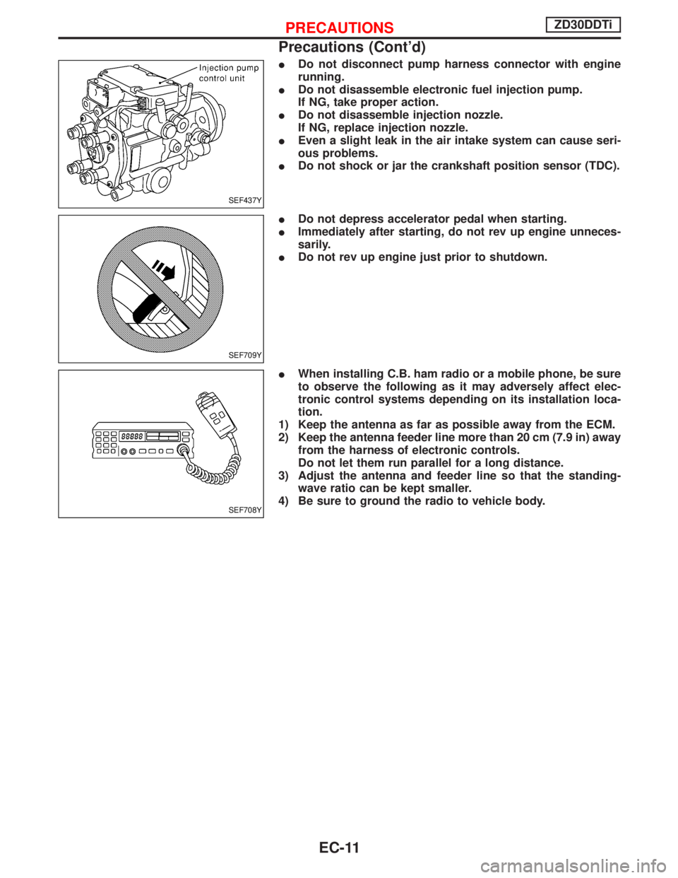
IDo not disconnect pump harness connector with engine
running.
IDo not disassemble electronic fuel injection pump.
If NG, take proper action.
IDo not disassemble injection nozzle.
If NG, replace injection nozzle.
IEven a slight leak in the air intake system can cause seri-
ous problems.
IDo not shock or jar the crankshaft position sensor (TDC).
IDo not depress accelerator pedal when starting.
IImmediately after starting, do not rev up engine unneces-
sarily.
IDo not rev up engine just prior to shutdown.
IWhen installing C.B. ham radio or a mobile phone, be sure
to observe the following as it may adversely affect elec-
tronic control systems depending on its installation loca-
tion.
1) Keep the antenna as far as possible away from the ECM.
2) Keep the antenna feeder line more than 20 cm (7.9 in) away
from the harness of electronic controls.
Do not let them run parallel for a long distance.
3) Adjust the antenna and feeder line so that the standing-
wave ratio can be kept smaller.
4) Be sure to ground the radio to vehicle body.
SEF437Y
SEF709Y
SEF708Y
PRECAUTIONSZD30DDTi
Precautions (Cont'd)
EC-11
Page 374 of 1767
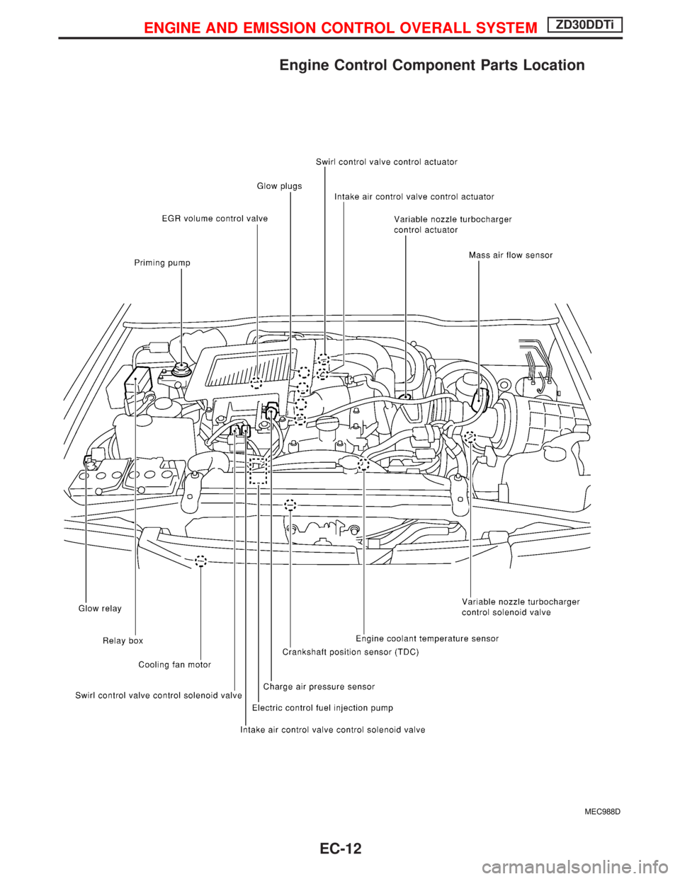
Engine Control Component Parts Location
MEC988D
ENGINE AND EMISSION CONTROL OVERALL SYSTEMZD30DDTi
EC-12
Page 375 of 1767
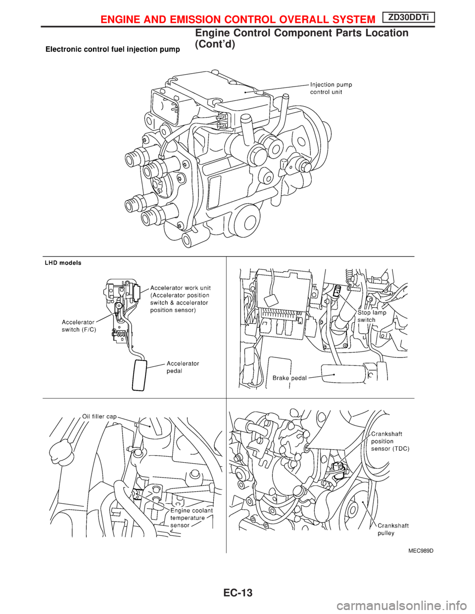
MEC989D
ENGINE AND EMISSION CONTROL OVERALL SYSTEMZD30DDTi
Engine Control Component Parts Location
(Cont'd)
EC-13
Page 376 of 1767
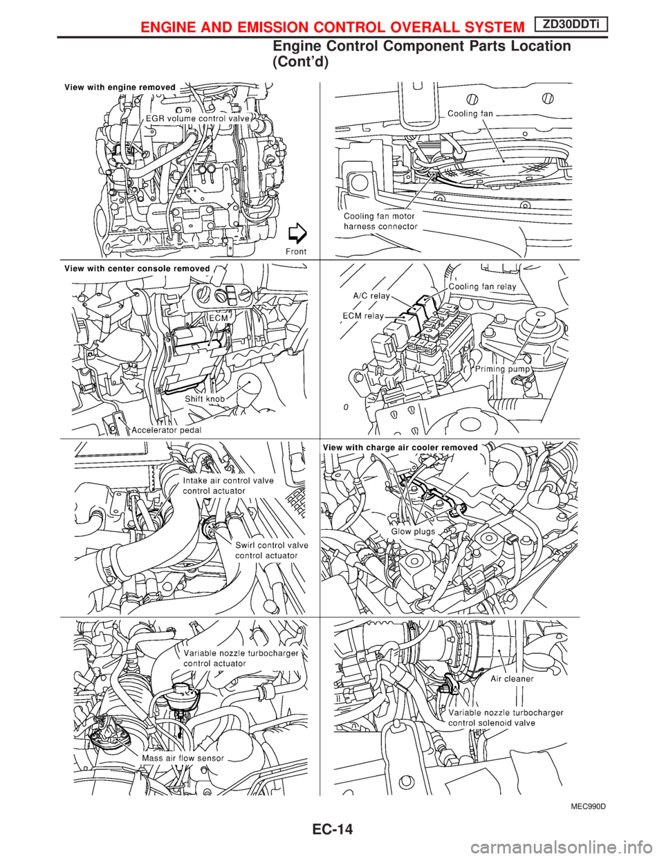
MEC990D
ENGINE AND EMISSION CONTROL OVERALL SYSTEMZD30DDTi
Engine Control Component Parts Location
(Cont'd)
EC-14
Page 377 of 1767
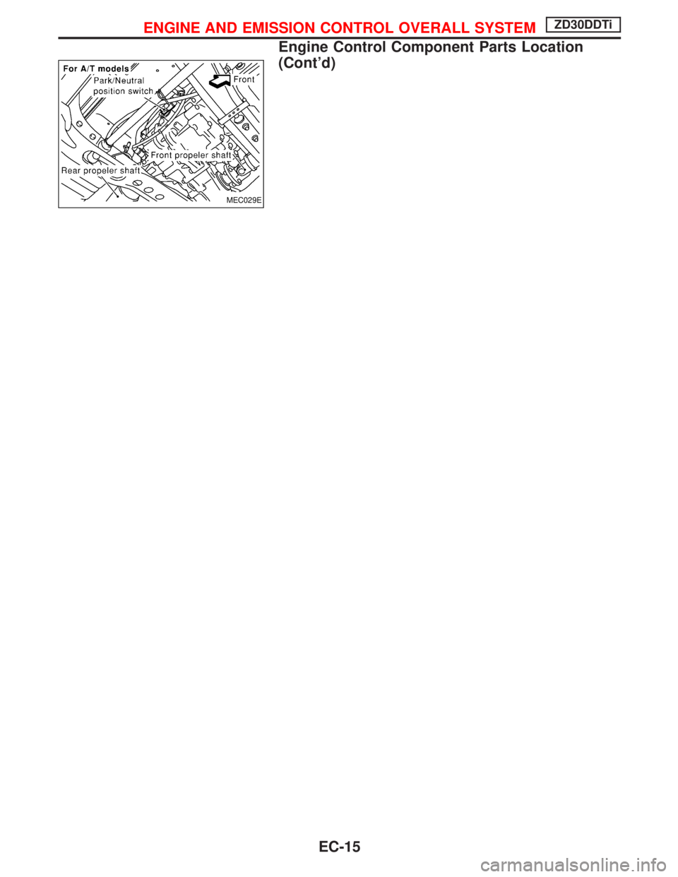
MEC029E
ENGINE AND EMISSION CONTROL OVERALL SYSTEMZD30DDTi
Engine Control Component Parts Location
(Cont'd)
EC-15
Page 378 of 1767
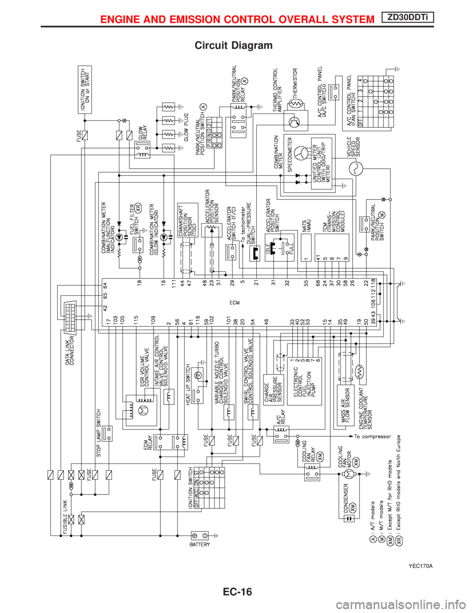
Circuit Diagram
YEC170A
ENGINE AND EMISSION CONTROL OVERALL SYSTEMZD30DDTi
EC-16
Page 379 of 1767
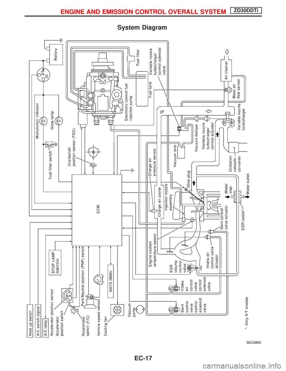
System Diagram
SEC390D
ENGINE AND EMISSION CONTROL OVERALL SYSTEMZD30DDTi
EC-17
Page 380 of 1767
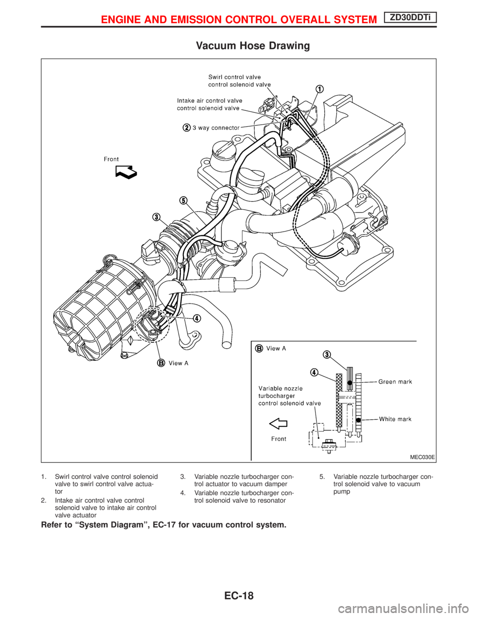
Vacuum Hose Drawing
1. Swirl control valve control solenoid
valve to swirl control valve actua-
tor
2. Intake air control valve control
solenoid valve to intake air control
valve actuator3. Variable nozzle turbocharger con-
trol actuator to vacuum damper
4. Variable nozzle turbocharger con-
trol solenoid valve to resonator5. Variable nozzle turbocharger con-
trol solenoid valve to vacuum
pump
Refer to ªSystem Diagramº, EC-17 for vacuum control system.
MEC030E
ENGINE AND EMISSION CONTROL OVERALL SYSTEMZD30DDTi
EC-18
Trending: audio, jump cable, ground clearance, radiator, Oil grade, alternator, load capacity


