NISSAN TERRANO 2004 Service Repair Manual
Manufacturer: NISSAN, Model Year: 2004, Model line: TERRANO, Model: NISSAN TERRANO 2004Pages: 1833, PDF Size: 53.42 MB
Page 131 of 1833
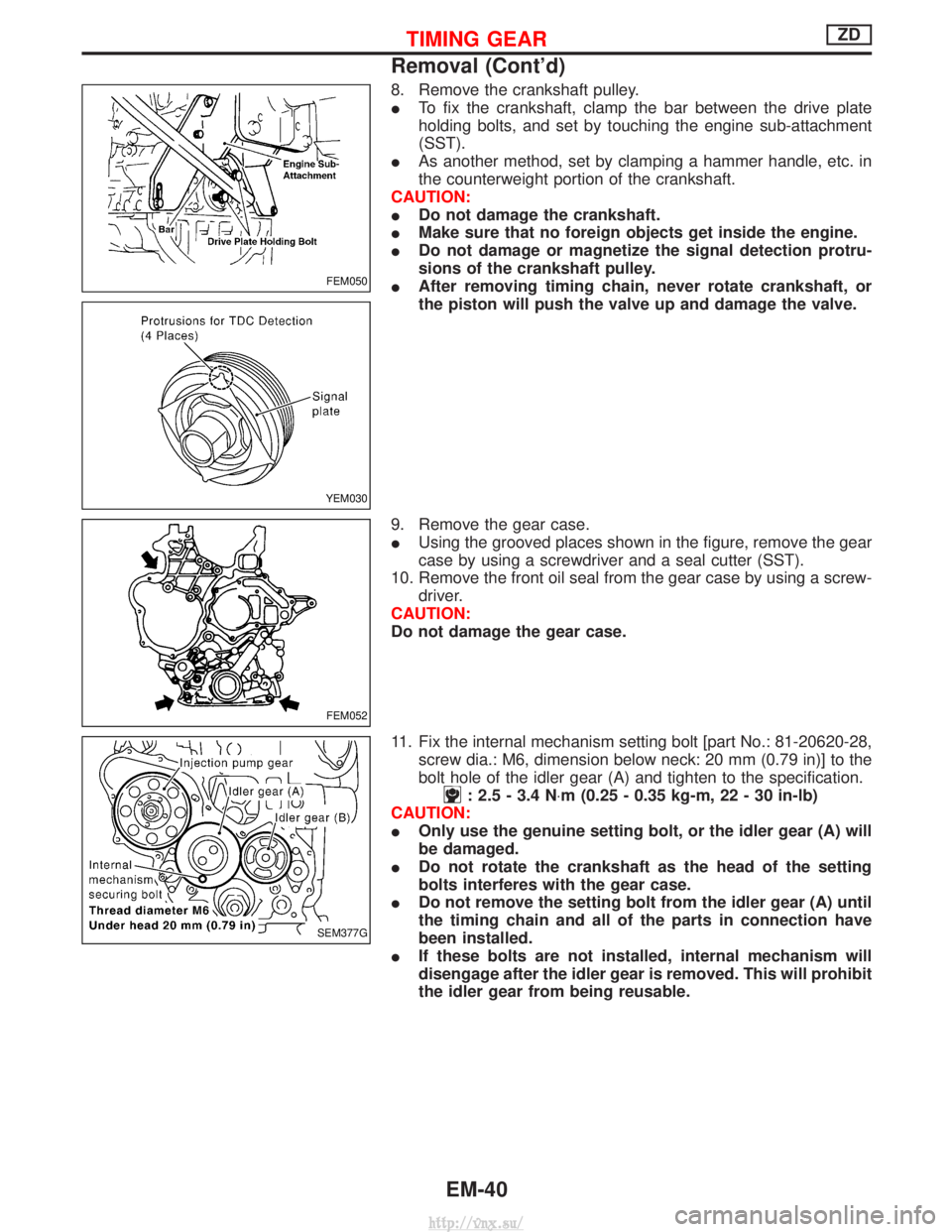
8. Remove the crankshaft pulley.
ITo fix the crankshaft, clamp the bar between the drive plate
holding bolts, and set by touching the engine sub-attachment
(SST).
I As another method, set by clamping a hammer handle, etc. in
the counterweight portion of the crankshaft.
CAUTION:
I Do not damage the crankshaft.
I Make sure that no foreign objects get inside the engine.
I Do not damage or magnetize the signal detection protru-
sions of the crankshaft pulley.
I After removing timing chain, never rotate crankshaft, or
the piston will push the valve up and damage the valve.
9. Remove the gear case.
I Using the grooved places shown in the figure, remove the gear
case by using a screwdriver and a seal cutter (SST).
10. Remove the front oil seal from the gear case by using a screw- driver.
CAUTION:
Do not damage the gear case.
11. Fix the internal mechanism setting bolt [part No.: 81-20620-28, screw dia.: M6, dimension below neck: 20 mm (0.79 in)] to the
bolt hole of the idler gear (A) and tighten to the specification.
: 2.5 - 3.4 N ×m (0.25 - 0.35 kg-m, 22 - 30 in-lb)
CAUTION:
I Only use the genuine setting bolt, or the idler gear (A) will
be damaged.
I Do not rotate the crankshaft as the head of the setting
bolts interferes with the gear case.
I Do not remove the setting bolt from the idler gear (A) until
the timing chain and all of the parts in connection have
been installed.
I If these bolts are not installed, internal mechanism will
disengage after the idler gear is removed. This will prohibit
the idler gear from being reusable.
FEM050
YEM030
FEM052
SEM377G
TIMING GEARZD
Removal (Cont'd)
EM-40
http://vnx.su/
Page 132 of 1833
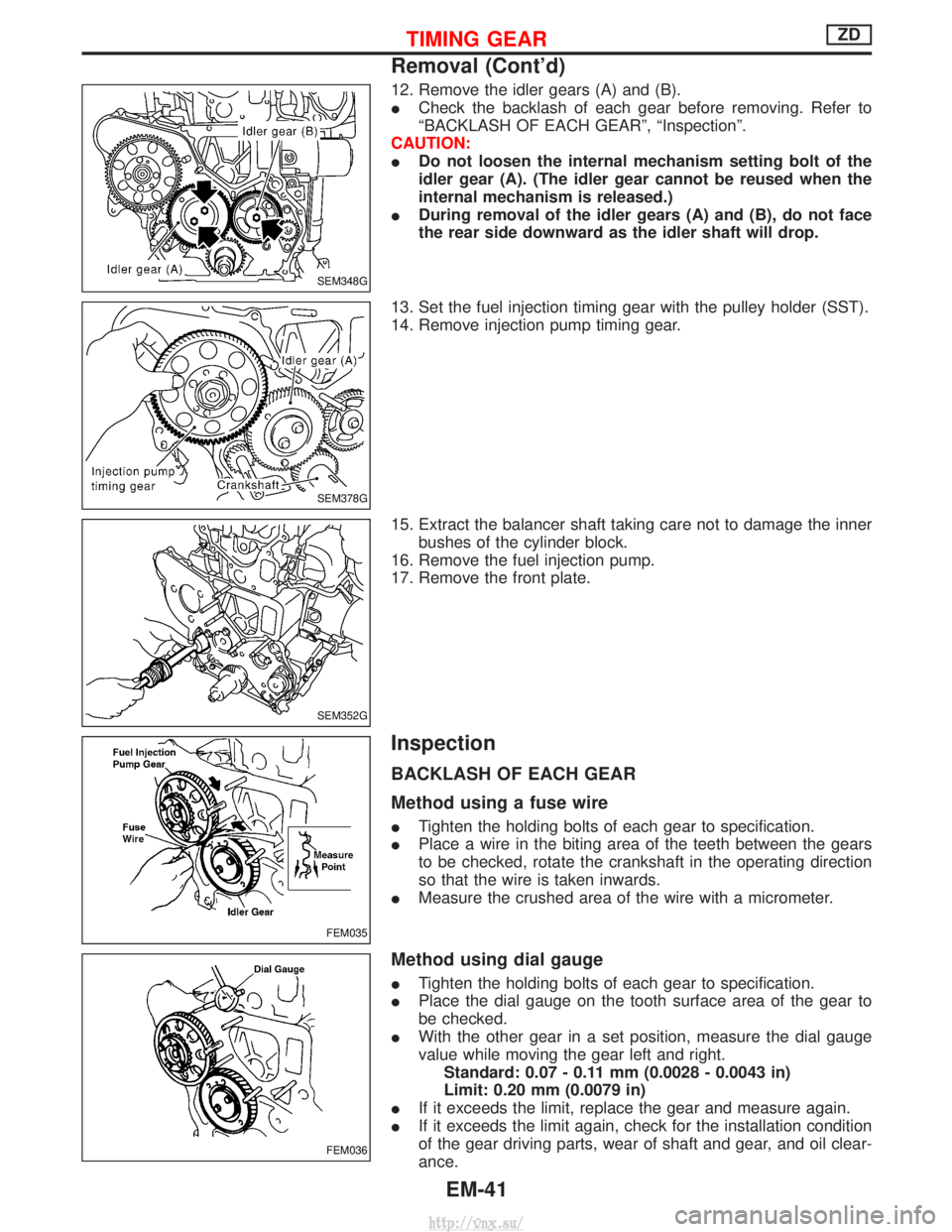
12. Remove the idler gears (A) and (B).
ICheck the backlash of each gear before removing. Refer to
ªBACKLASH OF EACH GEARº, ªInspectionº.
CAUTION:
I Do not loosen the internal mechanism setting bolt of the
idler gear (A). (The idler gear cannot be reused when the
internal mechanism is released.)
I During removal of the idler gears (A) and (B), do not face
the rear side downward as the idler shaft will drop.
13. Set the fuel injection timing gear with the pulley holder (SST).
14. Remove injection pump timing gear.
15. Extract the balancer shaft taking care not to damage the inner bushes of the cylinder block.
16. Remove the fuel injection pump.
17. Remove the front plate.
Inspection
BACKLASH OF EACH GEAR
Method using a fuse wire
I Tighten the holding bolts of each gear to specification.
I Place a wire in the biting area of the teeth between the gears
to be checked, rotate the crankshaft in the operating direction
so that the wire is taken inwards.
I Measure the crushed area of the wire with a micrometer.
Method using dial gauge
ITighten the holding bolts of each gear to specification.
I Place the dial gauge on the tooth surface area of the gear to
be checked.
I With the other gear in a set position, measure the dial gauge
value while moving the gear left and right.
Standard: 0.07 - 0.11 mm (0.0028 - 0.0043 in)
Limit: 0.20 mm (0.0079 in)
I If it exceeds the limit, replace the gear and measure again.
I If it exceeds the limit again, check for the installation condition
of the gear driving parts, wear of shaft and gear, and oil clear-
ance.
SEM348G
SEM378G
SEM352G
FEM035
FEM036
TIMING GEARZD
Removal (Cont'd)
EM-41
http://vnx.su/
Page 133 of 1833
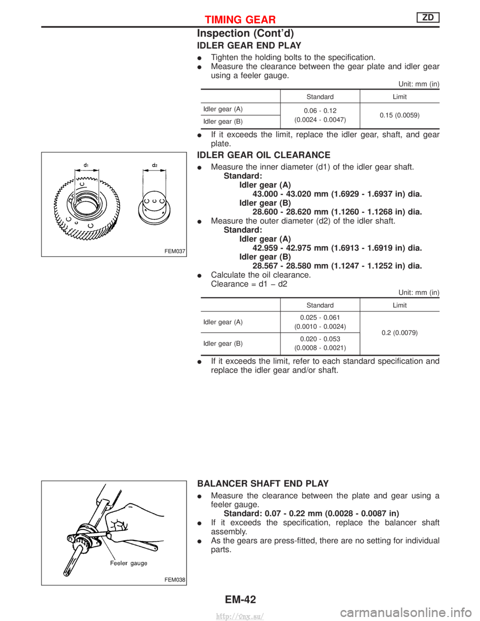
IDLER GEAR END PLAY
ITighten the holding bolts to the specification.
I Measure the clearance between the gear plate and idler gear
using a feeler gauge.
Unit: mm (in)
Standard Limit
Idler gear (A) 0.06 - 0.12
(0.0024 - 0.0047) 0.15 (0.0059)
Idler gear (B)
I If it exceeds the limit, replace the idler gear, shaft, and gear
plate.
IDLER GEAR OIL CLEARANCE
IMeasure the inner diameter (d1) of the idler gear shaft.
Standard: Idler gear (A)43.000 - 43.020 mm (1.6929 - 1.6937 in) dia.
Idler gear (B) 28.600 - 28.620 mm (1.1260 - 1.1268 in) dia.
I Measure the outer diameter (d2) of the idler shaft.
Standard: Idler gear (A)42.959 - 42.975 mm (1.6913 - 1.6919 in) dia.
Idler gear (B) 28.567 - 28.580 mm (1.1247 - 1.1252 in) dia.
I Calculate the oil clearance.
Clearance = d1 þ d2
Unit: mm (in)
Standard Limit
Idler gear (A) 0.025 - 0.061
(0.0010 - 0.0024) 0.2 (0.0079)
Idler gear (B) 0.020 - 0.053
(0.0008 - 0.0021)
I If it exceeds the limit, refer to each standard specification and
replace the idler gear and/or shaft.
BALANCER SHAFT END PLAY
IMeasure the clearance between the plate and gear using a
feeler gauge.
Standard: 0.07 - 0.22 mm (0.0028 - 0.0087 in)
I If it exceeds the specification, replace the balancer shaft
assembly.
I As the gears are press-fitted, there are no setting for individual
parts.
FEM037
FEM038
TIMING GEARZD
Inspection (Cont'd)
EM-42
http://vnx.su/
Page 134 of 1833
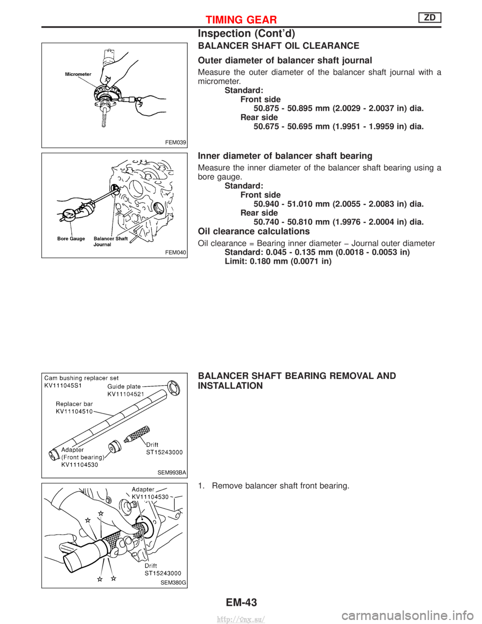
BALANCER SHAFT OIL CLEARANCE
Outer diameter of balancer shaft journal
Measure the outer diameter of the balancer shaft journal with a
micrometer.Standard:Front side50.875 - 50.895 mm (2.0029 - 2.0037 in) dia.
Rear side 50.675 - 50.695 mm (1.9951 - 1.9959 in) dia.
Inner diameter of balancer shaft bearing
Measure the inner diameter of the balancer shaft bearing using a
bore gauge. Standard:Front side50.940 - 51.010 mm (2.0055 - 2.0083 in) dia.
Rear side 50.740 - 50.810 mm (1.9976 - 2.0004 in) dia.
Oil clearance calculations
Oil clearance = Bearing inner diameter þ Journal outer diameter Standard: 0.045 - 0.135 mm (0.0018 - 0.0053 in)
Limit: 0.180 mm (0.0071 in)
BALANCER SHAFT BEARING REMOVAL AND
INSTALLATION
1. Remove balancer shaft front bearing.
FEM039
FEM040
SEM993BA
SEM380G
TIMING GEARZD
Inspection (Cont'd)
EM-43
http://vnx.su/
Page 135 of 1833
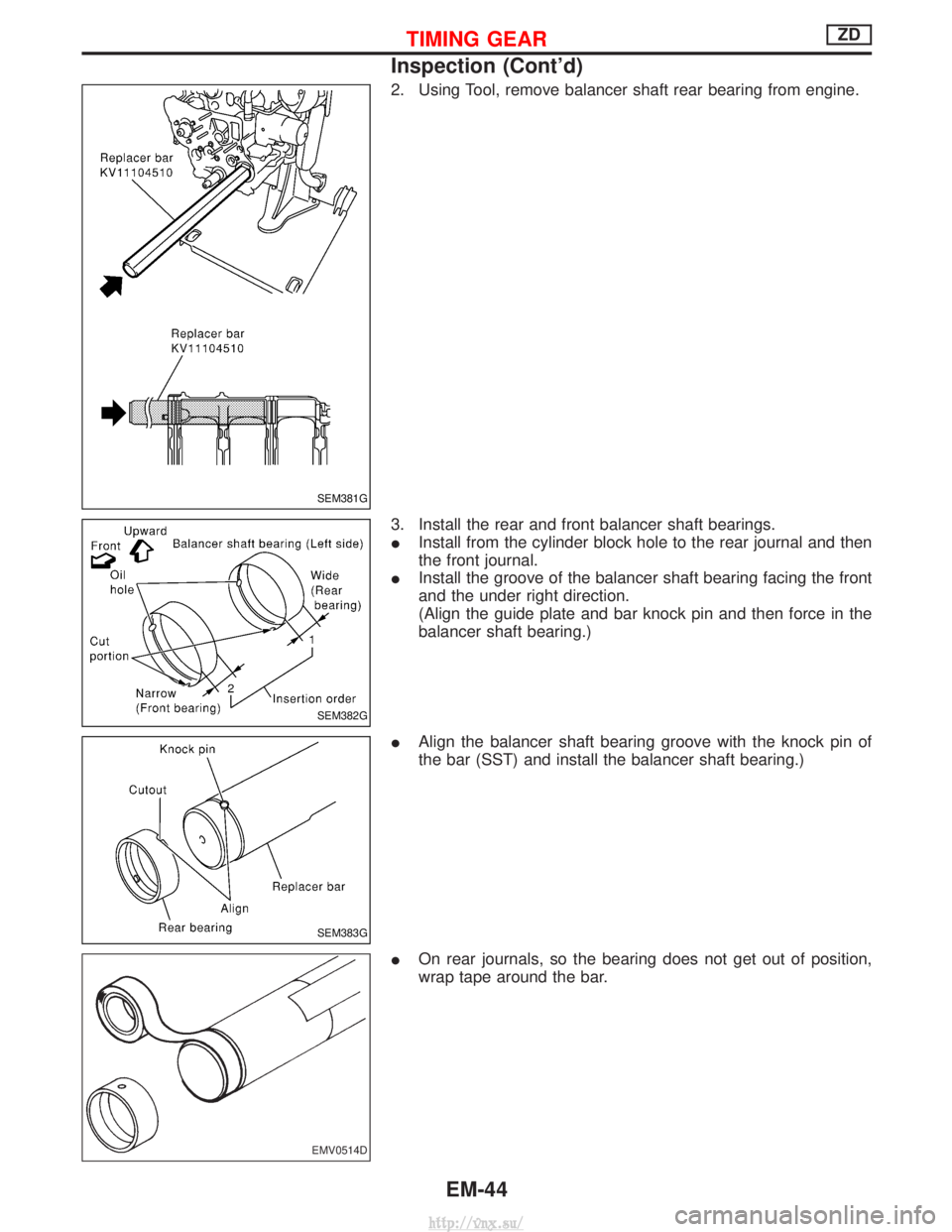
2. Using Tool, remove balancer shaft rear bearing from engine.
3. Install the rear and front balancer shaft bearings.
IInstall from the cylinder block hole to the rear journal and then
the front journal.
I Install the groove of the balancer shaft bearing facing the front
and the under right direction.
(Align the guide plate and bar knock pin and then force in the
balancer shaft bearing.)
I Align the balancer shaft bearing groove with the knock pin of
the bar (SST) and install the balancer shaft bearing.)
I On rear journals, so the bearing does not get out of position,
wrap tape around the bar.
SEM381G
SEM382G
SEM383G
EMV0514D
TIMING GEARZD
Inspection (Cont'd)
EM-44
http://vnx.su/
Page 136 of 1833
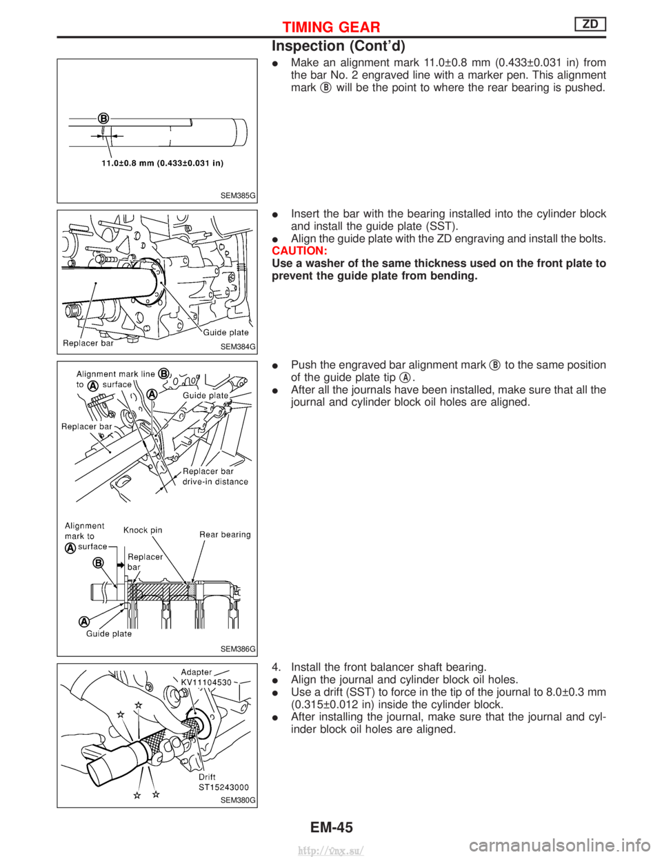
IMake an alignment mark 11.0 0.8 mm (0.433 0.031 in) from
the bar No. 2 engraved line with a marker pen. This alignment
mark q
Bwill be the point to where the rear bearing is pushed.
I Insert the bar with the bearing installed into the cylinder block
and install the guide plate (SST).
I Align the guide plate with the ZD engraving and install the bolts.
CAUTION:
Use a washer of the same thickness used on the front plate to
prevent the guide plate from bending.
I Push the engraved bar alignment mark q
Bto the same position
of the guide plate tip q
A.
I After all the journals have been installed, make sure that all the
journal and cylinder block oil holes are aligned.
4. Install the front balancer shaft bearing.
I Align the journal and cylinder block oil holes.
I Use a drift (SST) to force in the tip of the journal to 8.0 0.3 mm
(0.315 0.012 in) inside the cylinder block.
I After installing the journal, make sure that the journal and cyl-
inder block oil holes are aligned.
SEM385G
SEM384G
SEM386G
SEM380G
TIMING GEARZD
Inspection (Cont'd)
EM-45
http://vnx.su/
Page 137 of 1833
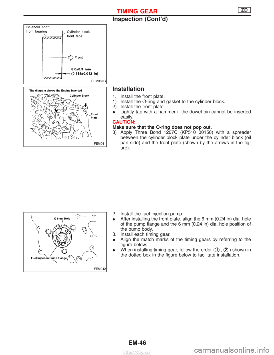
Installation
1. Install the front plate.
1) Install the O-ring and gasket to the cylinder block.
2) Install the front plate.
ILightly tap with a hammer if the dowel pin cannot be inserted
easily.
CAUTION:
Make sure that the O-ring does not pop out.
3) Apply Three Bond 1207C (KP510 00150) with a spreader between the cylinder block plate under the cylinder block (oil
pan side) and the front plate (shown by the arrows in the fig-
ure).
2. Install the fuel injection pump.
I After installing the front plate, align the 6 mm (0.24 in) dia. hole
of the pump flange and the 6 mm (0.24 in) dia. hole position of
the pump body.
3. Install each timing gear.
I Align the match marks of the timing gears by referring to the
figure below.
I When installing timing gear, follow the order ( q
1,q2) shown in
the dotted box in the figure below to facilitate installation.
SEM387G
FEM041
FEM042
TIMING GEARZD
Inspection (Cont'd)
EM-46
http://vnx.su/
Page 138 of 1833
![NISSAN TERRANO 2004 Service Repair Manual 4. Install the front oil seal to the gear case.
IApply engine oil to the fitting side.
I Evenly insert the front oil seal using a drift [outer dia.: approx.
64 mm (2.52 in)] completely.
CAUTION:
Make NISSAN TERRANO 2004 Service Repair Manual 4. Install the front oil seal to the gear case.
IApply engine oil to the fitting side.
I Evenly insert the front oil seal using a drift [outer dia.: approx.
64 mm (2.52 in)] completely.
CAUTION:
Make](/img/5/57394/w960_57394-137.png)
4. Install the front oil seal to the gear case.
IApply engine oil to the fitting side.
I Evenly insert the front oil seal using a drift [outer dia.: approx.
64 mm (2.52 in)] completely.
CAUTION:
Make sure the oil seal does not spill off the end side of the gear
case.
5. Install the gear case.
1) Before installing gear case, remove all traces of liquid gasket from mating surface using a scraper.
2) Align gasket with dowel and install.
3) Install the O-rings to the gear case.
I The O-ring at the top position shown in the figure can be
installed in during cylinder head installation.
4) Apply a continuous bead of liquid gasket to gear case.
I Use Genuine Liquid Gasket or equivalent.
a. Coat of liquid gasket should be maintained within 2.0 to 3.0 mm (0.079 to 0.118 in) dia. range.
b. Attach gear case to cylinder block within 5 minutes after coating.
c. Wait at least 30 minutes before refilling engine oil or start- ing engine.
FEM043
FEM044
SEM353G
FEM045
TIMING GEARZD
Installation (Cont'd)
EM-47
http://vnx.su/
Page 139 of 1833
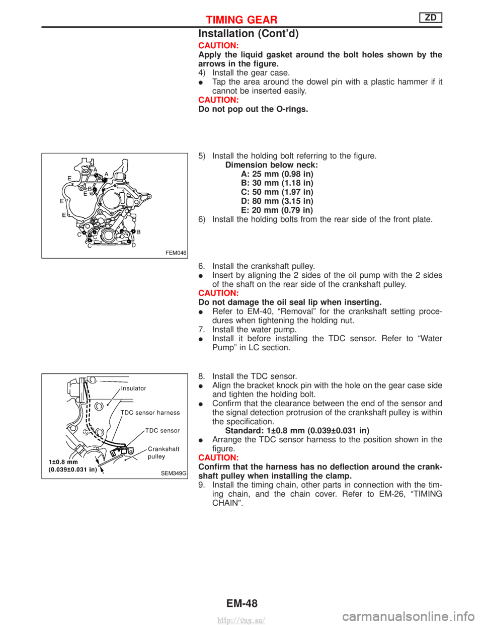
CAUTION:
Apply the liquid gasket around the bolt holes shown by the
arrows in the figure.
4) Install the gear case.
ITap the area around the dowel pin with a plastic hammer if it
cannot be inserted easily.
CAUTION:
Do not pop out the O-rings.
5) Install the holding bolt referring to the figure. Dimension below neck:A: 25 mm (0.98 in)
B: 30 mm (1.18 in)
C: 50 mm (1.97 in)
D: 80 mm (3.15 in)
E: 20 mm (0.79 in)
6) Install the holding bolts from the rear side of the front plate.
6. Install the crankshaft pulley.
I Insert by aligning the 2 sides of the oil pump with the 2 sides
of the shaft on the rear side of the crankshaft pulley.
CAUTION:
Do not damage the oil seal lip when inserting.
I Refer to EM-40, ªRemovalº for the crankshaft setting proce-
dures when tightening the holding nut.
7. Install the water pump.
I Install it before installing the TDC sensor. Refer to ªWater
Pumpº in LC section.
8. Install the TDC sensor.
I Align the bracket knock pin with the hole on the gear case side
and tighten the holding bolt.
I Confirm that the clearance between the end of the sensor and
the signal detection protrusion of the crankshaft pulley is within
the specification.
Standard: 1 0.8 mm (0.039 0.031 in)
I Arrange the TDC sensor harness to the position shown in the
figure.
CAUTION:
Confirm that the harness has no deflection around the crank-
shaft pulley when installing the clamp.
9. Install the timing chain, other parts in connection with the tim- ing chain, and the chain cover. Refer to EM-26, ªTIMING
CHAINº.
FEM046
SEM349G
TIMING GEARZD
Installation (Cont'd)
EM-48
http://vnx.su/
Page 140 of 1833
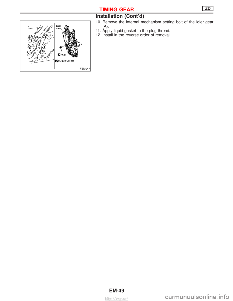
10. Remove the internal mechanism setting bolt of the idler gear(A).
11. Apply liquid gasket to the plug thread.
12. Install in the reverse order of removal.
FEM047
TIMING GEARZD
Installation (Cont'd)
EM-49
http://vnx.su/