NISSAN TERRANO 2004 Service Repair Manual
Manufacturer: NISSAN, Model Year: 2004, Model line: TERRANO, Model: NISSAN TERRANO 2004Pages: 1833, PDF Size: 53.42 MB
Page 151 of 1833
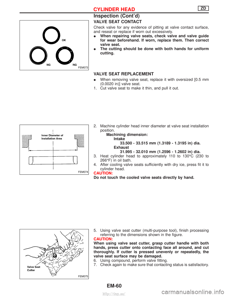
VALVE SEAT CONTACT
Check valve for any evidence of pitting at valve contact surface,
and reseat or replace if worn out excessively.
IWhen repairing valve seats, check valve and valve guide
for wear beforehand. If worn, replace them. Then correct
valve seat.
I The cutting should be done with both hands for uniform
cutting.
VALVE SEAT REPLACEMENT
IWhen removing valve seat, replace it with oversized [0.5 mm
(0.0020 in)] valve seat.
1. Cut valve seat to make it thin, and pull it out.
2. Machine cylinder head inner diameter at valve seat installation position.Machining dimension: Intake33.500 - 33.515 mm (1.3189 - 1.3195 in) dia.
Exhaust 31.995 - 32.010 mm (1.2596 - 1.2602 in) dia.
3. Heat cylinder head to approximately 110 to 130ÉC (230 to 266ÉF) in oil bath.
4. After cooling valve seats sufficiently with dry ice, press fit it to cylinder head.
CAUTION:
Do not touch the cooled valve seats directly by hand.
5. Using valve seat cutter (multi-purpose tool), finish processing referring to the dimensions shown in the figure.
CAUTION:
When using valve seat cutter, grasp cutter handle with both
hands, press cutter onto contacting face all around, and cut
thoroughly. If cutter is pressed unevenly or repeatedly, the
valve seat surface may be damaged.
6. Using compound, perform valve fitting.
7. Check again to make sure that contacting status is satisfactory.
FEM073
FEM074
FEM075
CYLINDER HEADZD
Inspection (Cont'd)
EM-60
http://vnx.su/
Page 152 of 1833
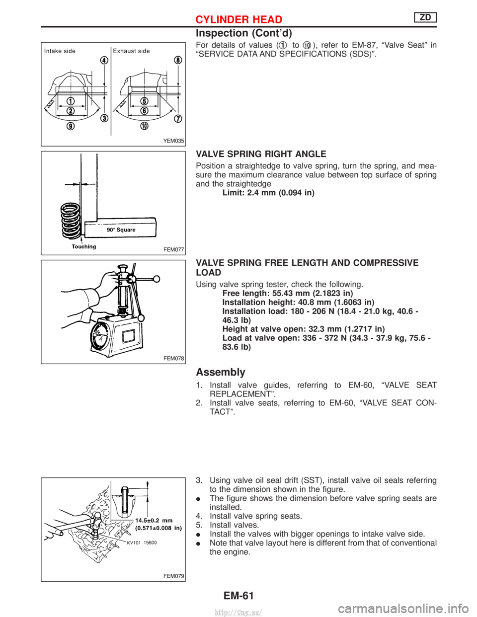
For details of values (q1toq10), refer to EM-87, ªValve Seatº in
ªSERVICE DATA AND SPECIFICATIONS (SDS)º.
VALVE SPRING RIGHT ANGLE
Position a straightedge to valve spring, turn the spring, and mea-
sure the maximum clearance value between top surface of spring
and the straightedge Limit: 2.4 mm (0.094 in)
VALVE SPRING FREE LENGTH AND COMPRESSIVE
LOAD
Using valve spring tester, check the following.Free length: 55.43 mm (2.1823 in)
Installation height: 40.8 mm (1.6063 in)
Installation load: 180 - 206 N (18.4 - 21.0 kg, 40.6 -
46.3 lb)
Height at valve open: 32.3 mm (1.2717 in)
Load at valve open: 336 - 372 N (34.3 - 37.9 kg, 75.6 -
83.6 lb)
Assembly
1. Install valve guides, referring to EM-60, ªVALVE SEATREPLACEMENTº.
2. Install valve seats, referring to EM-60, ªVALVE SEAT CON- TACTº.
3. Using valve oil seal drift (SST), install valve oil seals referring to the dimension shown in the figure.
I The figure shows the dimension before valve spring seats are
installed.
4. Install valve spring seats.
5. Install valves.
I Install the valves with bigger openings to intake valve side.
I Note that valve layout here is different from that of conventional
the engine.
YEM035
FEM077
FEM078
FEM079
CYLINDER HEADZD
Inspection (Cont'd)
EM-61
http://vnx.su/
Page 153 of 1833
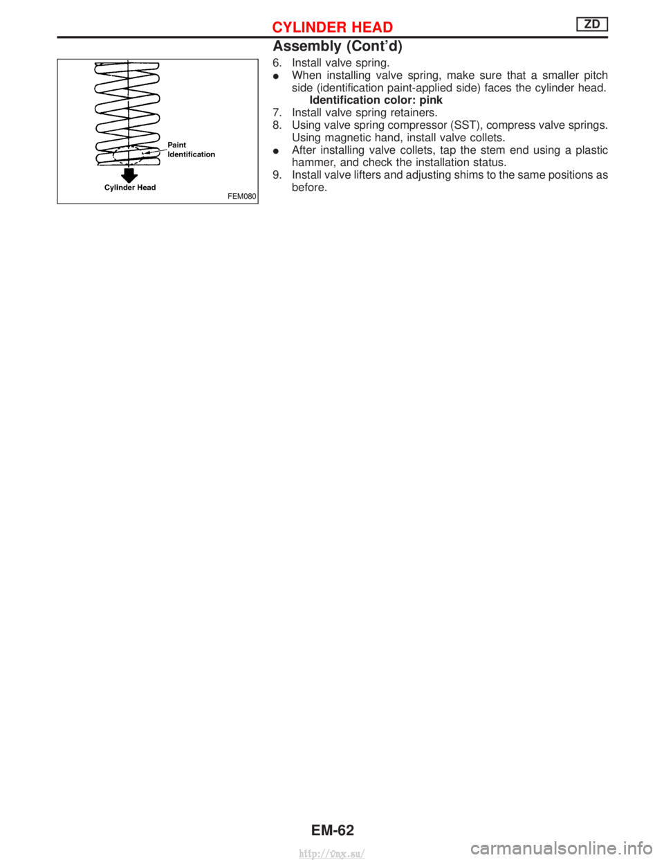
6. Install valve spring.
IWhen installing valve spring, make sure that a smaller pitch
side (identification paint-applied side) faces the cylinder head.
Identification color: pink
7. Install valve spring retainers.
8. Using valve spring compressor (SST), compress valve springs. Using magnetic hand, install valve collets.
I After installing valve collets, tap the stem end using a plastic
hammer, and check the installation status.
9. Install valve lifters and adjusting shims to the same positions as before.
FEM080
CYLINDER HEADZD
Assembly (Cont'd)
EM-62
http://vnx.su/
Page 154 of 1833
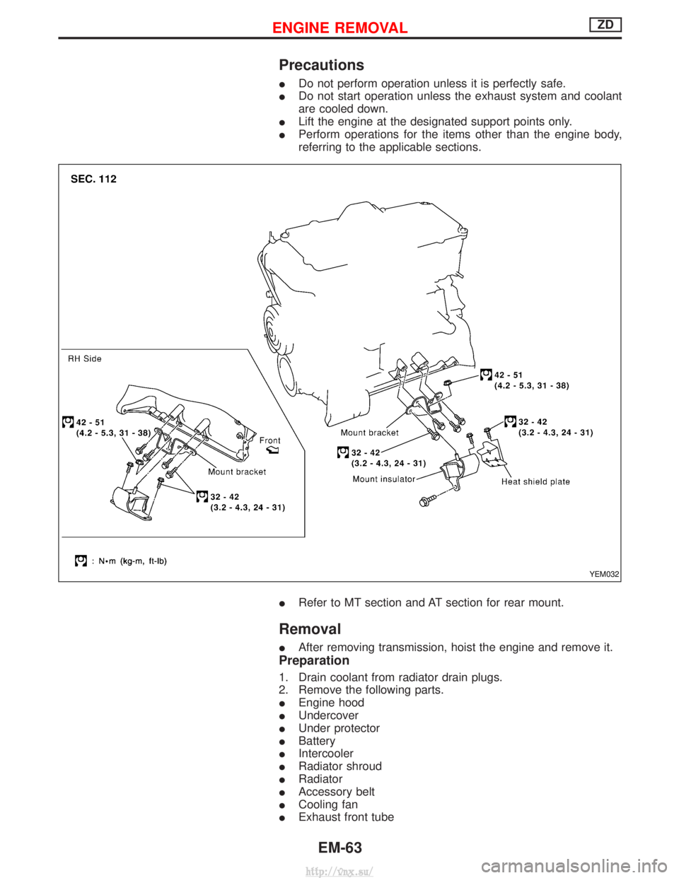
Precautions
IDo not perform operation unless it is perfectly safe.
I Do not start operation unless the exhaust system and coolant
are cooled down.
I Lift the engine at the designated support points only.
I Perform operations for the items other than the engine body,
referring to the applicable sections.
I Refer to MT section and AT section for rear mount.
Removal
IAfter removing transmission, hoist the engine and remove it.
Preparation
1. Drain coolant from radiator drain plugs.
2. Remove the following parts.
IEngine hood
I Undercover
I Under protector
I Battery
I Intercooler
I Radiator shroud
I Radiator
I Accessory belt
I Cooling fan
I Exhaust front tube
YEM032
ENGINE REMOVALZD
EM-63
http://vnx.su/
Page 155 of 1833
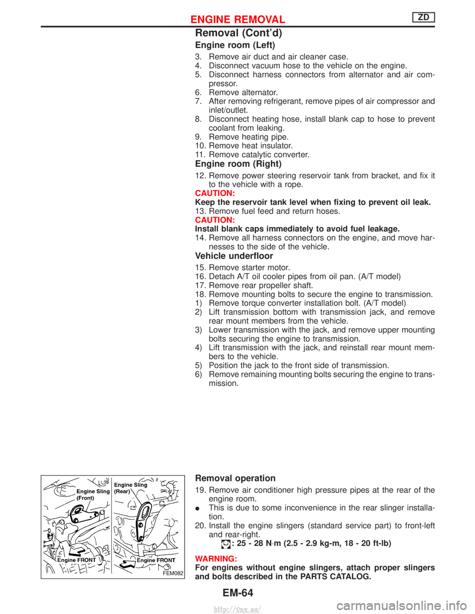
Engine room (Left)
3. Remove air duct and air cleaner case.
4. Disconnect vacuum hose to the vehicle on the engine.
5. Disconnect harness connectors from alternator and air com-pressor.
6. Remove alternator.
7. After removing refrigerant, remove pipes of air compressor and inlet/outlet.
8. Disconnect heating hose, install blank cap to hose to prevent coolant from leaking.
9. Remove heating pipe.
10. Remove heat insulator.
11. Remove catalytic converter.
Engine room (Right)
12. Remove power steering reservoir tank from bracket, and fix it to the vehicle with a rope.
CAUTION:
Keep the reservoir tank level when fixing to prevent oil leak.
13. Remove fuel feed and return hoses.
CAUTION:
Install blank caps immediately to avoid fuel leakage.
14. Remove all harness connectors on the engine, and move har- nesses to the side of the vehicle.
Vehicle underfloor
15. Remove starter motor.
16. Detach A/T oil cooler pipes from oil pan. (A/T model)
17. Remove rear propeller shaft.
18. Remove mounting bolts to secure the engine to transmission.
1) Remove torque converter installation bolt. (A/T model)
2) Lift transmission bottom with transmission jack, and removerear mount members from the vehicle.
3) Lower transmission with the jack, and remove upper mounting bolts securing the engine to transmission.
4) Lift transmission with the jack, and reinstall rear mount mem- bers to the vehicle.
5) Position the jack to the front side of transmission.
6) Remove remaining mounting bolts securing the engine to trans- mission.
Removal operation
19. Remove air conditioner high pressure pipes at the rear of theengine room.
I This is due to some inconvenience in the rear slinger installa-
tion.
20. Install the engine slingers (standard service part) to front-left and rear-right.
:25-28N ×m (2.5 - 2.9 kg-m, 18 - 20 ft-lb)
WARNING:
For engines without engine slingers, attach proper slingers
and bolts described in the PARTS CATALOG.
FEM082
ENGINE REMOVALZD
Removal (Cont'd)
EM-64
http://vnx.su/
Page 156 of 1833
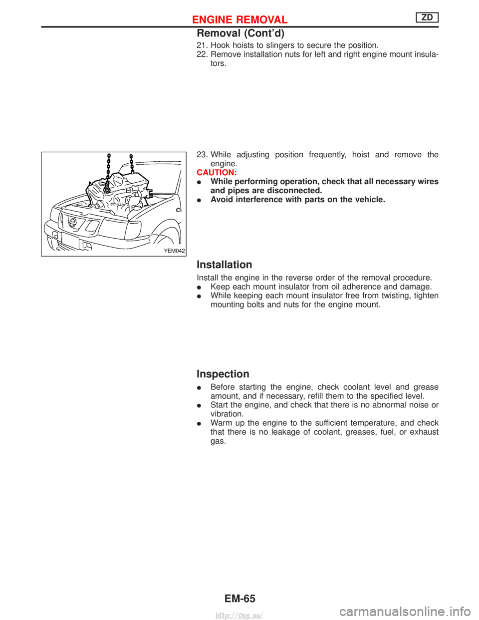
21. Hook hoists to slingers to secure the position.
22. Remove installation nuts for left and right engine mount insula-tors.
23. While adjusting position frequently, hoist and remove the engine.
CAUTION:
I While performing operation, check that all necessary wires
and pipes are disconnected.
I Avoid interference with parts on the vehicle.
Installation
Install the engine in the reverse order of the removal procedure.
IKeep each mount insulator from oil adherence and damage.
I While keeping each mount insulator free from twisting, tighten
mounting bolts and nuts for the engine mount.
Inspection
IBefore starting the engine, check coolant level and grease
amount, and if necessary, refill them to the specified level.
I Start the engine, and check that there is no abnormal noise or
vibration.
I Warm up the engine to the sufficient temperature, and check
that there is no leakage of coolant, greases, fuel, or exhaust
gas.
YEM042
ENGINE REMOVALZD
Removal (Cont'd)
EM-65
http://vnx.su/
Page 157 of 1833
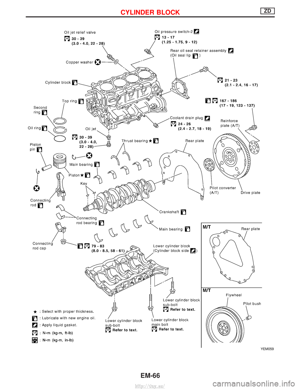
YEM059
CYLINDER BLOCKZD
EM-66
http://vnx.su/
Page 158 of 1833
Selection Procedure for Selective Part
Combination
LocationSelective part combination ItemMethod
Cylinder block - piston Piston and piston assembly
(Part No. is given to a piston and piston pin as a set.) Piston grade (Piston outer
diameter) Refer to ªSelective combination
chartº.
IIdentification grade stamped on each part represents initial
dimension of new part. This grade will not be applied to a
reused part.
I Measure correct dimensions of a reused or modified part, then
refer to ªSelective combination chartº in this manual to identify
the grade.
I Refer to the applicable pages for measurement method for
each part, standards for reuse, and selecting method for selec-
tive part combination.
Disassembly
1. Remove engine assembly from vehicle.
Refer to EM-63, ªENGINE REMOVALº.
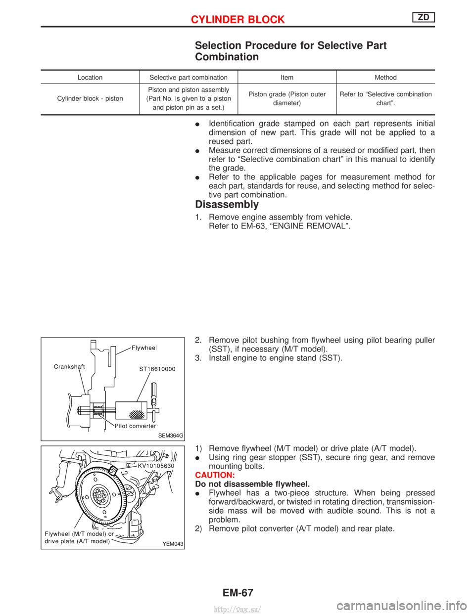
2. Remove pilot bushing from flywheel using pilot bearing puller (SST), if necessary (M/T model).
3. Install engine to engine stand (SST).
1) Remove flywheel (M/T model) or drive plate (A/T model).
I Using ring gear stopper (SST), secure ring gear, and remove
mounting bolts.
CAUTION:
Do not disassemble flywheel.
I Flywheel has a two-piece structure. When being pressed
forward/backward, or twisted in rotating direction, transmission-
side mass will be moved with audible sound. This is not a
problem.
2) Remove pilot converter (A/T model) and rear plate.
SEM364G
YEM043
CYLINDER BLOCKZD
EM-67
http://vnx.su/
Page 159 of 1833
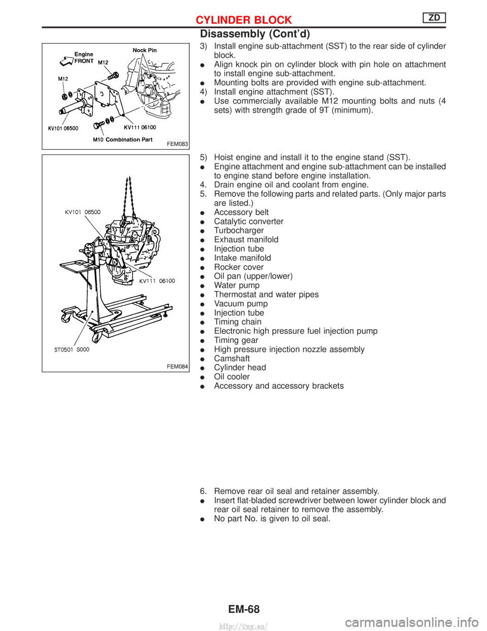
3) Install engine sub-attachment (SST) to the rear side of cylinderblock.
I Align knock pin on cylinder block with pin hole on attachment
to install engine sub-attachment.
I Mounting bolts are provided with engine sub-attachment.
4) Install engine attachment (SST).
I Use commercially available M12 mounting bolts and nuts (4
sets) with strength grade of 9T (minimum).
5) Hoist engine and install it to the engine stand (SST).
I Engine attachment and engine sub-attachment can be installed
to engine stand before engine installation.
4. Drain engine oil and coolant from engine.
5. Remove the following parts and related parts. (Only major parts are listed.)
I Accessory belt
I Catalytic converter
I Turbocharger
I Exhaust manifold
I Injection tube
I Intake manifold
I Rocker cover
I Oil pan (upper/lower)
I Water pump
I Thermostat and water pipes
I Vacuum pump
I Injection tube
I Timing chain
I Electronic high pressure fuel injection pump
I Timing gear
I High pressure injection nozzle assembly
I Camshaft
I Cylinder head
I Oil cooler
I Accessory and accessory brackets
6. Remove rear oil seal and retainer assembly.
I Insert flat-bladed screwdriver between lower cylinder block and
rear oil seal retainer to remove the assembly.
I No part No. is given to oil seal.
FEM083
FEM084
CYLINDER BLOCKZD
Disassembly (Cont'd)
EM-68
http://vnx.su/
Page 160 of 1833
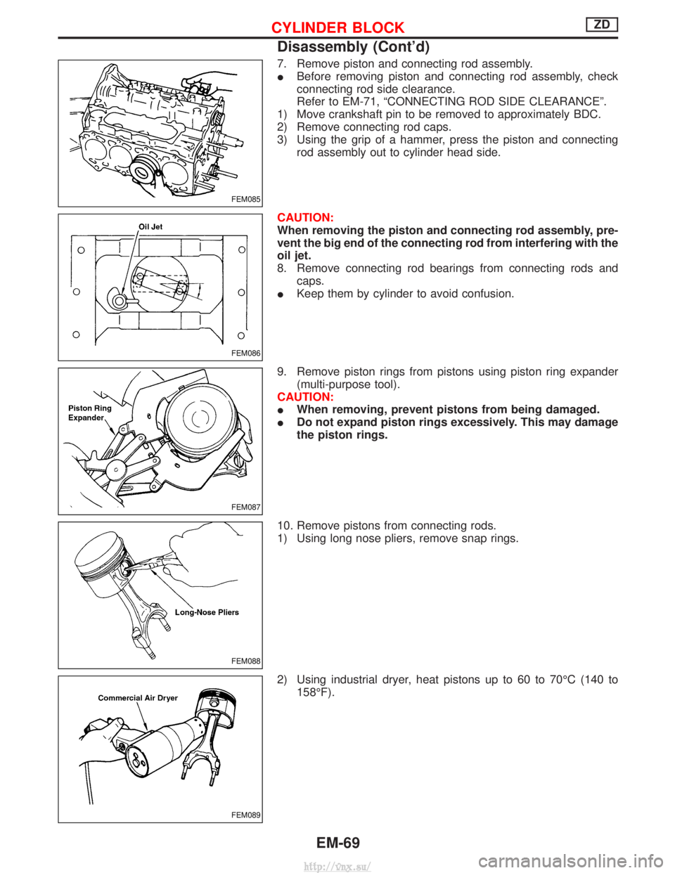
7. Remove piston and connecting rod assembly.
IBefore removing piston and connecting rod assembly, check
connecting rod side clearance.
Refer to EM-71, ªCONNECTING ROD SIDE CLEARANCEº.
1) Move crankshaft pin to be removed to approximately BDC.
2) Remove connecting rod caps.
3) Using the grip of a hammer, press the piston and connecting rod assembly out to cylinder head side.
CAUTION:
When removing the piston and connecting rod assembly, pre-
vent the big end of the connecting rod from interfering with the
oil jet.
8. Remove connecting rod bearings from connecting rods and caps.
I Keep them by cylinder to avoid confusion.
9. Remove piston rings from pistons using piston ring expander (multi-purpose tool).
CAUTION:
I When removing, prevent pistons from being damaged.
I Do not expand piston rings excessively. This may damage
the piston rings.
10. Remove pistons from connecting rods.
1) Using long nose pliers, remove snap rings.
2) Using industrial dryer, heat pistons up to 60 to 70ÉC (140 to 158ÉF).
FEM085
FEM086
FEM087
FEM088
FEM089
CYLINDER BLOCKZD
Disassembly (Cont'd)
EM-69
http://vnx.su/