NISSAN TERRANO 2004 Service Repair Manual
Manufacturer: NISSAN, Model Year: 2004, Model line: TERRANO, Model: NISSAN TERRANO 2004Pages: 1833, PDF Size: 53.42 MB
Page 1461 of 1833
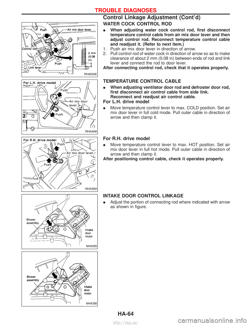
WATER COCK CONTROL ROD
IWhen adjusting water cock control rod, first disconnect
temperature control cable from air mix door lever and then
adjust control rod. Reconnect temperature control cable
and readjust it. (Refer to next item.)
1. Push air mix door lever in direction of arrow.
2. Pull control rod of water cock in direction of arrow so as to make clearance of about 2 mm (0.08 in) between ends of rod and link
lever and connect the rod to door lever.
After connecting control rod, check that it operates properly.
TEMPERATURE CONTROL CABLE
I When adjusting ventilator door rod and defroster door rod,
first disconnect air control cable from side link.
Reconnect and readjust air control cable.
For L.H. drive model
IMove temperature control lever to max. COLD position. Set air
mix door lever in full cold mode. Pull outer cable in direction of
arrow and then clamp it.
For R.H. drive model
IMove temperature control lever to max. HOT position. Set air
mix door lever in full hot mode. Pull outer cable in direction of
arrow and then clamp it.
After positioning control cable, check it operates properly.
INTAKE DOOR CONTROL LINKAGE
I Adjust the portion of connecting rod where indicated with arrow
as shown in figure.
RHA030E
RHA349I
RHA350I
NHA355
NHA356
TROUBLE DIAGNOSES
Control Linkage Adjustment (Cont'd)
HA-64
http://vnx.su/
Page 1462 of 1833
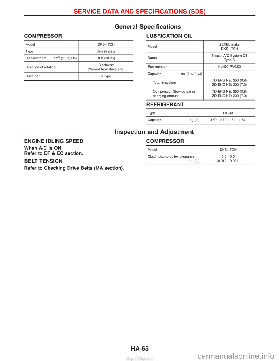
General Specifications
COMPRESSOR
ModelDKS-17CH
Type Swash plate
Displacement cm
3(cu in)/Rev 168 (10.25)
Direction of rotation Clockwise
(Viewed from drive end)
Drive belt A type
LUBRICATION OIL
ModelZEXEL make
DKS-17CH
Name Nissan A/C System Oil
Type S
Part number KLH00-PAGS0
Capacity m (Imp fl oz)
Total in system TD ENGINE: 250 (8.8)
ZD ENGINE: 200 (7.0)
Compressor (Service parts)
charging amount TD ENGINE: 250 (8.8)
ZD ENGINE: 200 (7.0)
REFRIGERANT
Type
R134a
Capacity kg (lb) 0.60 - 0.70 (1.32 - 1.54)
Inspection and Adjustment
ENGINE IDLING SPEED
When A/C is ON
Refer to EF & EC section.
BELT TENSION
Refer to Checking Drive Belts (MA section).
COMPRESSOR
Model DKS-17CH
Clutch disc-to-pulley clearance mm (in)0.3 - 0.6
(0.012 - 0.024)
SERVICE DATA AND SPECIFICATIONS (SDS)
HA-65
http://vnx.su/
Page 1463 of 1833

NOTES
http://vnx.su/
Page 1464 of 1833
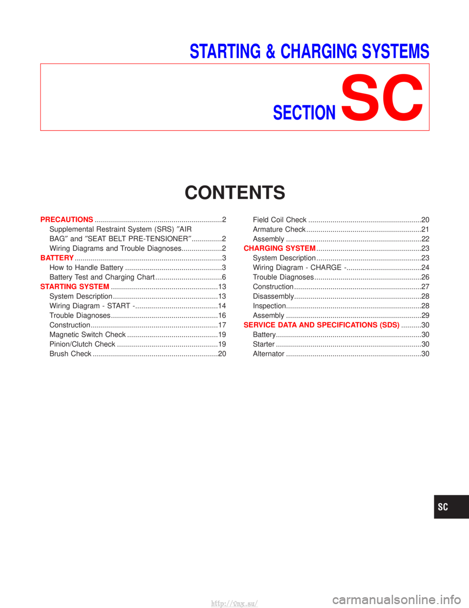
STARTING & CHARGING SYSTEMSSECTION
SC
CONTENTS
PRECAUTIONS ...............................................................2
Supplemental Restraint System (SRS) ²AIR
BAG² and²SEAT BELT PRE-TENSIONER² ...............2
Wiring Diagrams and Trouble Diagnoses....................2
BATTERY ........................................................................\
.3
How to Handle Battery ................................................3
Battery Test and Charging Chart .................................6
STARTING SYSTEM .....................................................13
System Description ....................................................13
Wiring Diagram - START -.........................................14
Trouble Diagnoses.....................................................16
Construction ...............................................................17
Magnetic Switch Check .............................................19
Pinion/Clutch Check ..................................................19
Brush Check ..............................................................20 Field Coil Check ........................................................20
Armature Check .........................................................21
Assembly ...................................................................22
CHARGING SYSTEM ....................................................23
System Description ....................................................23
Wiring Diagram - CHARGE -.....................................24
Trouble Diagnoses.....................................................26
Construction ...............................................................27
Disassembly...............................................................28
Inspection...................................................................28
Assembly ...................................................................29
SERVICE DATA AND SPECIFICATIONS (SDS) ..........30
Battery........................................................................\
30
Starter ........................................................................\
30
Alternator ...................................................................30
http://vnx.su/
Page 1465 of 1833
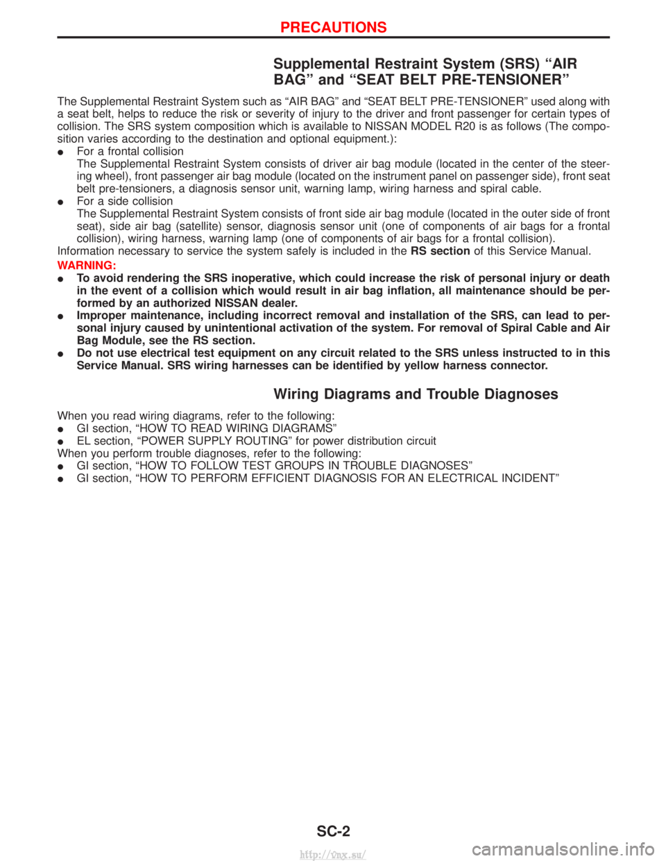
Supplemental Restraint System (SRS) ªAIR
BAGº and ªSEAT BELT PRE-TENSIONERº
The Supplemental Restraint System such as ªAIR BAGº and ªSEAT BELT PRE-TENSIONERº used along with
a seat belt, helps to reduce the risk or severity of injury to the driver and front passenger for certain types of
collision. The SRS system composition which is available to NISSAN MODEL R20 is as follows (The compo-
sition varies according to the destination and optional equipment.):
IFor a frontal collision
The Supplemental Restraint System consists of driver air bag module (located in the center of the steer-
ing wheel), front passenger air bag module (located on the instrument panel on passenger side), front seat
belt pre-tensioners, a diagnosis sensor unit, warning lamp, wiring harness and spiral cable.
I For a side collision
The Supplemental Restraint System consists of front side air bag module (located in the outer side of front
seat), side air bag (satellite) sensor, diagnosis sensor unit (one of components of air bags for a frontal
collision), wiring harness, warning lamp (one of components of air bags for a frontal collision).
Information necessary to service the system safely is included in the RS sectionof this Service Manual.
WARNING:
I To avoid rendering the SRS inoperative, which could increase the risk of personal injury or death
in the event of a collision which would result in air bag inflation, all maintenance should be per-
formed by an authorized NISSAN dealer.
I Improper maintenance, including incorrect removal and installation of the SRS, can lead to per-
sonal injury caused by unintentional activation of the system. For removal of Spiral Cable and Air
Bag Module, see the RS section.
I Do not use electrical test equipment on any circuit related to the SRS unless instructed to in this
Service Manual. SRS wiring harnesses can be identified by yellow harness connector.
Wiring Diagrams and Trouble Diagnoses
When you read wiring diagrams, refer to the following:
IGI section, ªHOW TO READ WIRING DIAGRAMSº
I EL section, ªPOWER SUPPLY ROUTINGº for power distribution circuit
When you perform trouble diagnoses, refer to the following:
I GI section, ªHOW TO FOLLOW TEST GROUPS IN TROUBLE DIAGNOSESº
I GI section, ªHOW TO PERFORM EFFICIENT DIAGNOSIS FOR AN ELECTRICAL INCIDENTº
PRECAUTIONS
SC-2
http://vnx.su/
Page 1466 of 1833
How to Handle Battery
CAUTION:
If it becomes necessary to start the engine with a booster bat-
tery and jumper cables,
1) Use a 12-volt booster battery.
2) After connecting battery cables, ensure that they aretightly clamped to battery terminals for good contact.
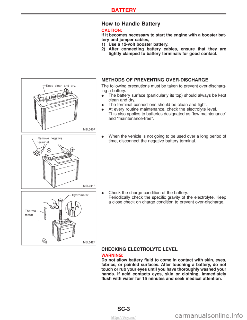
METHODS OF PREVENTING OVER-DISCHARGE
The following precautions must be taken to prevent over-discharg-
ing a battery.
IThe battery surface (particularly its top) should always be kept
clean and dry.
I The terminal connections should be clean and tight.
I At every routine maintenance, check the electrolyte level.
This also applies to batteries designated as ªlow maintenanceº
and ªmaintenance-freeº.
I When the vehicle is not going to be used over a long period of
time, disconnect the negative battery terminal.
I Check the charge condition of the battery.
Periodically check the specific gravity of the electrolyte. Keep
a close check on charge condition to prevent over-discharge.
CHECKING ELECTROLYTE LEVEL
WARNING:
Do not allow battery fluid to come in contact with skin, eyes,
fabrics, or painted surfaces. After touching a battery, do not
touch or rub your eyes until you have thoroughly washed your
hands. If acid contacts eyes, skin or clothing, immediately
flush with water for 15 minutes and seek medical attention.
MEL040F
MEL041F
MEL042F
BATTERY
SC-3
http://vnx.su/
Page 1467 of 1833
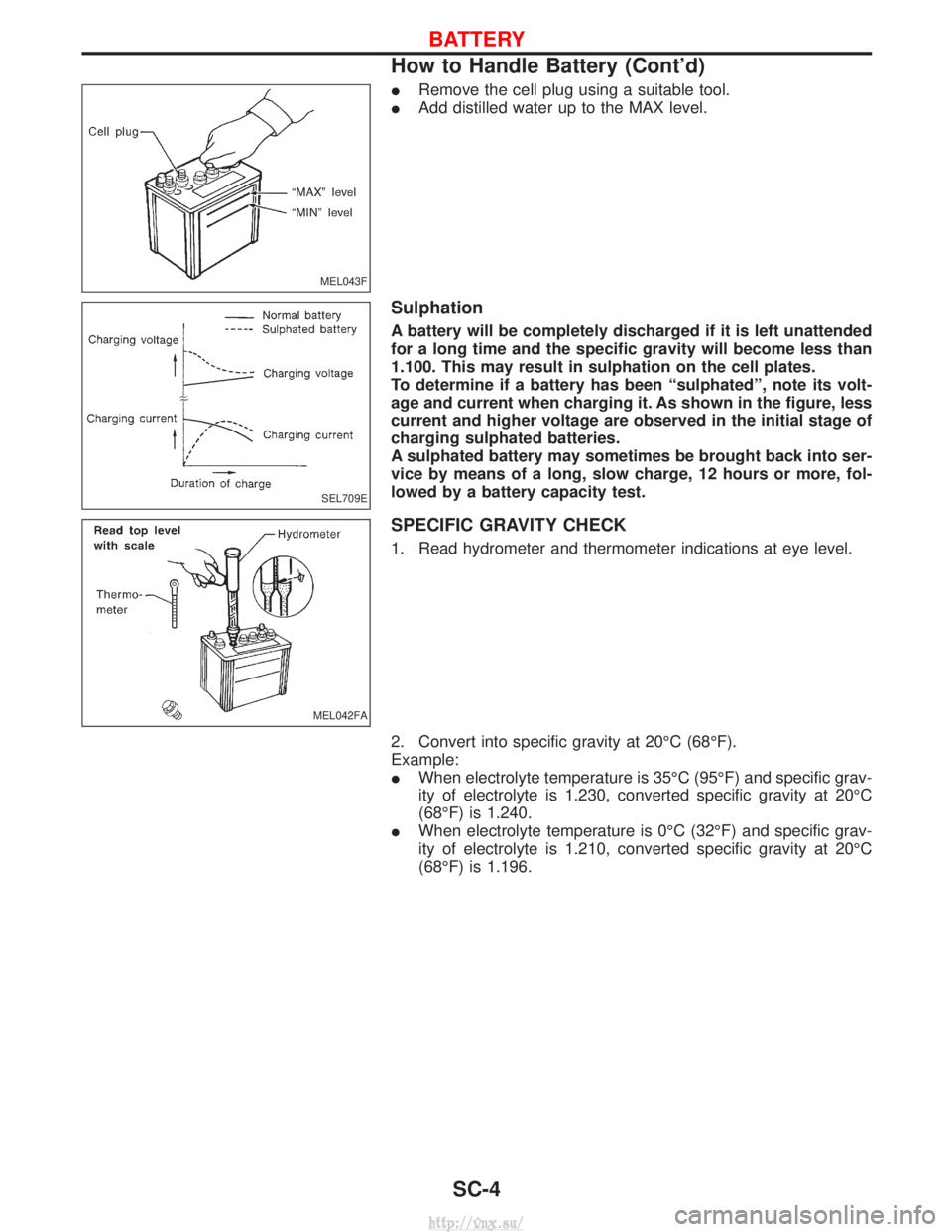
IRemove the cell plug using a suitable tool.
I Add distilled water up to the MAX level.
Sulphation
A battery will be completely discharged if it is left unattended
for a long time and the specific gravity will become less than
1.100. This may result in sulphation on the cell plates.
To determine if a battery has been ªsulphatedº, note its volt-
age and current when charging it. As shown in the figure, less
current and higher voltage are observed in the initial stage of
charging sulphated batteries.
A sulphated battery may sometimes be brought back into ser-
vice by means of a long, slow charge, 12 hours or more, fol-
lowed by a battery capacity test.
SPECIFIC GRAVITY CHECK
1. Read hydrometer and thermometer indications at eye level.
2. Convert into specific gravity at 20ÉC (68ÉF).
Example:
IWhen electrolyte temperature is 35ÉC (95ÉF) and specific grav-
ity of electrolyte is 1.230, converted specific gravity at 20ÉC
(68ÉF) is 1.240.
I When electrolyte temperature is 0ÉC (32ÉF) and specific grav-
ity of electrolyte is 1.210, converted specific gravity at 20ÉC
(68ÉF) is 1.196.
MEL043F
SEL709E
MEL042FA
BATTERY
How to Handle Battery (Cont'd)
SC-4
http://vnx.su/
Page 1468 of 1833

SEL007Z
BATTERY
How to Handle Battery (Cont'd)SC-5
http://vnx.su/
Page 1469 of 1833
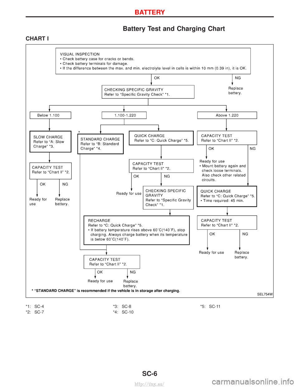
Battery Test and Charging Chart
CHART I
*1: SC-4
*2: SC-7*3: SC-8
*4: SC-10*5: SC-11
SEL754W
BATTERY
SC-6
http://vnx.su/
Page 1470 of 1833
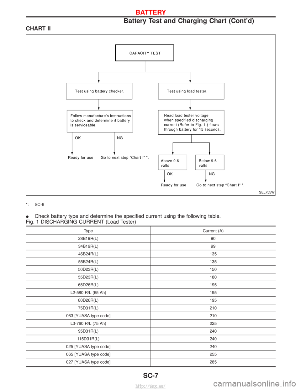
CHART II
*: SC-6
ICheck battery type and determine the specified current using the following table.
Fig. 1 DISCHARGING CURRENT (Load Tester)
Type Current (A)
28B19R(L) 90
34B19R(L) 99
46B24R(L) 135
55B24R(L) 135
50D23R(L) 150
55D23R(L) 180
65D26R(L) 195
L2-580 R/L (65 Ah) 195
80D26R(L) 195
75D31R(L) 210
063 [YUASA type code] 210
L3-760 R/L (75 Ah) 225
95D31R(L) 240
115D31R(L) 240
025 [YUASA type code] 240
065 [YUASA type code] 255
027 [YUASA type code] 285
SEL755W
BATTERY
Battery Test and Charging Chart (Cont'd)
SC-7
http://vnx.su/