NISSAN TIIDA 2007 Service Repair Manual
Manufacturer: NISSAN, Model Year: 2007, Model line: TIIDA, Model: NISSAN TIIDA 2007Pages: 5883, PDF Size: 78.95 MB
Page 3661 of 5883

INL-10
< FUNCTION DIAGNOSIS >
DIAGNOSIS SYSTEM (BCM)
DIAGNOSIS SYSTEM (BCM)
COMMON ITEM
COMMON ITEM : CONSULT-III Function (BCM - COMMON ITEM)INFOID:0000000001728866
APPLICATION ITEM
CONSULT-III performs the following functions via CAN communication with BCM.
INT LAMP
INT LAMP : CONSULT-III Function (BCM - INT LAMP)INFOID:0000000001728867
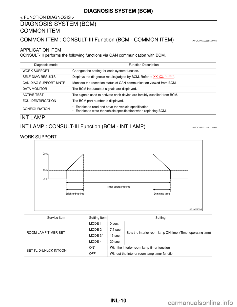
WORK SUPPORT
Diagnosis mode Function Description
WORK SUPPORT Changes the setting for each system function.
SELF-DIAG RESULTS Displays the diagnosis results judged by BCM. Refer to XX-XX, "*****"
.
CAN DIAG SUPPORT MNTR Monitors the reception status of CAN communication viewed from BCM.
DATA MONITOR The BCM input/output signals are displayed.
ACTIVE TEST The signals used to activate each device are forcibly supplied from BCM.
ECU IDENTIFICATION The BCM part number is displayed.
CONFIGURATION Enables to read and save the vehicle specification.
Enables to write the vehicle specification when replacing BCM.
JPLIA0093GB
Service item Setting item Setting
ROOM LAMP TIMER SETMODE 1 0 sec.
Sets the interior room lamp ON time. (Timer operating time) MODE 2 7.5 sec.
MODE 3* 15 sec.
MODE 4 30 sec.
SET I/L D-UNLCK INTCONON* With the interior room lamp timer function
OFF Without the interior room lamp timer function
Page 3662 of 5883

DIAGNOSIS SYSTEM (BCM)
INL-11
< FUNCTION DIAGNOSIS >
C
D
E
F
G
H
I
J
K
MA
B
INL
N
O
P
*: Initial setting
DATA MONITOR
ROOM LAMP ON TIME SETMODE 1 0.5 sec.
Sets the interior room lamp gradual brightening time. MODE 2* 1 sec.
MODE 3 2 sec.
MODE 4 3 sec.
MODE 5 4 sec.
MODE 6 5 sec.
MODE 7 0 sec.
ROOM LAMP OFF TIME SETMODE 1 0.5 sec.
Sets the interior room lamp gradual dimming time. MODE 2* 1 sec.
MODE 3 2 sec.
MODE 4 3 sec.
MODE 5 4 sec.
MODE 6 5 sec.
MODE 7 0 sec.
R LAMP TIMER LOGIC SETMODE 1* Interior room lamp timer activates with synchronizing all doors.
MODE 2Interior room lamp timer activates with synchronizing the driver door
only. Service item Setting item Setting
Monitor item
[Unit]Description
IGN ON SW
[ON/OFF]Ignition switch (ON) status judges from IGN signal (ignition power supply)
ACC SW
[ON/OFF]Ignition switch (ACC) status judges from ACC signal (ACC power supply)
KEY ON SW
[ON/OFF]The switch status input from key switch
PUSH SW
[ON/OFF]Push switch status received from Intelligent Key unit by CAN communication
DOOR SW-DR
[ON/OFF]The switch status input from front door switch (driver side)
DOOR SW-AS
[ON/OFF]The switch status input from front door switch (passenger side)
DOOR SW-RR
[ON/OFF]The switch status input from rear door switch RH
DOOR SW- RL
[ON/OFF]The switch status input from rear door switch LH
BACK DOOR SW
[ON/OFF]The switch status input from back door switch
CDL LOCK SW
[ON/OFF]Lock switch status input from door lock and unlock switch
CDL UNLOCK SW
[ON/OFF]Unlock switch status input from door lock and unlock switch
I-KEY LOCK
[ON/OFF]Lock signal status received from Intelligent Key unit by CAN communication
I-KEY UNLOCK
[ON/OFF]Unlock signal status received from Intelligent Key unit by CAN communication
Page 3663 of 5883

INL-12
< FUNCTION DIAGNOSIS >
DIAGNOSIS SYSTEM (BCM)
ACTIVE TEST
BATTERY SAVER
BATTERY SAVER : CONSULT-III Function (BCM - BATTERY SAVER)INFOID:0000000001728868
WORK SUPPORT
*: Initial setting
DATA MONITOR
KEYLESS LOCK
[ON/OFF]Lock signal status received from remote keyless entry receiver (integrated in the
BCM)
KEYLESS UNLOCK
[ON/OFF]Unlock signal status received from remote keyless entry receiver (integrated in the
BCM) Monitor item
[Unit]Description
Test item Operation Description
INT LAMPONOutputs the interior room lamp control signal to turn the interior room lamps ON.
[Map lamp, personal lamp, room lamp, luggage room lamp (when applicable lamps
switch is in DOOR position.)]
OFF Stops the interior room lamp control signal to turn the interior room lamps.
Service item Setting item Setting
ROOM LAMP TIMER SETMODE 1* 30 min.
Sets the interior room lamp battery saver timer operating
time.
MODE 2 60 min.
Monitor item
[Unit]Description
IGN ON SW
[ON/OFF]Ignition switch (ON) status judges from IGN signal (ignition power supply)
ACC SW
[ON/OFF]Ignition switch (ACC) status judges from ACC signal (ACC power supply)
KEY ON SW
[ON/OFF]The switch status input from key switch
PUSH SW
[ON/OFF]Push switch status received from Intelligent Key unit by CAN communication
DOOR SW-DR
[ON/OFF]The switch status input from front door switch (driver side)
DOOR SW-AS
[ON/OFF]The switch status input from front door switch (passenger side)
DOOR SW-RR
[ON/OFF]The switch status input from rear door switch RH
DOOR SW- RL
[ON/OFF]The switch status input from rear door switch LH
BACK DOOR SW
[ON/OFF]The switch status input from back door switch
CDL LOCK SW
[ON/OFF]Lock switch status input from door lock and unlock switch
CDL UNLOCK SW
[ON/OFF]Unlock switch status input from door lock and unlock switch
I-KEY LOCK
[ON/OFF]Lock signal status received from Intelligent Key unit by CAN communication
Page 3664 of 5883
![NISSAN TIIDA 2007 Service Repair Manual DIAGNOSIS SYSTEM (BCM)
INL-13
< FUNCTION DIAGNOSIS >
C
D
E
F
G
H
I
J
K
MA
B
INL
N
O
P
ACTIVE TEST
*: Each lamp switch is in ON position.I-KEY UNLOCK
[ON/OFF]Unlock signal status received from Intellig NISSAN TIIDA 2007 Service Repair Manual DIAGNOSIS SYSTEM (BCM)
INL-13
< FUNCTION DIAGNOSIS >
C
D
E
F
G
H
I
J
K
MA
B
INL
N
O
P
ACTIVE TEST
*: Each lamp switch is in ON position.I-KEY UNLOCK
[ON/OFF]Unlock signal status received from Intellig](/img/5/57395/w960_57395-3663.png)
DIAGNOSIS SYSTEM (BCM)
INL-13
< FUNCTION DIAGNOSIS >
C
D
E
F
G
H
I
J
K
MA
B
INL
N
O
P
ACTIVE TEST
*: Each lamp switch is in ON position.I-KEY UNLOCK
[ON/OFF]Unlock signal status received from Intelligent Key unit by CAN communication
KEYLESS LOCK
[ON/OFF]Lock signal status received from remote keyless entry receiver (integrated in the
BCM)
KEYLESS UNLOCK
[ON/OFF]Unlock signal status received from remote keyless entry receiver (integrated in the
BCM) Monitor item
[Unit]Description
Test item Operation Description
BATTERY SAVEROFF Cuts the interior room lamp power supply to turn interior room lamps OFF.
ON Outputs the interior room lamp power supply to turn interior room lamps ON.*
Page 3665 of 5883

INL-14
< COMPONENT DIAGNOSIS >
POWER SUPPLY AND GROUND CIRCUIT
COMPONENT DIAGNOSIS
POWER SUPPLY AND GROUND CIRCUIT
BCM
BCM : Diagnosis ProcedureINFOID:0000000001728869
For information about power and ground inspection for the BCM, refer to BCS-30, "Diagnosis Procedure".
Page 3666 of 5883

INTERIOR ROOM LAMP POWER SUPPLY CIRCUIT
INL-15
< COMPONENT DIAGNOSIS >
C
D
E
F
G
H
I
J
K
MA
B
INL
N
O
P
INTERIOR ROOM LAMP POWER SUPPLY CIRCUIT
DescriptionINFOID:0000000001728870
Provides the interior room lamp power supply. Also cuts the power supply when the interior room lamp battery
saver activating.
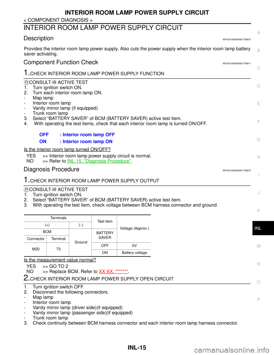
Component Function CheckINFOID:0000000001728871
1.CHECK INTERIOR ROOM LAMP POWER SUPPLY FUNCTION
CONSULT-III ACTIVE TEST
1. Turn ignition switch ON.
2. Turn each interior room lamp ON.
- Map lamp
- Interior room lamp
- Vanity mirror lamp (if equipped)
- Trunk room lamp
3. Select “BATTERY SAVER” of BCM (BATTERY SAVER) active test item.
4. With operating the test items, check that each interior room lamp is turned ON/OFF.
Is the interior room lamp turned ON/OFF?
YES >> Interior room lamp power supply circuit is normal.
NO >> Refer to INL-15, "
Diagnosis Procedure".
Diagnosis ProcedureINFOID:0000000001728872
1.CHECK INTERIOR ROOM LAMP POWER SUPPLY OUTPUT
CONSULT-III ACTIVE TEST
1. Turn ignition switch ON.
2. Select “BATTERY SAVER” of BCM (BATTERY SAVER) active test item.
3. With operating the test item, check voltage between BCM harness connector and ground.
Is the measurement value normal?
YES >> GO TO 2
NO >> Replace BCM. Refer to XX-XX, "*****"
.
2.CHECK INTERIOR ROOM LAMP POWER SUPPLY OPEN CIRCUIT
1. Turn ignition switch OFF.
2. Disconnect the following connectors.
- Map lamp
- Interior room lamp
- Vanity mirror lamp (driver side)(if equipped)
- Vanity mirror lamp (passenger side)(if equipped)
- Trunk room lamp
3. Check continuity between BCM harness connector and each interior room lamp harness connector.OFF : Interior room lamp OFF
ON : Interior room lamp ON
Te r m i n a l s
Te s t i t e m
Voltage (Approx.) (+) (−)
BCM
GroundBATTERY
SAVER
Connector Terminal
M20 73OFF 0V
ON Battery voltage
Page 3667 of 5883

INL-16
< COMPONENT DIAGNOSIS >
INTERIOR ROOM LAMP POWER SUPPLY CIRCUIT
Does continuity exist?
YES >> GO TO 3
NO >> Repair the harnesses or connectors.
3.CHECK INTERIOR ROOM LAMP POWER SUPPLY SHORT CIRCUIT
Check continuity between BCM harness connector and ground.
Does continuity exist?
YES >> Repair the harnesses or connectors.
NO >> Check that each interior room lamp has no internal short circuit.
BCM Each interior room lamp
Continu-
ity Connec-
torTerminal Connector Terminal
M20 73Map lamp R2 4
Existed Interior room lamp R7 3
Vanity mirror lamp
RHR10 1
Vanity mirror lamp
LHR9 1
Trunk room lamp B36 1
BCM
GroundContinuity
Connector Terminal
M20 73 Not existed
Page 3668 of 5883

INTERIOR ROOM LAMP CONTROL SYSTEM
INL-17
< COMPONENT DIAGNOSIS >
C
D
E
F
G
H
I
J
K
MA
B
INL
N
O
P
INTERIOR ROOM LAMP CONTROL SYSTEM
Wiring Diagram - INTERIOR ROOM LAMP -INFOID:0000000001728876
ALLWA0124GB
Page 3669 of 5883

INL-18
< COMPONENT DIAGNOSIS >
INTERIOR ROOM LAMP CONTROL SYSTEM
ALLWA0125GB
Page 3670 of 5883

INTERIOR ROOM LAMP CONTROL SYSTEM
INL-19
< COMPONENT DIAGNOSIS >
C
D
E
F
G
H
I
J
K
MA
B
INL
N
O
P
ALLWA0126GB