NISSAN TIIDA 2007 Service Repair Manual
Manufacturer: NISSAN, Model Year: 2007, Model line: TIIDA, Model: NISSAN TIIDA 2007Pages: 5883, PDF Size: 78.95 MB
Page 5821 of 5883
FRONT WIPER MOTOR LO CIRCUIT
WW-19
< COMPONENT DIAGNOSIS >
C
D
E
F
G
H
I
J
K
MA
B
WW
N
O
P
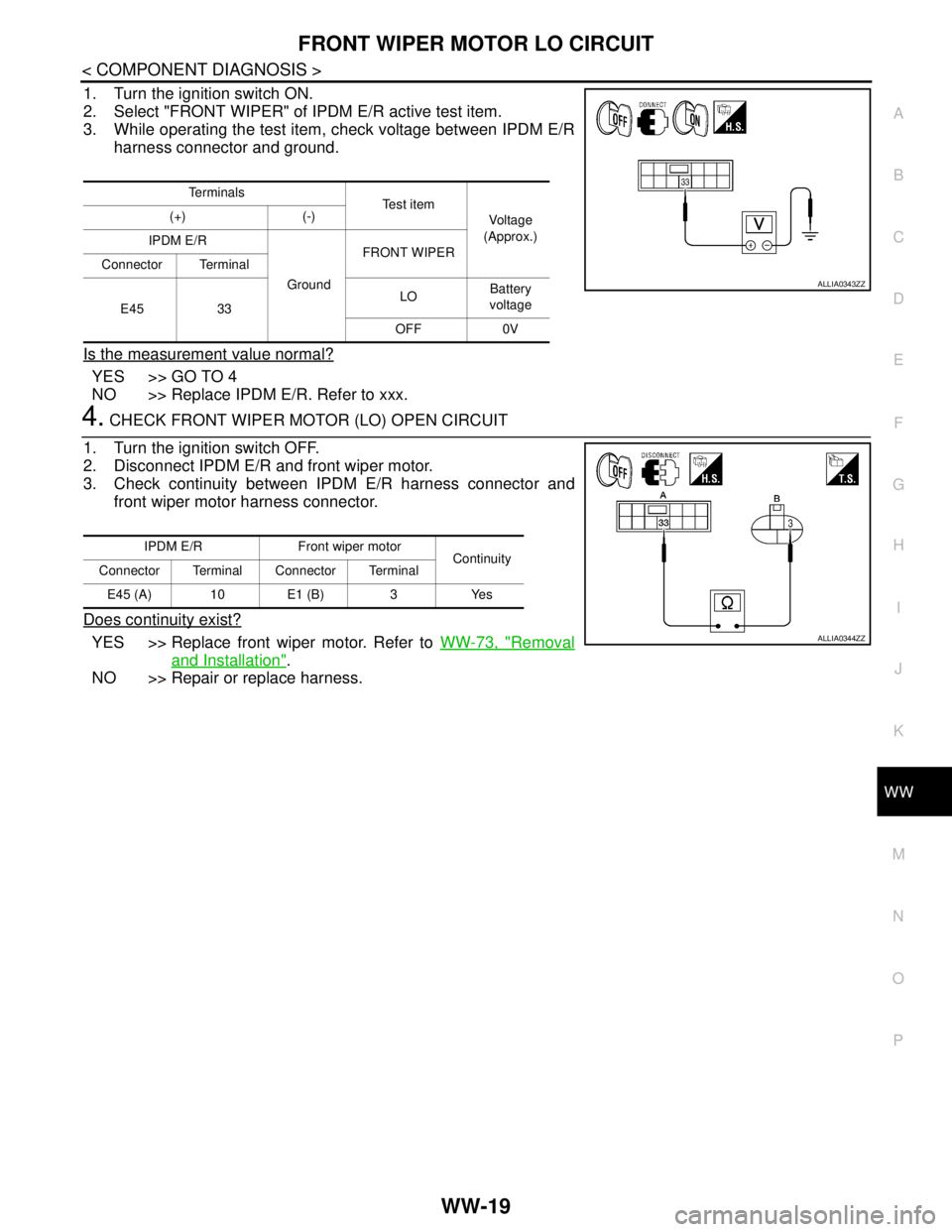
1. Turn the ignition switch ON.
2. Select "FRONT WIPER" of IPDM E/R active test item.
3. While operating the test item, check voltage between IPDM E/R
harness connector and ground.
Is the measurement value normal?
YES >> GO TO 4
NO >> Replace IPDM E/R. Refer to xxx.
4. CHECK FRONT WIPER MOTOR (LO) OPEN CIRCUIT
1. Turn the ignition switch OFF.
2. Disconnect IPDM E/R and front wiper motor.
3. Check continuity between IPDM E/R harness connector and
front wiper motor harness connector.
Does continuity exist?
YES >> Replace front wiper motor. Refer to WW-73, "Removal
and Installation".
NO >> Repair or replace harness.
Te r m i n a l s
Te s t i t e m
Voltage
(Approx.) (+) (-)
IPDM E/R
GroundFRONT WIPER
Connector Terminal
E45 33LOBattery
voltage
OFF 0V
ALLIA0343ZZ
IPDM E/R Front wiper motor
Continuity
Connector Terminal Connector Terminal
E45 (A) 10 E1 (B) 3 Yes
ALLIA0344ZZ
Page 5822 of 5883
WW-20
< COMPONENT DIAGNOSIS >
FRONT WIPER MOTOR HI CIRCUIT
FRONT WIPER MOTOR HI CIRCUIT
Component Function CheckINFOID:0000000001366612
1. CHECK FRONT WIPER HI OPERATION
IPDM E/R AUTO ACTIVE TEST
1. Start IPDM E/R auto active test. Refer to PCS-10, "
Diagnosis Description".
2. Check that the front wiper operates at the HI operation.
CONSULT-III ACTIVE TEST
1. Select "FRONT WIPER" of IPDM E/R active test item.
2. While operating the test item, check front wiper operation.
Is front wiper (HI) operation normal?
YES >> Front wiper motor HI circuit is normal.
NO >> Refer to WW-20, "
Diagnosis Procedure".
Diagnosis ProcedureINFOID:0000000001366613
1. CHECK FRONT WIPER MOTOR FUSE
1. Turn the ignition switch OFF.
2. Check that the following fuse is not blown.
Is the fuse blown?
YES >> GO TO 2
NO >> GO TO 3
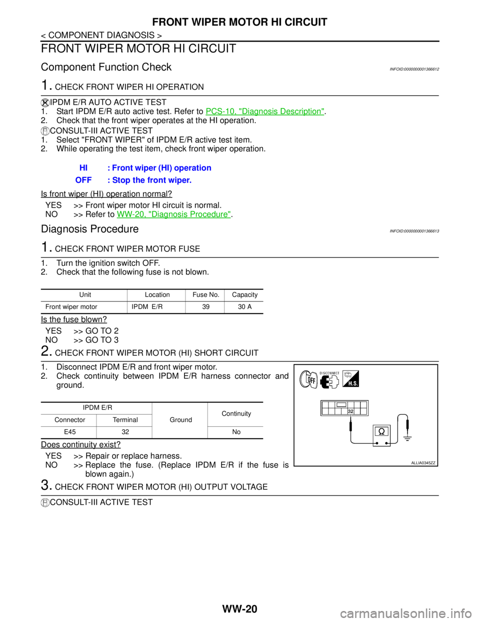
2. CHECK FRONT WIPER MOTOR (HI) SHORT CIRCUIT
1. Disconnect IPDM E/R and front wiper motor.
2. Check continuity between IPDM E/R harness connector and
ground.
Does continuity exist?
YES >> Repair or replace harness.
NO >> Replace the fuse. (Replace IPDM E/R if the fuse is
blown again.)
3. CHECK FRONT WIPER MOTOR (HI) OUTPUT VOLTAGE
CONSULT-III ACTIVE TESTHI : Front wiper (HI) operation
OFF : Stop the front wiper.
Unit Location Fuse No. Capacity
Front wiper motor IPDM E/R 39 30 A
IPDM E/R
GroundContinuity
Connector Terminal
E45 32 No
ALLIA0345ZZ
Page 5823 of 5883
FRONT WIPER MOTOR HI CIRCUIT
WW-21
< COMPONENT DIAGNOSIS >
C
D
E
F
G
H
I
J
K
MA
B
WW
N
O
P
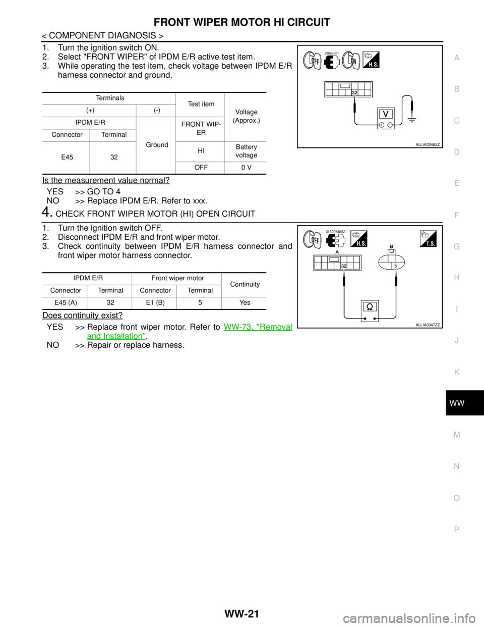
1. Turn the ignition switch ON.
2. Select "FRONT WIPER" of IPDM E/R active test item.
3. While operating the test item, check voltage between IPDM E/R
harness connector and ground.
Is the measurement value normal?
YES >> GO TO 4
NO >> Replace IPDM E/R. Refer to xxx.
4. CHECK FRONT WIPER MOTOR (HI) OPEN CIRCUIT
1. Turn the ignition switch OFF.
2. Disconnect IPDM E/R and front wiper motor.
3. Check continuity between IPDM E/R harness connector and
front wiper motor harness connector.
Does continuity exist?
YES >> Replace front wiper motor. Refer to WW-73, "Removal
and Installation".
NO >> Repair or replace harness.
Te r m i n a l s
Te s t i t e m
Voltage
(Approx.) (+) (-)
IPDM E/R
GroundFRONT WIP-
ER
Connector Terminal
E45 32HIBattery
voltage
OFF 0 V
ALLIA0346ZZ
IPDM E/R Front wiper motor
Continuity
Connector Terminal Connector Terminal
E45 (A) 32 E1 (B) 5 Yes
ALLIA0347ZZ
Page 5824 of 5883
WW-22
< COMPONENT DIAGNOSIS >
FRONT WIPER AUTO STOP SIGNAL CIRCUIT
FRONT WIPER AUTO STOP SIGNAL CIRCUIT
Component Function CheckINFOID:0000000001366614
1. CHECK FRONT WIPER (AUTO STOP) SIGNAL CHECK
CONSULT-III DATA MONITOR
1. Select "FRONT WIPER STOP" of IPDM E/R data monitor item.
2. Operate the front wiper.
3. Check that "FR WIPER STOP" changes to "STOP P" and "ACT P" linked with the wiper operation.
Is the status of item normal?
YES >> Front wiper auto stop signal circuit is normal.
NO >> Refer to WW-22, "
Diagnosis Procedure".
Diagnosis ProcedureINFOID:0000000001366615
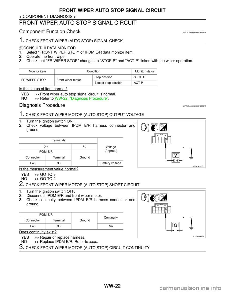
1. CHECK FRONT WIPER MOTOR (AUTO STOP) OUTPUT VOLTAGE
1. Turn the ignition switch ON.
2. Check voltage between IPDM E/R harness connector and
ground.
Is the measurement value normal?
YES >> GO TO 3
NO >> GO TO 2
2. CHECK FRONT WIPER MOTOR (AUTO STOP) SHORT CIRCUIT
1. Turn the ignition switch OFF.
2. Disconnect IPDM E/R and front wiper motor.
3. Check continuity between IPDM E/R harness connector and
ground.
Does continuity exist?
YES >> Repair or replace harness.
NO >> Replace IPDM E/R. Refer to xxxx.
3. CHECK FRONT WIPER MOTOR (AUTO STOP) CIRCUIT CONTINUITY
Monitor item Condition Monitor status
FR WIPER STOP Front wiper motorStop position STOP P
Except stop position ACT P
Te r m i n a l s
Voltage
(Approx.) (+) (-)
IPDM E/R
Ground Connector Terminal
E46 38 Battery voltage
WKIA5491E
IPDM E/R
GroundContinuity
Connector Terminal
E46 38 No
ALLIA0348ZZ
Page 5825 of 5883
FRONT WIPER AUTO STOP SIGNAL CIRCUIT
WW-23
< COMPONENT DIAGNOSIS >
C
D
E
F
G
H
I
J
K
MA
B
WW
N
O
P
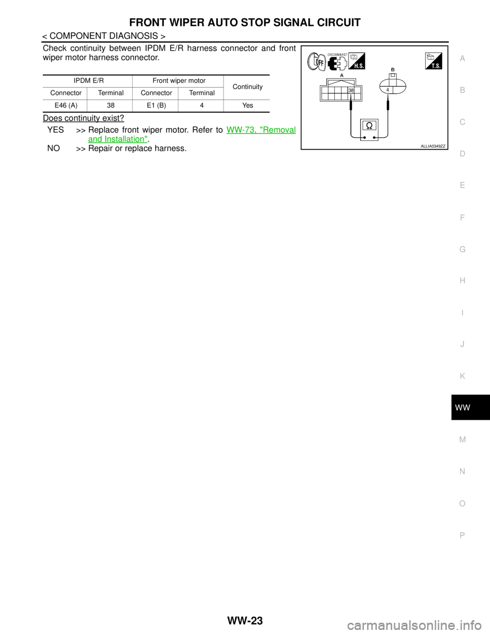
Check continuity between IPDM E/R harness connector and front
wiper motor harness connector.
Does continuity exist?
YES >> Replace front wiper motor. Refer to WW-73, "Removal
and Installation".
NO >> Repair or replace harness.
IPDM E/R Front wiper motor
Continuity
Connector Terminal Connector Terminal
E46 (A) 38 E1 (B) 4 Yes
ALLIA0349ZZ
Page 5826 of 5883
WW-24
< COMPONENT DIAGNOSIS >
FRONT WIPER MOTOR GROUND CIRCUIT
FRONT WIPER MOTOR GROUND CIRCUIT
Diagnosis ProcedureINFOID:0000000001366616
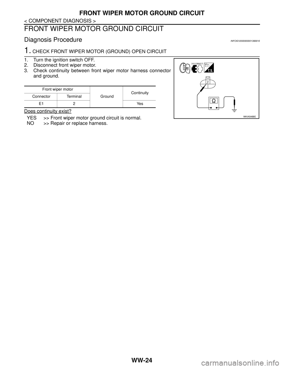
1. CHECK FRONT WIPER MOTOR (GROUND) OPEN CIRCUIT
1. Turn the ignition switch OFF.
2. Disconnect front wiper motor.
3. Check continuity between front wiper motor harness connector
and ground.
Does continuity exist?
YES >> Front wiper motor ground circuit is normal.
NO >> Repair or replace harness.
Front wiper motor
GroundContinuity
Connector Terminal
E1 2 Yes
WKIA5488E
Page 5827 of 5883
WASHER SWITCH
WW-25
< COMPONENT DIAGNOSIS >
C
D
E
F
G
H
I
J
K
MA
B
WW
N
O
P
WASHER SWITCH
DescriptionINFOID:0000000001366617
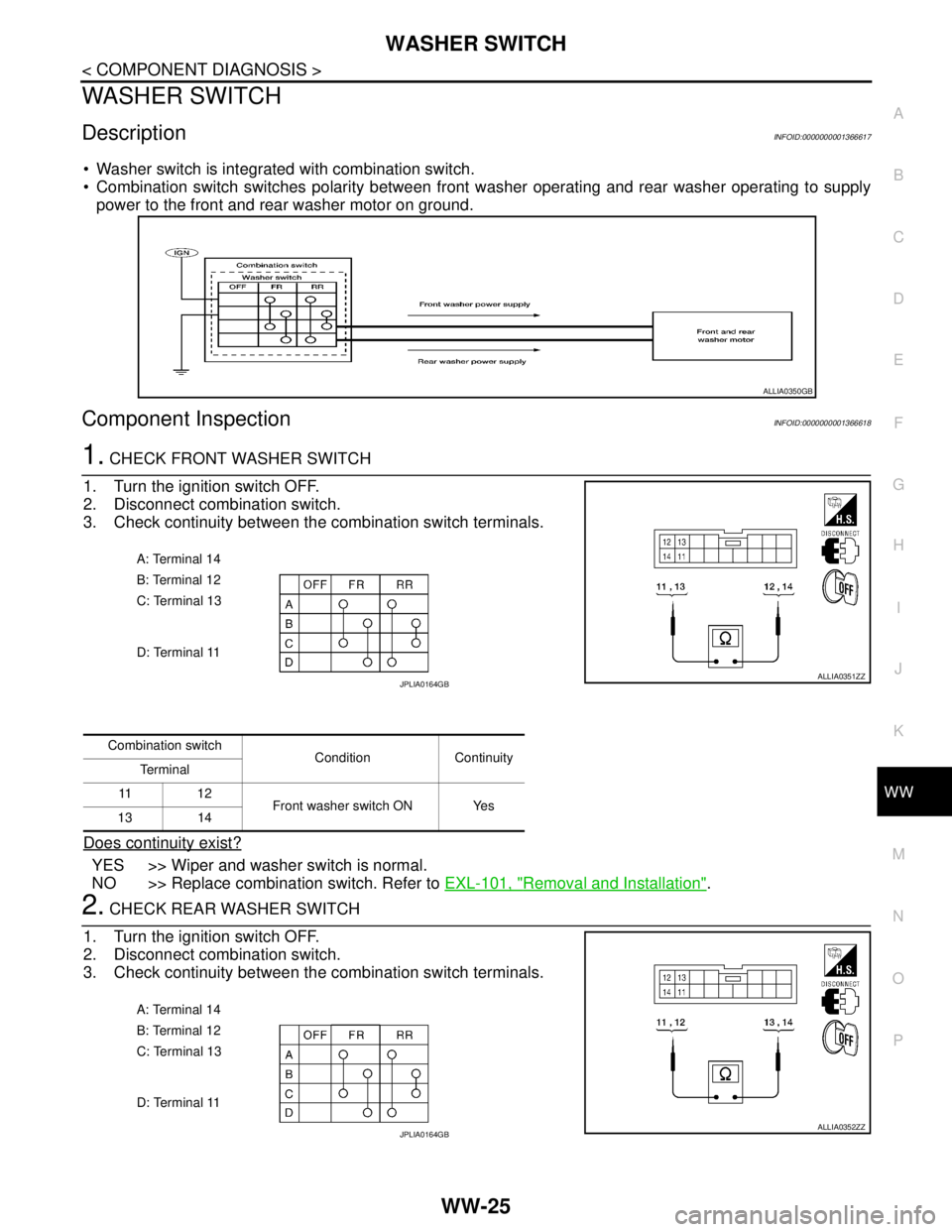
Washer switch is integrated with combination switch.
Combination switch switches polarity between front washer operating and rear washer operating to supply
power to the front and rear washer motor on ground.
Component InspectionINFOID:0000000001366618
1. CHECK FRONT WASHER SWITCH
1. Turn the ignition switch OFF.
2. Disconnect combination switch.
3. Check continuity between the combination switch terminals.
Does continuity exist?
YES >> Wiper and washer switch is normal.
NO >> Replace combination switch. Refer to EXL-101, "
Removal and Installation".
2. CHECK REAR WASHER SWITCH
1. Turn the ignition switch OFF.
2. Disconnect combination switch.
3. Check continuity between the combination switch terminals.
ALLIA0350GB
A: Terminal 14
B: Terminal 12
C: Terminal 13
D: Terminal 11
ALLIA0351ZZJPLIA0164GB
Combination switch
Condition Continuity
Te r m i n a l
11 1 2
Front washer switch ON Yes
13 14
A: Terminal 14
B: Terminal 12
C: Terminal 13
D: Terminal 11
ALLIA0352ZZJPLIA0164GB
Page 5828 of 5883

WW-26
< COMPONENT DIAGNOSIS >
WASHER SWITCH
Does continuity exist?
YES >> Wiper and washer switch is normal.
NO >> Replace combination switch. Refer to EXL-101, "
Removal and Installation".
Combination switch
Condition Continuity
Te r m i n a l
11 1 4
Rear washer switch ON Yes
12 13
Page 5829 of 5883

LIGHT & RAIN SENSOR
WW-27
< COMPONENT DIAGNOSIS >
C
D
E
F
G
H
I
J
K
MA
B
WW
N
O
P
LIGHT & RAIN SENSOR
DescriptionINFOID:0000000001366619
Detects water droplets on the windshield with infrared rays, and transmits the rain sensor signal to BCM
through the light and rain sensor serial link.
Diagnosis ProcedureINFOID:0000000001366620
Refer to EXL-55, "Component Function Check".
Page 5830 of 5883
WW-28
< COMPONENT DIAGNOSIS >
REAR WIPER MOTOR CIRCUIT
REAR WIPER MOTOR CIRCUIT
Component Function CheckINFOID:0000000001366621
1. CHECK REAR WIPER ON OPERATION
CONSULT-III ACTIVE TEST
1. Select "RR WIPER" of BCM active test item.
2. While operating the test item, check rear wiper operation.
Is rear wiper operation normal?
YES >> Rear wiper motor circuit is normal.
NO >> Refer to WW-28, "
Diagnosis Procedure".
Diagnosis ProcedureINFOID:0000000001366622
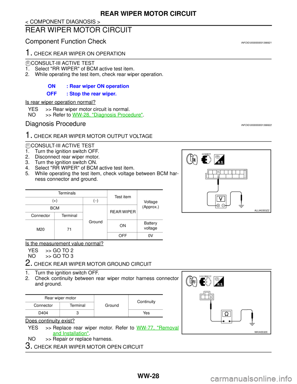
1. CHECK REAR WIPER MOTOR OUTPUT VOLTAGE
CONSULT-III ACTIVE TEST
1. Turn the ignition switch OFF.
2. Disconnect rear wiper motor.
3. Turn the ignition switch ON.
4. Select "RR WIPER" of BCM active test item.
5. While operating the test item, check voltage between BCM har-
ness connector and ground.
Is the measurement value normal?
YES >> GO TO 2
NO >> GO TO 3
2. CHECK REAR WIPER MOTOR GROUND CIRCUIT
1. Turn the ignition switch OFF.
2. Check continuity between rear wiper motor harness connector
and ground.
Does continuity exist?
YES >> Replace rear wiper motor. Refer to WW-77, "Removal
and Installation".
NO >> Repair or replace harness.
3. CHECK REAR WIPER MOTOR OPEN CIRCUIT ON : Rear wiper ON operation
OFF : Stop the rear wiper.
Te r m i n a l s
Te s t i t e m
Voltage
(Approx.) (+) (−)
BCM
GroundREAR WIPER
Connector Terminal
M20 71ONBattery
voltage
OFF 0V
ALLIA0353ZZ
Rear wiper motor
GroundContinuity
Connector Terminal
D404 3 Yes
WKIA5532E