NISSAN X-TRAIL 2003 Electronic Repair Manual
Manufacturer: NISSAN, Model Year: 2003, Model line: X-TRAIL, Model: NISSAN X-TRAIL 2003Pages: 3066, PDF Size: 51.47 MB
Page 2211 of 3066
FRONT DRIVE SHAFT
FAX-15
C
E
F
G
H
I
J
K
L
MA
B
FA X
Joint Assembly (Wheel Side)
CAUTION:
Joint assembly cannot be disassembled. Do not attempt to disassemble it.
ASSEMBLY
Transaxle Side
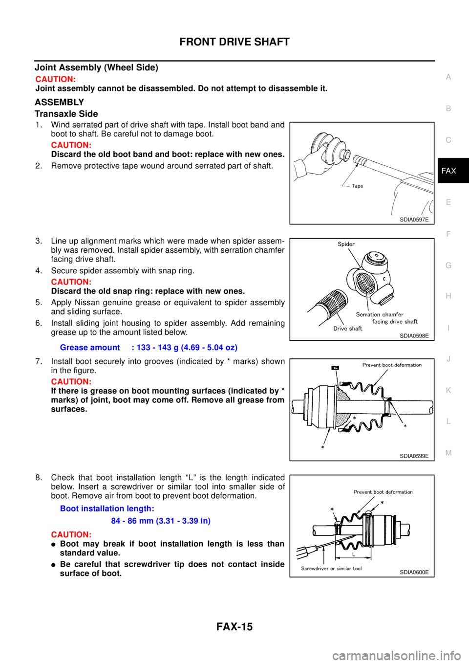
1. Wind serrated part of drive shaft with tape. Install boot band and
boot to shaft. Be careful not to damage boot.
CAUTION:
Discard the old boot band and boot: replace with new ones.
2. Remove protective tape wound around serrated part of shaft.
3. Line up alignment marks which were made when spider assem-
bly was removed. Install spider assembly, with serration chamfer
facing drive shaft.
4. Secure spider assembly with snap ring.
CAUTION:
Discard the old snap ring: replace with new ones.
5. Apply Nissan genuine grease or equivalent to spider assembly
and sliding surface.
6. Install sliding joint housing to spider assembly. Add remaining
grease up to the amount listed below.
7. Install boot securely into grooves (indicated by * marks) shown
in the figure.
CAUTION:
If there is grease on boot mounting surfaces (indicated by *
marks) of joint, boot may come off. Remove all grease from
surfaces.
8. Check that boot installation length “L” is the length indicated
below. Insert a screwdriver or similar tool into smaller side of
boot. Remove air from boot to prevent boot deformation.
CAUTION:
lBoot may break if boot installation length is less than
standard value.
lBe careful that screwdriver tip does not contact inside
surface of boot.
SDIA0597E
Grease amount : 133 - 143 g (4.69 - 5.04 oz)
SDIA0598E
SDIA0599E
Boot installation length:
84 - 86 mm (3.31 - 3.39 in)
SDIA0600E
Page 2212 of 3066
FAX-16
FRONT DRIVE SHAFT
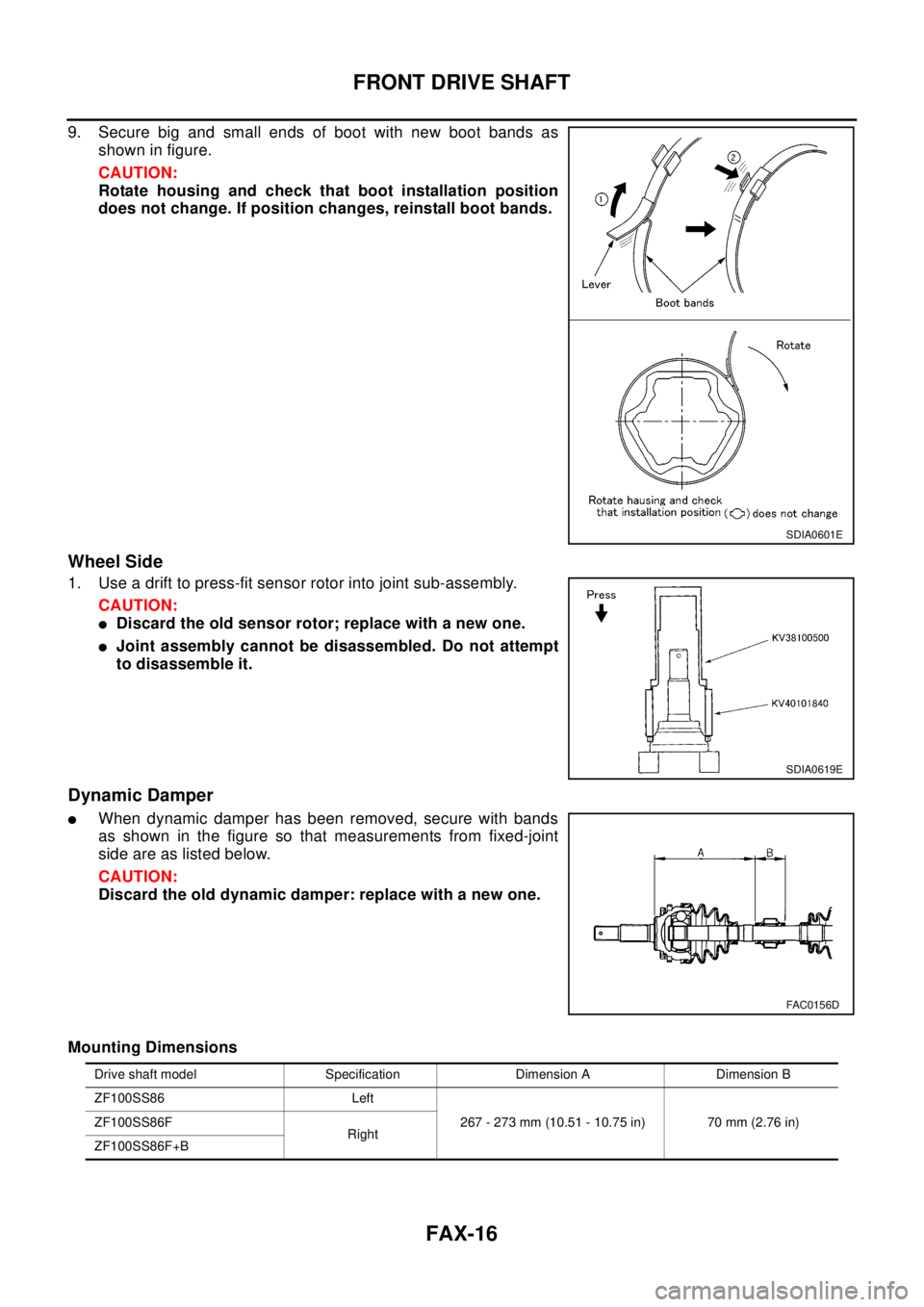
9. Secure big and small ends of boot with new boot bands as
shown in figure.
CAUTION:
Rotate housing and check that boot installation position
does not change. If position changes, reinstall boot bands.
Wheel Side
1. Use a drift to press-fit sensor rotor into joint sub-assembly.
CAUTION:
lDiscard the old sensor rotor; replace with a new one.
lJoint assembly cannot be disassembled. Do not attempt
to disassemble it.
Dynamic Damper
lWhen dynamic damper has been removed, secure with bands
as shown in the figure so that measurements from fixed-joint
side are as listed below.
CAUTION:
Discard the old dynamic damper: replace with a new one.
Mounting Dimensions
SDIA0601E
SDIA0619E
FAC0156D
Drive shaft model Specification Dimension A Dimension B
ZF100SS86 Left
267 - 273 mm (10.51 - 10.75 in) 70 mm (2.76 in) ZF100SS86F
Right
ZF100SS86F+B
Page 2213 of 3066
SERVICE DATA AND SPECIFICATIONS (SDS)
FAX-17
C
E
F
G
H
I
J
K
L
MA
B
FA X
SERVICE DATA AND SPECIFICATIONS (SDS)PFP:00030
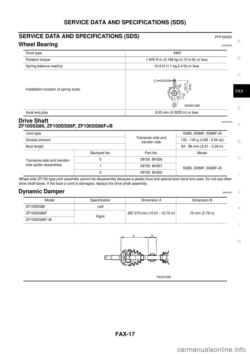
Wheel BearingEDS000IG
Drive ShaftEDS000IH
ZF100SS86, ZF100SS86F, ZF100SS86F+B
Wheel side ZF100 type joint assembly cannot be disassembly because a plastic boot and special boot band are used. Do not use other
drive shaft boots. If the boot or joint is damaged, replace the drive shaft assembly.
Dynamic DamperEDS0 00 II
Drive type4WD
Rotation torque 1.645 N·m (0.168 kg-m,15 in-lb) or less
Spring balance reading 10.6 N (1.1 kg,2.4 lb) or less
Installation location of spring scale
Axial end play 0.05 mm (0.0020 in) or less
SDIA0148E
Joint type
Transaxle side and
transfer sideSS86, SS86F, SS86F+B
Grease amount133-143g(4.69-5.04oz)
Boot length84 - 86 mm (3.31 - 3.39 in)
Transaxle-side and transfer-
side spider assembliesStamped No. Part No. Model
0 39720 8H300
SS86, SS86F, SS86F+B 1 39720 8H301
2 39720 8H302
Model Specification Dimension A Dimension B
ZF100SS86 Left
267 273 mm (10.51 - 10.75 in) 70 mm (2.76 in) ZF100SS86F
Right
ZF100SS86F+B
FAC0156D
Page 2214 of 3066

FAX-18
SERVICE DATA AND SPECIFICATIONS (SDS)
Page 2215 of 3066
PLEASE HELP US TO IMPROVE THIS
SERVICE MANUAL ON CD!
Your comments are important to NISSAN and will help us to improve our
Service Manuals on CD. Use this form to report any issues or comments you
may have regarding this Service Manual publication.
Please print this form and type or print your comments below. Mail or fax to:
NISSANEUROP EN.V.
S320 Service Engineering
2, Avenue de Denis Papin
ZIPEC - F92350 Le Plessis Robinson
France
Fax :+ 33 (0) 1 41 07 16 81
SERVICE MANUAL: Model:Language:
Publication Number:
Please describe any issues or problems in detail:
Page number(s):
Note: Please include acopy ofeach page, marked withyour comments.
Is the organization of the manual clear and easy to follow? (circle your answer) YES NO
Please comment:
What information should be included in NISSAN Service Manuals to better support you in
servicing or repairing customer vehicles?
Date :
Your Name :Position :
Dealer :Dealer No. :
Address :
City :Country :
Telephone :
Fax :
E-mail :
Page 2216 of 3066
FL-1
FUEL SYSTEM
B ENGINE
CONTENTS
C
D
E
F
G
H
I
J
K
L
M
SECTION
A
FL
FUEL SYSTEM
QR20DE
PREPARATION ........................................................... 2
Commercial Service Tool ......................................... 2
FUEL SYSTEM ........................................................... 3
Checking Fuel Lines ................................................. 3
General Precautions ................................................ 3
FUEL LEVEL SENSOR UNIT, FUEL FILTER AND
FUEL PUMP ASSEMBLY ........................................... 4
Removal and Installation .......................................... 4
REMOVAL ............................................................. 4
INSPECTION AFTER REMOVAL ......................... 6
INSTALLATION ..................................................... 6
INSPECTION AFTER INSTALLATION ................. 7
Disassembly and Assembly ..................................... 7
DISASSEMBLY ..................................................... 7
ASSEMBLY ........................................................... 8
FUEL TANK ................................................................ 9
Removal and Installation .......................................... 9
REMOVAL ............................................................. 9
INSTALLATION ................................................... 10
Inspection After Installation .....................................11
SERVICE DATA AND SPECIFICATIONS (SDS) ...... 12
Standard and Limit ................................................. 12
Tightening Torque ................................................... 12
YD22DDTi
PREPARATION ......................................................... 13
Commercial Service Tool ........................................ 13
FUEL SYSTEM ......................................................... 14
Checking Fuel Lines ............................................... 14
General Precautions ............................................... 14
FUEL FILTER ............................................................ 15
Removal and Installation ........................................ 15
REMOVAL ........................................................... 15
INSTALLATION ................................................... 15
INSPECTION AFTER INSTALLATION ................ 15
Air Bleeding ............................................................ 16
Draining Water ........................................................ 16
FUEL LEVEL SENSOR UNIT ................................... 17
Removal and Installation ........................................ 17
REMOVAL ........................................................... 17
INSPECTION AFTER REMOVAL ....................... 19
INSTALLATION ................................................... 19
INSPECTION AFTER INSTALLATION ................ 20
FUEL TANK .............................................................. 21
Removal and Installation ........................................ 21
REMOVAL ........................................................... 21
INSTALLATION ................................................... 22
Inspection After Installation .................................... 22
SERVICE DATA AND SPECIFICATIONS (SDS) ...... 23
Standard and Limit .................................................. 23
Tightening Torque ................................................... 23
Page 2217 of 3066
![NISSAN X-TRAIL 2003 Electronic Repair Manual FL-2
[QR20DE]
PREPARATION
[QR20DE]PREPARATIONPFP:00002
Commercial Service ToolEBS00BKO
Tool number
Tool name Description
Fuel tank lock ring wrench Removing and installing fuel tank lock ring
ZZA0122D NISSAN X-TRAIL 2003 Electronic Repair Manual FL-2
[QR20DE]
PREPARATION
[QR20DE]PREPARATIONPFP:00002
Commercial Service ToolEBS00BKO
Tool number
Tool name Description
Fuel tank lock ring wrench Removing and installing fuel tank lock ring
ZZA0122D](/img/5/57402/w960_57402-2216.png)
FL-2
[QR20DE]
PREPARATION
[QR20DE]PREPARATIONPFP:00002
Commercial Service ToolEBS00BKO
Tool number
Tool name Description
Fuel tank lock ring wrench Removing and installing fuel tank lock ring
ZZA0122D
Page 2218 of 3066
![NISSAN X-TRAIL 2003 Electronic Repair Manual FUEL SYSTEM
FL-3
[QR20DE]
C
D
E
F
G
H
I
J
K
L
MA
FL
FUEL SYSTEMPFP:17503
Checking Fuel LinesEBS00BKP
Inspect fuel lines, filler cap and tank for improper attachment, leaks,
cracks, damage, loose conne NISSAN X-TRAIL 2003 Electronic Repair Manual FUEL SYSTEM
FL-3
[QR20DE]
C
D
E
F
G
H
I
J
K
L
MA
FL
FUEL SYSTEMPFP:17503
Checking Fuel LinesEBS00BKP
Inspect fuel lines, filler cap and tank for improper attachment, leaks,
cracks, damage, loose conne](/img/5/57402/w960_57402-2217.png)
FUEL SYSTEM
FL-3
[QR20DE]
C
D
E
F
G
H
I
J
K
L
MA
FL
FUEL SYSTEMPFP:17503
Checking Fuel LinesEBS00BKP
Inspect fuel lines, filler cap and tank for improper attachment, leaks,
cracks, damage, loose connections, chafing or deterioration.
If necessary, repair or replace faulty parts.
General PrecautionsEBS00BKQ
WA RN ING:
when replacing fuel line parts, be sure to observe the following.
lPut a “ CAUTION: FLAMABLE” sign in workshop.
lBe sure to work in a well-ventilated area and furnish workshop with a CO2fire extinguisher.
lDo not smoke while servicing fuel system, keep open flames and spark away from work area.
CAUTION:
lBefore removing fuel line parts, carry out the following procedures.
–a) Put drained fuel in an explosion-proof container and put the lid on securely, keep the container
in safe area.
–b) Release fuel pressure from fuel line, Refer toEC-34, "Fuel Pressure Check",EC-399, "Fuel
Pressure Check".
–c) Disconnect battery ground cable.
lAlways replace O-ring and clamps with new ones.
lDo not tighten hose clamps excessively to avoid damaging hoses.
lDo not kink or twist tubes when they are being installed.
lAfter installing tubes, run engine and check for fuel leaks at connections.
SMA803A
Page 2219 of 3066
![NISSAN X-TRAIL 2003 Electronic Repair Manual FL-4
[QR20DE]
FUEL LEVEL SENSOR UNIT, FUEL FILTER AND FUEL PUMP ASSEMBLY
FUEL LEVEL SENSOR UNIT, FUEL FILTER AND FUEL PUMP ASSEMBLY
PFP:17042
Removal and InstallationEBS00BKR
REMOVAL
WAR NIN G:
Be sur NISSAN X-TRAIL 2003 Electronic Repair Manual FL-4
[QR20DE]
FUEL LEVEL SENSOR UNIT, FUEL FILTER AND FUEL PUMP ASSEMBLY
FUEL LEVEL SENSOR UNIT, FUEL FILTER AND FUEL PUMP ASSEMBLY
PFP:17042
Removal and InstallationEBS00BKR
REMOVAL
WAR NIN G:
Be sur](/img/5/57402/w960_57402-2218.png)
FL-4
[QR20DE]
FUEL LEVEL SENSOR UNIT, FUEL FILTER AND FUEL PUMP ASSEMBLY
FUEL LEVEL SENSOR UNIT, FUEL FILTER AND FUEL PUMP ASSEMBLY
PFP:17042
Removal and InstallationEBS00BKR
REMOVAL
WAR NIN G:
Be sure to read “General Precautions” when working on fuel system. Refer toFL-3, "
General Precau-
tions"
1. Release fuel pressure from fuel line.
Refer toEC-34, "
FUEL PRESSURE RELEASE"(WITH EURO-
OBD),EC-399, "
FUEL PRESSURE RELEASE"(WITHOUT
EURO-OBD).
2. Open fuel filer lid.
3. Open the filler cap and release the pressure inside the fuel tank.
4. Check fuel level on level place. If gauge indicates more than the
level shown in figure (full or almost full), drain fuel from fuel tank
until gauge indicates level shown in figure or below.
In case of fuel pump does not operate, take following procedure.
a. Insert fuel tube of less than 25 mm (0.98 in) in diameter into fuel
filler tube through fuel filler opening to draw fuel from fuel filler
tube.
b. Disconnect fuel filler hose from fuel filler tube.
c. Insert fuel tube into fuel tank through fuel filler hose to draw fuel
from fuel tank.
lAs a guide, fuel level becomes the position shown in figure or
below when approximately 15 liter (13-1/4 lmp qt) of fuel are drained from fuel position.
KBIA0278E
1Lockring 2Main fuel level sensor unit, fuel filter
and fuel pump assembly3Jet pump, fuel hose and jet pump inlet
assembly
4 Chamber 5 Seal packing 6 Sub fuel level sensor unit
KBIA0280E
FEL0403D
Page 2220 of 3066
![NISSAN X-TRAIL 2003 Electronic Repair Manual FUEL LEVEL SENSOR UNIT, FUEL FILTER AND FUEL PUMP ASSEMBLY
FL-5
[QR20DE]
C
D
E
F
G
H
I
J
K
L
MA
FL
NOTE:
Adjusting fuel level is to prevent fuel from spilling, when fuel level sensor unit, fuel filter NISSAN X-TRAIL 2003 Electronic Repair Manual FUEL LEVEL SENSOR UNIT, FUEL FILTER AND FUEL PUMP ASSEMBLY
FL-5
[QR20DE]
C
D
E
F
G
H
I
J
K
L
MA
FL
NOTE:
Adjusting fuel level is to prevent fuel from spilling, when fuel level sensor unit, fuel filter](/img/5/57402/w960_57402-2219.png)
FUEL LEVEL SENSOR UNIT, FUEL FILTER AND FUEL PUMP ASSEMBLY
FL-5
[QR20DE]
C
D
E
F
G
H
I
J
K
L
MA
FL
NOTE:
Adjusting fuel level is to prevent fuel from spilling, when fuel level sensor unit, fuel filter and fuel pump
assembly is removed.
5. Remove rear seat bottom.
6. Remove inspection hole cover, harness connector and fuel feed hose.
lRemove the quick connector as follows.
NOTE:
lHold the sides of the connector, push in tubs and pull out the
tube.
lIf the connector and the tube are stuck together, push and pull
several times until they start to move. Then disconnect them by
pulling.
CAUTION:
lThe tube can be removed when the tabs are completely
depressed. Do not twist it more than necessary.
lDo not use any tools to remove the quick connector.
lKeep the resin tube away from heat. Be especially careful
when welding near the tube.
lPrevent acid liquid such as battery electrolyte etc. from get-
ting on the resin tube.
lDo not bend or twist the tube during installation and
removal.
lDo not remove the remaining retainer on tube or fuel level
sensor unit.
lWhen the tube or fuel level sensor unit is replaced, also
replace the retainer with a new one.
Retainer color: Green.
lTo keep clean the connecting portion and to avoid damage
and foreign materials, cover them completely with plastic
bags or something similar.
SFE562A
PBIC0199E
PBIC0163E