NISSAN X-TRAIL 2003 Electronic Repair Manual
Manufacturer: NISSAN, Model Year: 2003, Model line: X-TRAIL, Model: NISSAN X-TRAIL 2003Pages: 3066, PDF Size: 51.47 MB
Page 2191 of 3066
EX-1
EXHAUST SYSTEM
B ENGINE
CONTENTS
C
D
E
F
G
H
I
J
K
L
M
SECTION
A
EX
EXHAUST SYSTEM
EXHAUST SYSTEM ................................................... 2
Checking Exhaust System ....................................... 2
Removal and Installation .......................................... 2
QR20DE ................................................................ 2
YD22DDTI ............................................................. 3RREMOVAL ........................................................... 3
INSTALLATION ..................................................... 3
Inspection After Installation ...................................... 4
SERVICE DATA AND SPECIFICATIONS (SDS) ........ 5
Tightening Torque ..................................................... 5
Page 2192 of 3066
EX-2
EXHAUST SYSTEM
EXHAUST SYSTEM
PFP:20100
Checking Exhaust SystemEBS00AZ6
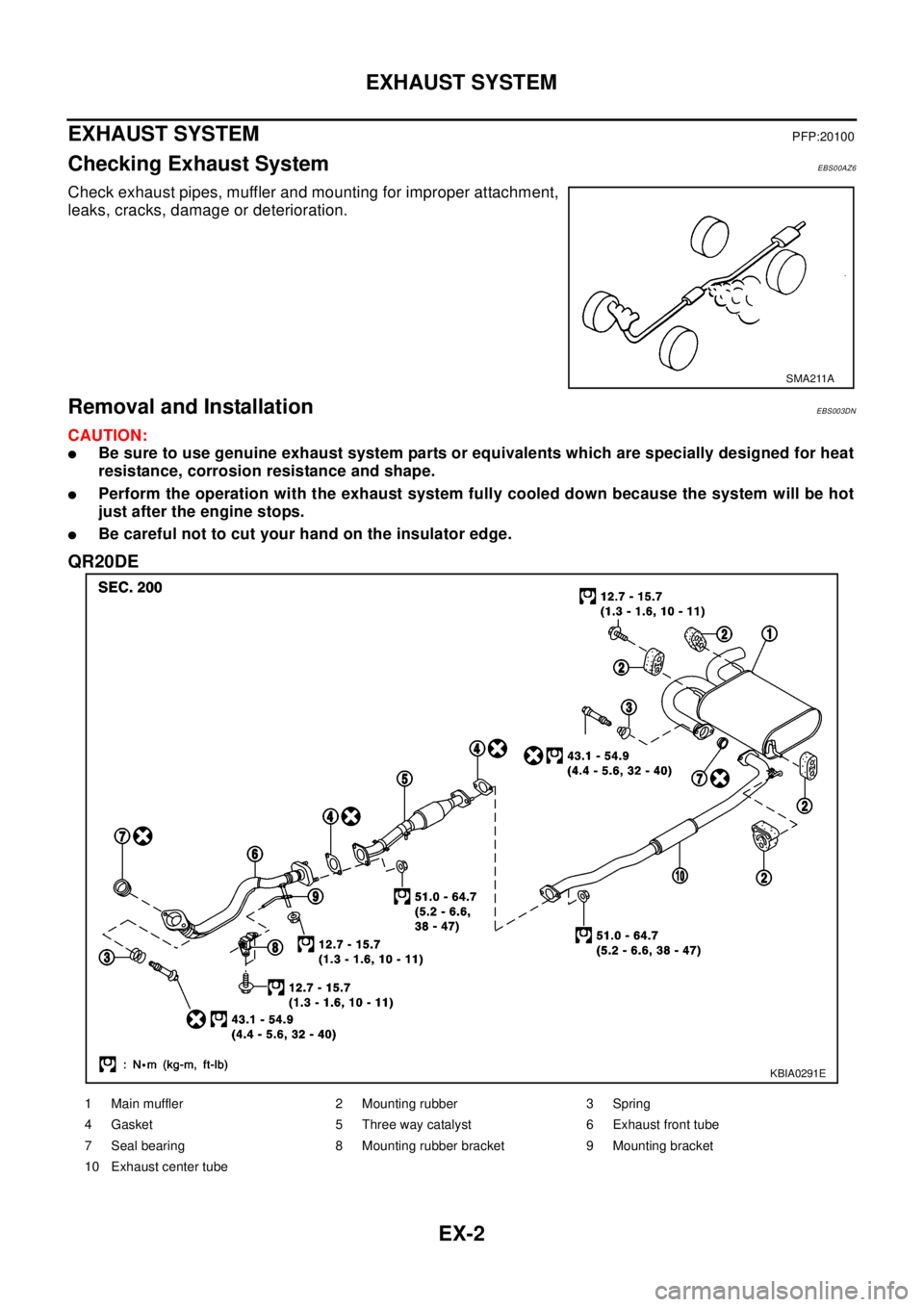
Check exhaust pipes, muffler and mounting for improper attachment,
leaks, cracks, damage or deterioration.
Removal and InstallationEBS003DN
CAUTION:
lBe sure to use genuine exhaust system parts or equivalents which are specially designed for heat
resistance, corrosion resistance and shape.
lPerform the operation with the exhaust system fully cooled down because the system will be hot
just after the engine stops.
lBe careful not to cut your hand on the insulator edge.
QR20DE
SMA211A
KBIA0291E
1 Main muffler 2 Mounting rubber 3 Spring
4 Gasket 5 Three way catalyst 6 Exhaust front tube
7 Seal bearing 8 Mounting rubber bracket 9 Mounting bracket
10 Exhaust center tube
Page 2193 of 3066
EXHAUST SYSTEM
EX-3
C
D
E
F
G
H
I
J
K
L
MA
EX
YD22DDTI
RREMOVAL
Separate each connection as necessity.
INSTALLATION
Install in the reverse order of removal paying attention to the following.
lIf the insulator is badly deformed, repair or replace it. If deposits such as mud pile up on the insulator,
remove them.
lWhen installing the insulator avoid large gaps or interference between the insulator and each exhaust
pipe.
lRemove deposits and left over gasket material from the sealing surface of each connection. Connect
them securely to avoid gas leakage.
lTemporarily tighten the exhaust manifold side mounting nuts and the vehicle side mounting bolts. Check
each part for unusual interference, and then tighten them to the specified torque.
lWhen installing each mounting rubber, avoid twisting or unusual extension in up/down and right/left direc-
tions.
lInstall the seal bearings at front exhaust tube and main muffler as follows.
CAUTION:
Do not mix the bolt and spring for seal bearing as the dimension is different for each seal bearing.
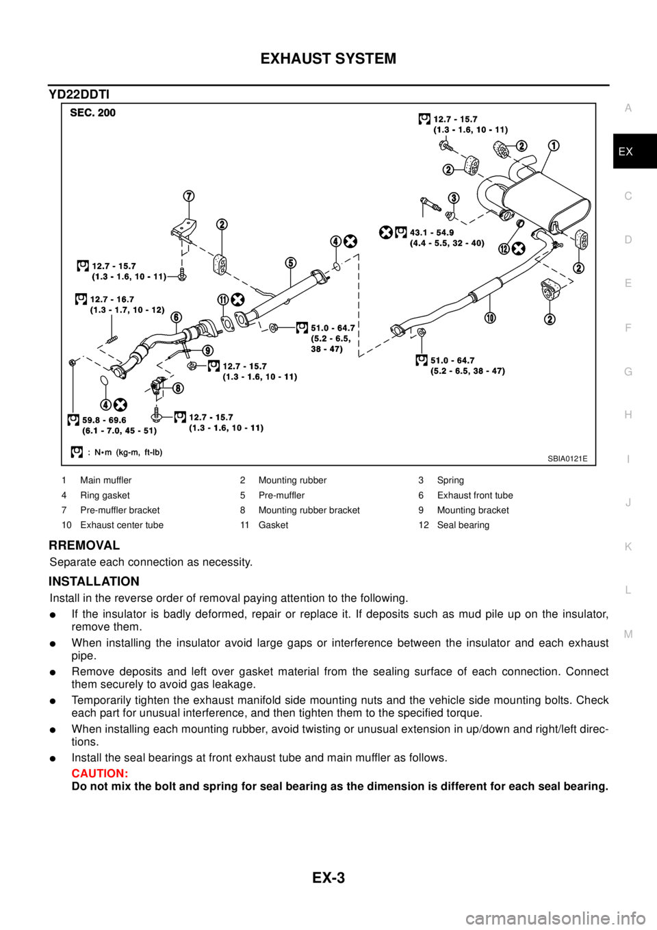
SBIA0121E
1 Main muffler 2 Mounting rubber 3 Spring
4 Ring gasket 5 Pre-muffler 6 Exhaust front tube
7 Pre-muffler bracket 8 Mounting rubber bracket 9 Mounting bracket
10 Exhaust center tube 11 Gasket 12 Seal bearing
Page 2194 of 3066
EX-4
EXHAUST SYSTEM
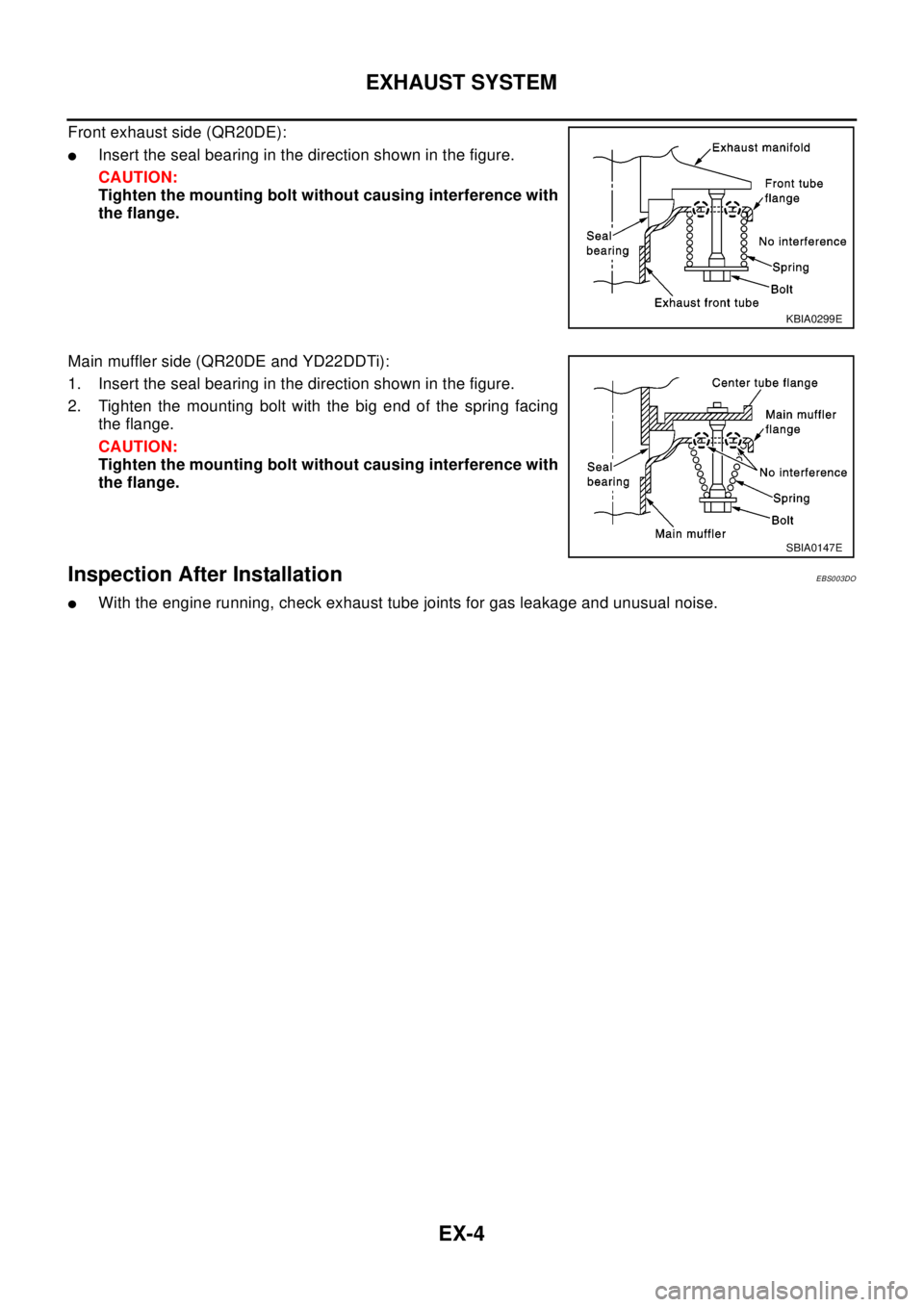
Front exhaust side (QR20DE):
lInsert the seal bearing in the direction shown in the figure.
CAUTION:
Tighten the mounting bolt without causing interference with
the flange.
Main muffler side (QR20DE and YD22DDTi):
1. Insert the seal bearing in the direction shown in the figure.
2. Tighten the mounting bolt with the big end of the spring facing
the flange.
CAUTION:
Tighten the mounting bolt without causing interference with
the flange.
Inspection After InstallationEBS003DO
lWith the engine running, check exhaust tube joints for gas leakage and unusual noise.
KBIA0299E
SBIA0147E
Page 2195 of 3066
SERVICE DATA AND SPECIFICATIONS (SDS)
EX-5
C
D
E
F
G
H
I
J
K
L
MA
EX
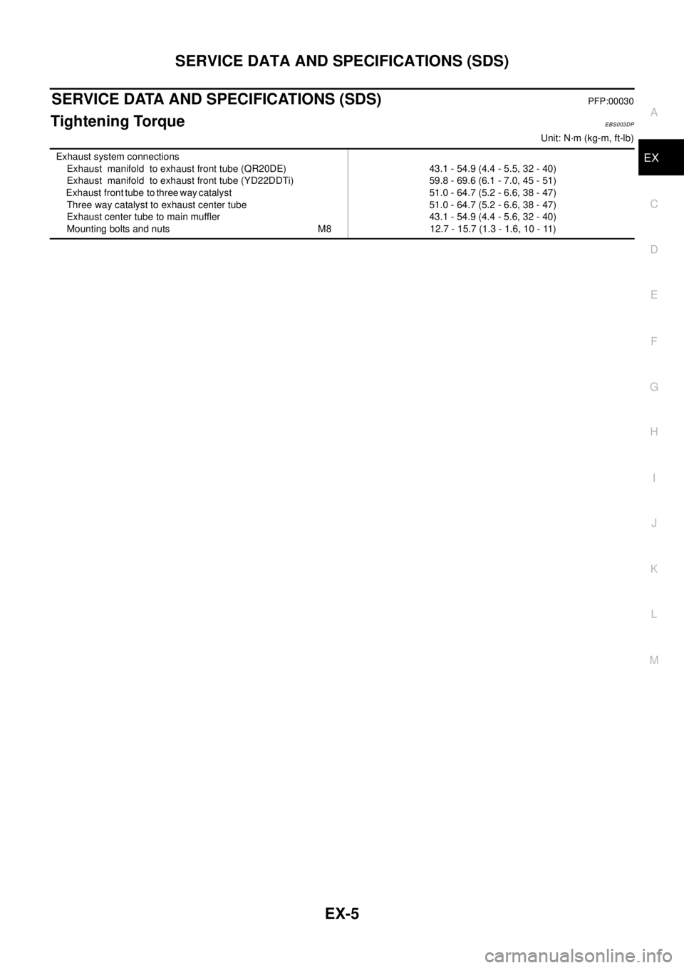
SERVICE DATA AND SPECIFICATIONS (SDS)PFP:00030
Tightening TorqueEBS003DP
Unit: N·m (kg-m, ft-lb)
Exhaust system connections
Exhaust manifold to exhaust front tube (QR20DE)
Exhaust manifold to exhaust front tube (YD22DDTi)
Exhaust front tube to three way catalyst
Three way catalyst to exhaust center tube
Exhaust center tube to main muffler
Mounting bolts and nuts M843.1 - 54.9 (4.4 - 5.5, 32 - 40)
59.8 - 69.6 (6.1 - 7.0, 45 - 51)
51.0 - 64.7 (5.2 - 6.6, 38 - 47)
51.0 - 64.7 (5.2 - 6.6, 38 - 47)
43.1 - 54.9 (4.4 - 5.6, 32 - 40)
12.7 - 15.7 (1.3 - 1.6, 10 - 11)
Page 2196 of 3066

EX-6
SERVICE DATA AND SPECIFICATIONS (SDS)
Page 2197 of 3066
FAX-1
FRONT AXLE
D DRIVELINE/AXLE
CONTENTS
C
E
F
G
H
I
J
K
L
M
SECTION
A
B
FA X
FRONT AXLE
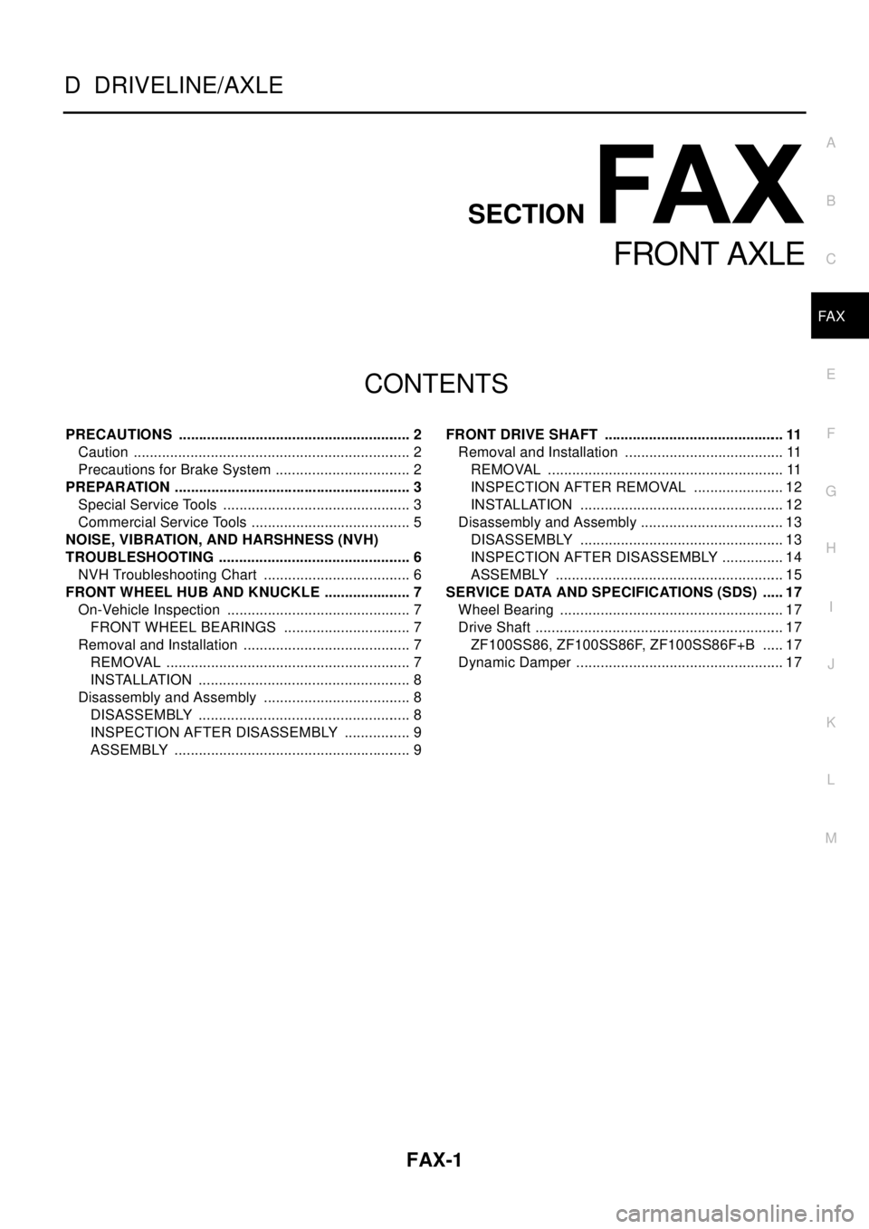
PRECAUTIONS .......................................................... 2
Caution ..................................................................... 2
Precautions for Brake System .................................. 2
PREPARATION ........................................................... 3
Special Service Tools ............................................... 3
Commercial Service Tools ........................................ 5
NOISE, VIBRATION, AND HARSHNESS (NVH)
TROUBLESHOOTING ................................................ 6
NVH Troubleshooting Chart ..................................... 6
FRONT WHEEL HUB AND KNUCKLE ...................... 7
On-Vehicle Inspection .............................................. 7
FRONT WHEEL BEARINGS ................................ 7
Removal and Installation .......................................... 7
REMOVAL ............................................................. 7
INSTALLATION ..................................................... 8
Disassembly and Assembly ..................................... 8
DISASSEMBLY ..................................................... 8
INSPECTION AFTER DISASSEMBLY ................. 9
ASSEMBLY ........................................................... 9FRONT DRIVE SHAFT ............................................. 11
Removal and Installation ........................................ 11
REMOVAL ........................................................... 11
INSPECTION AFTER REMOVAL ....................... 12
INSTALLATION ................................................... 12
Disassembly and Assembly .................................... 13
DISASSEMBLY ................................................... 13
INSPECTION AFTER DISASSEMBLY ................ 14
ASSEMBLY ......................................................... 15
SERVICE DATA AND SPECIFICATIONS (SDS) ...... 17
Wheel Bearing ........................................................ 17
Drive Shaft .............................................................. 17
ZF100SS86, ZF100SS86F, ZF100SS86F+B ...... 17
Dynamic Damper .................................................... 17
Page 2198 of 3066
FAX-2
PRECAUTIONS
PRECAUTIONS
PFP:00001
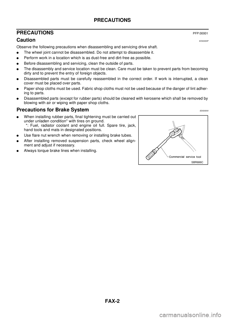
CautionEDS0005P
Observe the following precautions when disassembling and servicing drive shaft.
lThe wheel joint cannot be disassembled. Do not attempt to disassemble it.
lPerform work in a location which is as dust-free and dirt-free as possible.
lBefore disassembling and servicing, clean the outside of parts.
lThe disassembly and service location must be clean. Care must be taken to prevent parts from becoming
dirty and to prevent the entry of foreign objects.
lDisassembled parts must be carefully reassembled in the correct order. If work is interrupted, a clean
cover must be placed over parts.
lPaper shop cloths must be used. Fabric shop cloths must not be used because of the danger of lint adher-
ing to parts.
lDisassembled parts (except for rubber parts) should be cleaned with kerosene which shall be removed by
blowing with air or wiping with paper shop cloths.
Precautions for Brake SystemEDS0 00 I0
lWhen installing rubber parts, final tightening must be carried out
under unladen condition* with tires on ground.
*: Fuel, radiator coolant and engine oil full. Spare tire, jack,
hand tools and mats in designated positions.
lUse flare nut wrench when removing or installing brake tubes.
lAfter installing removed suspension parts, check wheel align-
ment and adjust if necessary.
lAlways torque brake lines when installing.
SBR686C
Page 2199 of 3066
PREPARATION
FAX-3
C
E
F
G
H
I
J
K
L
MA
B
FA X
PREPARATIONPFP:00002
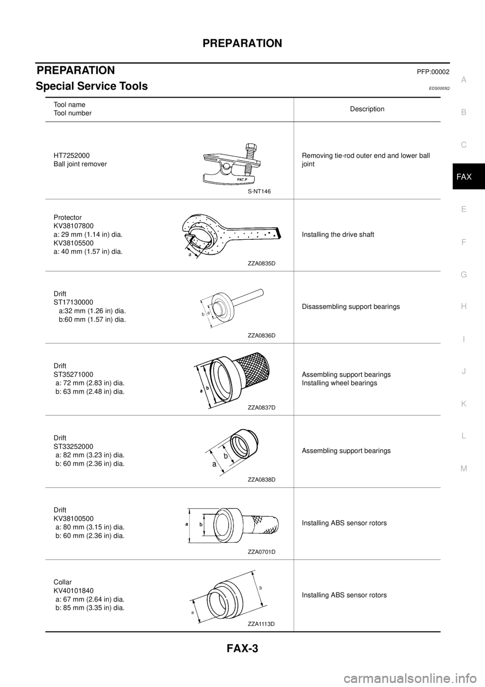
Special Service ToolsEDS0005Q
To o l n a m e
Tool numberDescription
HT7252000
Ball joint removerRemoving tie-rod outer end and lower ball
joint
Protector
KV38107800
a: 29 mm (1.14 in) dia.
KV38105500
a: 40 mm (1.57 in) dia.Installing the drive shaft
Drift
ST17130000
a:32 mm (1.26 in) dia.
b:60 mm (1.57 in) dia.Disassembling support bearings
Drift
ST35271000
a: 72 mm (2.83 in) dia.
b: 63 mm (2.48 in) dia.Assembling support bearings
Installing wheel bearings
Drift
ST33252000
a: 82 mm (3.23 in) dia.
b: 60 mm (2.36 in) dia.Assembling support bearings
Drift
KV38100500
a: 80 mm (3.15 in) dia.
b: 60 mm (2.36 in) dia.Installing ABS sensor rotors
Collar
KV40101840
a: 67 mm (2.64 in) dia.
b: 85 mm (3.35 in) dia.Installing ABS sensor rotors
S-NT146
ZZA0835D
ZZA0836D
ZZA0837D
ZZA0838D
ZZA0701D
ZZA1113D
Page 2200 of 3066
FAX-4
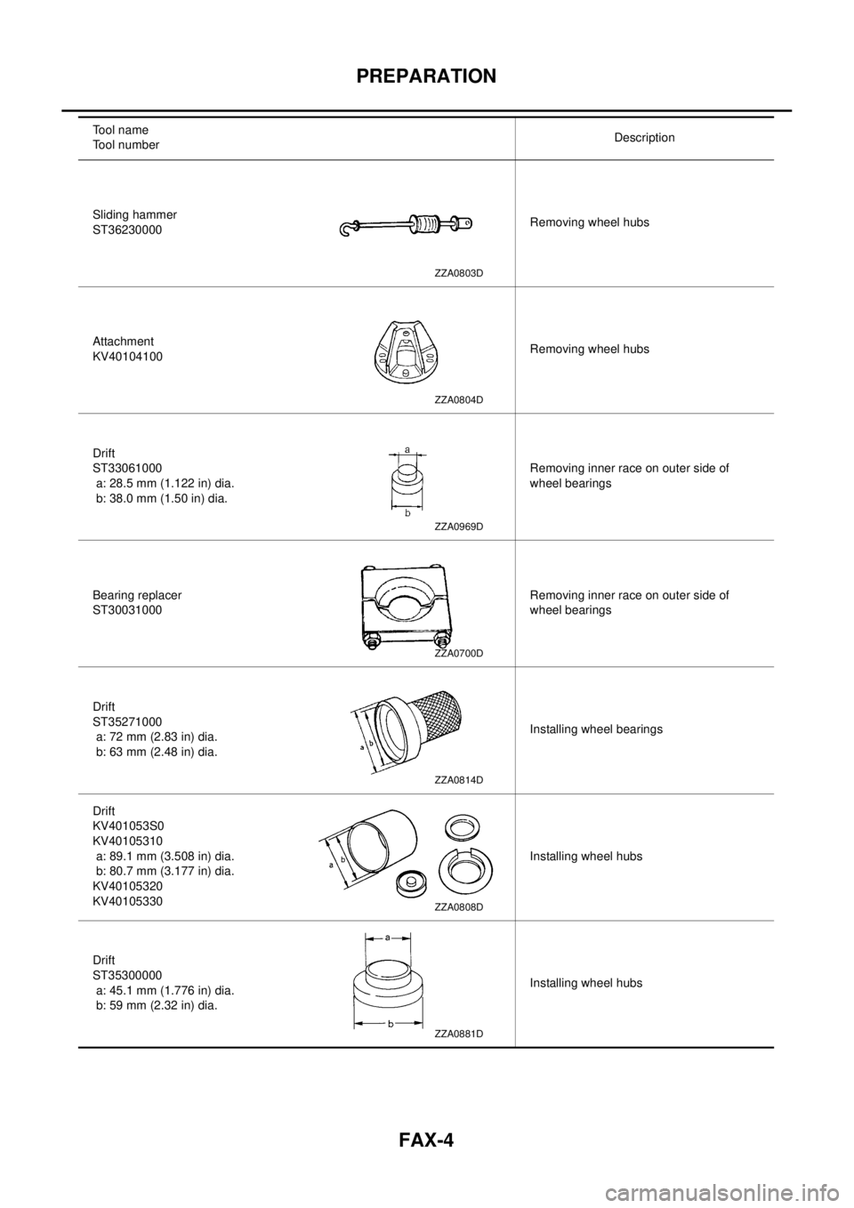
PREPARATION
Sliding hammer
ST36230000Removing wheel hubs
Attachment
KV40104100Removing wheel hubs
Drift
ST33061000
a: 28.5 mm (1.122 in) dia.
b: 38.0 mm (1.50 in) dia.Removing inner race on outer side of
wheel bearings
Bearing replacer
ST30031000Removing inner race on outer side of
wheel bearings
Drift
ST35271000
a: 72 mm (2.83 in) dia.
b: 63 mm (2.48 in) dia.Installing wheel bearings
Drift
KV401053S0
KV40105310
a: 89.1 mm (3.508 in) dia.
b: 80.7 mm (3.177 in) dia.
KV40105320
KV40105330Installing wheel hubs
Drift
ST35300000
a: 45.1 mm (1.776 in) dia.
b: 59 mm (2.32 in) dia.Installing wheel hubs Tool name
Tool numberDescription
ZZA0803D
ZZA0804D
ZZA0969D
ZZA0700D
ZZA0814D
ZZA0808D
ZZA0881D