PONTIAC FIERO 1988 Service Repair Manual
Manufacturer: PONTIAC, Model Year: 1988, Model line: FIERO, Model: PONTIAC FIERO 1988Pages: 1825, PDF Size: 99.44 MB
Page 371 of 1825
4. Remove bearing cap. The flattened gaging plastic
will be found adhering to either the bearing shell
or journal.
5. On the edge of gaging plastic envelope, there is a
graduated scale which is correlated in
thousandths of a millimetre. Without removing
the gaging plastic, measure its compressed width
(at the widest point) with the graduations on the
gaging plastic envelope. Normally, main bearing
journals wear evenly and are not out-of-round.
However, if
a bearing is being fitted to an
out-of-round (.025mm max.), be sure to fit to the
maximum diameter of the journal: If the bearing
is fitted to the minimum diameter and the journal
is out-of-round
.025mm, interference between the
bearing and journal will result in rapid bearing
failure. If the flattened gaging plastic tapers
toward the middle or ends, there is a difference
in clearance indicating taper, low spot or other
irregularity of the bearing or journal. Be sure to
measure the journal with a micrometer if the
flattened gaging plastic indicates more than
,025mm difference.
6. If the bearing clearance is within specifications,
the bearing insert is satisfactory. If the clearance
is not within specifications, replace the insert.
Always replace both upper and lower inserts as
a unit.
7. A standard,
.016mm and .032mm undersize
bearing may produce the proper clearance. If not,
it will be necessary to regrind the crankshaft
journal for use with the next undersize bearing.
After selecting new bearing, recheck clearance.
8. Proceed to the next bearing. After all bearings
have been checked rotate the crankshaft to see
that there is no excessive drag.
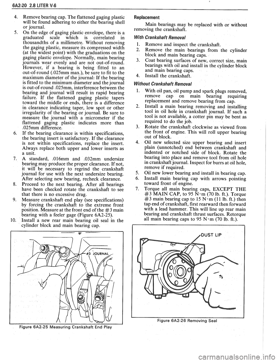
9. Measure crankshaft end play (see specifications)
by forcing the crankshaft to the extreme front
position. Measure at the front end of the
#3 main
bearing with a feeler gage (Figure 6A2-25).
10. Install a new rear main bearing oil seal in the
cylinder block and main bearing cap.
Figure 6A2-25 Measuring Crankshaft End Play
Replacement
Main bearings may be replaced with or without
removing the crankshaft.
With Crankshaft Removal
1. Remove and inspect the crankshaft.
2. Remove the main bearings from the cylinder
block and main bearing caps.
3. Coat bearing surfaces of new, correct size, main
bearings with oil and install in the cylinder block
and main bearing caps.
4. Install the crankshaft.
Without Crankshaft Removal
With oil pan, oil pump and spark plugs removed,
remove cap on main bearing requiring
replacement and remove bearing from cap.
Install a main bearing removing and installing
tool in oil hole in crankshaft journal. If such a
tool is not available, a cotter pin may be bent as
required to do the job.
Rotate the crankshaft clockwise as viewed from
the front of engine. This will roll upper bearing
out of block.
Oil new selected size upper bearing and insert
plain (unnotched) end between crankshaft and
indented or notched side of block. Rotate the
bearing into place and remove tool from oil hole
in crankshaft journal. Inspect for burrs at oil hole,
remove if required.
Oil new lower bearing and install in bearing cap.
Install main bearing cap with arrows pointing
toward front of engine.
Torque all main bearing caps, EXCEPT THE
#3 MAIN CAP, to 95 N.m (70 lb. ft.). Torque
# 3 main bearing cap to 15 N m (1 1 lb. ft.) then
tap end of crankshaft, first rearward then forward
with a lead hammer. This will line up rear main
bearing and crankshaft thrust surfaces.
Retorque
all main bearing caps to 95 N.m (70 Ib. ft.).
1 /DUST LIP
Figure 6A2-26 Removing Seal
Page 372 of 1825
2.8 LITER V-6 6A2-21
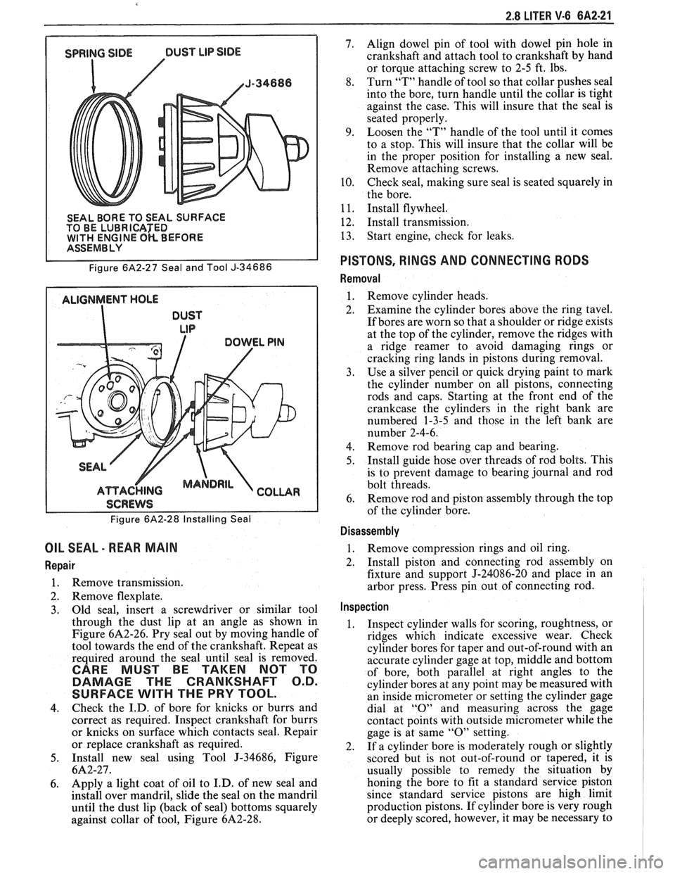
SEAL BORE TO SEAL SURFACE
TO BE LUBRICATED
WlTH ENGINE OK BEFORE I ASSEMBLY
Figure
6A2-27 Seal and Tool J-34686
ALIGNMENT HOLE
DUST
LIP
I SCREWS I
Figure 6A2-28 Installing Seal
OIL SEAL - REAR MAIN
Repair
1. Remove transmission.
2. Remove flexplate.
3. Old
seal, insert a screwdriver or similar tool
through the dust lip at an angle as shown in
Figure
6A2-26. Pry seal out by moving handle of
tool towards the end of the crankshaft. Repeat as
required around the seal until seal is removed.
CARE MUST BE TAKEN NOT TO
DAMAGE THE CRANKSHAFT O.D.
SURFACE
WlTH THE PRY TOOL.
4. Check
the I.D. of bore for knicks or burrs and
correct as required. Inspect crankshaft for burrs
or knicks on surface which contacts seal. Repair
or replace crankshaft as required.
5. Install new seal using Tool J-34686, Figure
6A2-27.
6. Apply a
light coat of oil to I.D. of new seal and
install over mandril, slide the seal on the mandril
until the dust lip (back of seal) bottoms squarely
against collar of tool, Figure
6A2-28.
7. Align dowel pin of tool with dowel pin hole in
crankshaft and attach tool to crankshaft by hand
or torque attaching screw to 2-5 ft. lbs.
8. Turn
"T" handle of tool so that collar pushes seal
into the bore, turn handle until the collar is tight
against the case. This will insure that the seal is
seated properly.
9. Loosen the "T" handle of the tool until it comes
to a stop. This will insure that the collar will be
in the proper position for installing a new seal.
Remove attaching screws.
10. Check seal,
making sure seal is seated squarely in
the bore.
1
1. Install flywheel.
12. Install transmission.
13. Start
engine, check for leaks.
PISTONS, RINGS AND CONNECTING RODS
Removal
1. Remove cylinder heads.
2. Examine the cylinder bores above the ring tavel.
If bores are worn so that a shoulder or ridge exists
at the top of the cylinder, remove the ridges with
a ridge reamer to avoid damaging rings or
cracking ring lands in pistons during removal.
3. Use a silver pencil or quick drying paint to mark
the cylinder number on all pistons, connecting
rods and caps. Starting at the front end of the
crankcase the cylinders in the right bank are
numbered 1-3-5 and those in the left bank are
number 2-4-6.
4. Remove rod bearing
cap and bearing.
5. Install
guide hose over threads of rod bolts. This
is to prevent damage to bearing journal and rod
bolt threads.
6. Remove rod
and piston assembly through the top
of the cylinder bore.
Disassembly
1. Remove compression rings
and oil ring.
2. Install piston and connecting rod assembly on
fixture and support J-24086-20 and place in an
arbor press. Press pin out of connecting rod.
Inspection
1. Inspect cylinder walls for scoring, roughtness, or
ridges which indicate excessive wear. Check
cylinder bores for taper and out-of-round with an
accurate cylinder gage at top, middle and bottom
of bore, both parallel at right angles to the
cylinder bores at any point may be measured with
an inside micrometer or setting the cylinder gage
dial at
"0" and measuring across the gage
contact points with outside micrometer while the
gage is at same
"0" setting.
2. If a cylinder bore is moderately rough or slightly
scored but is not out-of-round or tapered, it is
usually possible to remedy the situation by
honing the bore to fit a standard service piston
since standard service pistons are high limit
production pistons. If cylinder bore is very rough
or deeply scored, however, it may be necessary to
Page 373 of 1825
rebore the cylinder to fit an oversize piston in
order to insure satisfactory results.
3. If cylinder bore is tapered 0. lmm or more or is
out-of-round
O.lmm or more, it is advisable to
rebore for the smallest possible oversize piston
and rings. Below these limits, the cylinder bore
can be trued up with honing.
4. Clean carbon from piston surfaces and under side
of piston heads. Clean carbon from ring grooves
with suitable tool and remove any gum or varnish
from piston skirts with suitable solvent.
5. Carefully examine pistons for
rough or scored
surfaces; cracks in skirt or head; cracked or
broken ring lands; chipped or uneven wearing
pistons would cause rings to seat improperly or
have excessive clearance in ring grooves.
Damaged or faulty pistons should be replaced.
The pistons are cam ground, which means that
the diameter at a right angle to the wrist pin is
greater than the diameter parallel to the wrist pin.
When a piston is checked for size, it must be done
at points 90" to the piston pin. The piston should
be checked (for fitting purposes) in a plane
through the piston pin centerline.
6. Inspect surfaces of wrist pins and check for wear
by measuring worn or unworn surfaces with
micrometers. Occasionally pins will be found
tight due to gum or varnish deposits. This may be
corrected by removing the deposit with a suitable
solvent. If piston bosses are worn out-of-round or
oversize, the piston and pin assembly must be
replaced. Oversize pins are not practical due to
the pin being a press fit in the connecting rod.
Piston pins must fit the piston with an easy finger
push at 70°F (21°C)
(.0065 to .0091mm
clearance).
7. Examine all piston rings for scores, chips or
cracks. Check compression rings for tension by
comparing with new rings. Check gap of
compression rings by placing rings in bore at
bottom of ring travel. Measure gap with feeler
gage. Gap should be between
0.25mm and 0.
50mm. If gaps are excessive (over 0.50mm) it
indicates the rings have worn considerably and
should be replaced. Bore wear should be checked
before rings are replaced,
. l25mm bore wear will
result in
.39mm increase in ring gap.
Assembly
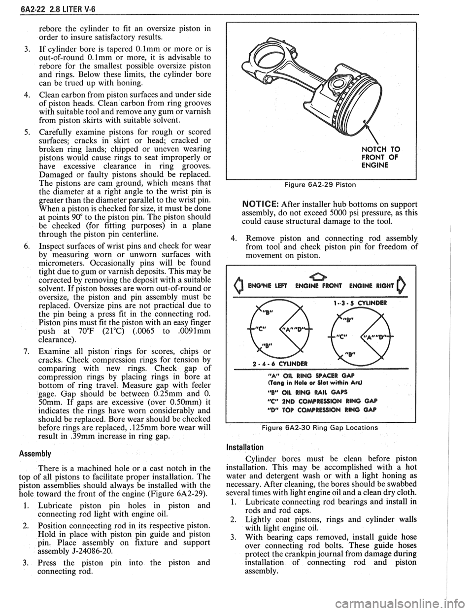
There is a machined hole or a cast notch in the
top of all pistons to facilitate proper installation. The
piston assemblies should always be installed with the
hole toward the front of the engine (Figure
6A2-29).
1. Lubricate piston pin holes in piston and
connecting rod light with engine oil.
2. Position
conncecting rod in its respective piston.
Hold in place with piston pin guide and piston
pin. Place assembly on fixture and support
assembly
J-24086-20.
3. Press the piston pin into the piston and
connecting rod.
NOTCH TO
FRONT OF
ENGINE
Figure 6A2-29 Piston
NOTICE: After installer hub bottoms on support
assembly, do not exceed 5000 psi pressure, as this
could cause structural damage to the tool.
4. Remove piston and connecting rod assembly
from tool and check piston pin for freedom of
movement on piston.
0 Emj@NE Lm ENGINE IRON1 EWINI llWl 0
2 - 1 - 6 CYLINDER
"A" OIL
RING SACER CAP (Tang in Hola w Slot wihin Ad
"B" 011 RING MIL GArs
"C" 1ND COMPRESSION RIM GAB
"DM TOP COAarRESSlON RING GAP
Figure 6A2-30 Ring Gap Locations I
I
Installation I
Cylinder bores must be clean before piston
installation. This may be accomplished with a hot
water and detergent wash or with a light honing as
necessary. After cleaning, the bores should be swabbed
several times with light engine oil and a clean dry cloth.
1. Lubricate connecting rod bearings and install in
rods and rod caps.
2. Lightly coat pistons, rings and cylinder walls
with light engine oil.
3. With bearing caps removed, install guide hose
over connecting rod bolts. These guide hoses
protect the
crankpin journal from damage during
installation of connecting rod and piston
assembly.
Page 374 of 1825
2.8 LITER V-6 8A2-23
4. Make sure the gap in the oil ring rails are in "up"
position toward center of engine and the gaps of
the compression rings are positioned as shown in
Figure
6A2-30.
5. Install each connecting rod and piston assembly
in its respective bore. Install with connecting rod
bearing tang slots on side opposite camshaft. Use
Tool J-8037 or J-8910 to compress the rings.
Guide the connecting rod into place on the
crankshaft journal.
Use a hammer handle and light blows to install
the piston into the bore. Hold the ring
compressor firmly against the cylinder block
until all piston rings have entered the cylinder
bore.
6. Install the bearing caps and torque nuts to
specifications. If bearing replacement is required
refer to "Connecting Rod Bearings".
Be sure to install new pistons in the same
cylinders for which they were fitted, and used
pistons in the same cylinder from which they
were removed. Each connecting rod and bearing
cap should be marked, beginning at the front of
the engine.
On V-6 engines, 1,3 and 5 are in the right bank
and 2,
4 and 6 are in the left bank. The numbers
on the connecting rod and bearing cap must be on
the same side when installed in the cylinder bore.
If a connecting rod is ever transposed from one
block or cylinder to another, new bearings should
be fitted and the connecting rod should be
numbered to correspond with the new cylinder
number.
NOTE. All dlrnenslons are In rn~ll~rnetres.
Figure 6A2-3 1 Service Pistons
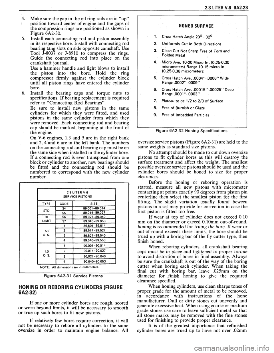
HONING OR REBORING CYLINDERS (FIGURE
6A2-32)
If one or more cylinder bores are rough, scored
or worn beyond limits, it will be necessary to smooth
or true up such bores to fit new pistons.
If relatively few bores require correction, it will
not be necessary to
rebore all cylinders to the same
oversize in order to maintain engine balance. All
HONED SURFACE
1.
Cross Hatch Angle 20' - 32'
2.
Uniformly Cut in Both Directions
3. Clean Cut Not Sharp Free of Torn and
Folded Metal
4. Micro Ave. 10-20 Micro In. (0.254.30 micrometers) Range 10-1 5 micro in.
(0.25-0.38 micrometers)
5. Cross Hatch Ave.
.0004"-.0006" Wide
Range ,0002"-.0009"
6. Cross Hatch Ave. ,0001 5"-.00025" Deep Ranw ,0081 "-.0003"
7. Plateau to be 1/2 to 2/3 of Surface
8. Free of Burnish or Glaze
I 9. Free of Imbedded Particles I
I I Figure 6A2-32 Honing Specifications
oversize service pistons (Figure 6A2-3 1) are held to the
same weights as standard size pistons.
No attempt should be made to cut down oversize
pistons to fit cylinder bores as this will destroy the
surface treatment and affect the weight. The smallest
possible oversize service pistons should be used and the
cylinder bores should be honed to size for proper
clearances.
Before the honing or
reboring operation is
started, measure all new pistons with micrometer
contacting at points exactly 90 degrees from piston pin
centerline then select the smallest piston for the first
fitting. The slight variation usually found
beween
pistons in a set may provide for correction in case the
first piston is fitted too free.
If wear at top of cylinder does not exceed 0.10
mm on the diameter or exceed
0.lOmm out-of-round,
honing is recommended for truing the bore. If wear or
out-of-round exceeds these limits, the bore should be
trued up with a boring bar of the fly cutter type, then
finish honed.
When
reboring cylinders, all crankshaft bearing
caps must be in place and tightened to proper torque
to avoid distortion of bores in final assembly. Always
be sure the crankshaft is out of the way of the boring
cutter when boring each cylinder. When taking the
final cut with boring bar, leave
,025mm on the
diameter for finish honing to give the required
clearance specified.
When honing cylinders, use clean sharps tones of
proper grade for the amount of metal to be removed,
in accordance with instructions of the hone
manufacturer. Dull or dirty stones cut unevenly and
generate excessive heat. When using coarse or medium
grade stones use care to leave sufficient metal so that
all stone marks may be removed with the fine stones
used for finishing to provide proper clearance.
It is of the greatest importance that refinished
cylinder bores are trued up to have not over
.02mm
Page 375 of 1825
6A2-24 2.8 LITER V-6
out-of-round or taper. Each bore must be final honed
to remove all stone or cutter marks and provide a
smooth surface. During final honing, each piston must
be fitted individually to the bore in which it will be
installed and should be marked to insure correct
installation.
After final honing and before the piston is
checked for fit, each cylinder bore must be thoroughly
washed to remove all traces of abrasives and then dried
thoroughly. The dry bore should then be brushed clean
with a power-driven fibre brush. If all traces of the
abrasives are not removed, rapid wear of new pistons
and rings will result.
FITTING PISTONS
1. Remove all rings
from pistons which will be
fitted. It is not necessary to separate rods from
pistons. If an excess amount of varnish or carbon
appears as a ridge at the top of the cylinder,
remove by scraping or sanding.
2. Wipe bores
and pistons clean, removing oil or
other foreign material. Select a piston-rod
assembly for the bore to be fitted (or piston and
pin if a new piston is being fitted) and position
down into the bore with the top of piston down.
The piston should fall free by its own weight
through the bore when when the bottom of the
piston skirt is 12 to 25mm from top of block.
Caution must be used to insure piston is not
damaged when it "falls" through the cylinder. If
it does not, the piston fit is too tight and another
piston should be selected until the piston will slide
freely through the bore without any force being
applied. Mark piston and bore for proper
assembly.
3. After a piston has been slected, which will slide
freely through a bore, it must be determined if
piston fit will be too loose. This is done by placing
a ,060 mm feeler gage for used pistons and a
.050
mm feeler gage for new pistons at least 150mm
long and not over 12mm wide, down into the
same bore with selected piston while holding
feeler to top of the bore.
Position selected piston and feeler down into the
bore until the bottom of the skirt is again 12 to
25 mm from top of block, being sure that the
feeler gage is
90" from the pin. If the piston hangs
on the feeler gage and does not fall free, it
indicates that the piston is correctly fitted to that
respective bore. Mark both piston and bore before
going to the next bore. If the piston fell free
during this check with the
.060mm feeler gage (.
050mm feeler gage for new pistons) then that
particular piston is too small for the bore and a
larger diameter piston will be required.
When checking more than one bore, it is very
possible that what may be a piston too small for one
bore will be a correct fit in another.
PISTON RINGS
When new piston rings are installed without
reboring cylinders, the glazed cylinder walls should be
slightly dulled, but without increasing the bore
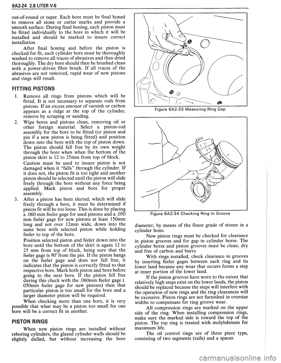
I I Figure 6A2-33 Measuring Ring Gap
i I
I I Figure 6A2-34 Checking Ring In Groove
diameter, by means of the finest grade of stones in a
cylinder hone.
New piston rings must be checked for clearance
in piston grooves and for gap in cylinder bores. The
cylinder bores and piston grooves must be clean, dry
and free of carbon and burrs.
With rings installed, check clearance in grooves
by inserting feeler gages between each ring and its
lower land because any wear that occurs forms a step
at inner portion of the lower land.
If the piston grooves have worn to the extent that
relatively high steps exist on the lower lands, the piston
should be replaced because the steps will interfere with
the operation of new rings and the ring clearances will
be excessive. Piston rings are not furnished in oversize
widths to compensate for ring groove wear.
All compression rings are marked on the upper
side of the ring. When installing compression rings,
make sure the marked side is toward the top of the
piston. The top ring is treated with molybdenum for
maximum life.
The oil control rings are of three piece type,
consisting of two segments (rails) and a spacer.
Page 376 of 1825
2.8 LITER V-6 6A2-25
Fitting
1. Select rings comparable in size to the piston being
used.
2. Slip
the compression ring in the cylinder bore;
then press the ring down into the cylinder bore
about 6mm above ring travel. Be sure ring is
square with cylinder wall.
3. Measure the space or gap between the ends of the
ring with a feeler gage (Figure
6A2-33).
4. If
the gap between the ends of the ring is below
specifications, remove the ring and try another
for fit.
5. Fit each compression ring to the cylinder in
which it is going to be used.
6. If the pistons have not been cleaned and inspected
as previously outlined, do so.
7. Slip the outer surface of the top and second
compression ring into the respective piston ring
groove and roll the ring entirely around the
groove (Figure
6A2-34). If binding occurs at any
point, the cause should be determined. If there is
a ring groove, remove by dressing with a fine cut
file. If the binding is caused by a distorted ring,
check a new ring.
Installation
1. Install oil ring spacer in groove being sure ends
are butted and not overlapped.
2. Hold
spacer ends butted and install lower steel oil
ring rail.
3. Install upper
steel oil ring rail with gap staggered.
4. Flex
the oil ring assembly to make sure ring is
free. If binding occurs, the cause should be
detemined. If caused by ring groove, remove by
dressing groove with a fine cut file. If binding is
caused by a distorted ring, check a new ring.
5. Install second compression ring. Stagger gap
from other rings.
6. Install top compression ring with gap properly
located.
ENGINE ASSEMBLY
Removal
Disconnect battery.
Remove air cleaner.
Remove hood. Drain radiator.
Remove lower radiator hose.
Remove upper fan shroud.
Remove upper radiator hose and coolant
recovery hose.
Remove transmission cooler lines. Remove radiator.
Remove fan assembly.
Remove heater hoses.
Disconnect carburetor linkage, includes cruise
control detent cable.
Remove vacuum brake booster line.
Remove distributor cap and lay wiring aside.
Disconnect necessary wires and hoses.
Remove power steering pump and lay aside. Raise
vehicle.
Remove exhaust pipes at exhaust manifold.
Remove dust cover.
Remove converter bolts.
Disconnect starter wires.
Remove bell housing bolts.
Remove motor mount through bolts.
Disconnect fuel lines at fuel pump.
Lower vehicle. Support transmission.
Remove
A.I.R./Converter pipes bracket.
Remove engine, include removing wire from
bracket at rear left of engine.
Installation
Position engine assembly in vehicle.
Attach motor mount to engine brackets and
lower engine in place.
Remove engine lifting device.
Remove transmission floor jack.
Raise vehicle on hoist.
Install mount "through" bolts. Torque to
specifications.
Install bell housing bolts. Torque to
specifications.
On vehicles with automatic transmission, install
converter to flywheel attaching bolts. Torque to
specifications.
Install flywheel splash shield of conveter housing
cover as applicable. Torque attaching bolts to
specifications.
Install starter wires.
Connect fuel lines.
Connect exhaust pipe at manifold.
Lower vehicle on hoist.
Reinstall power steering pump, if so equipped.
Connect necessary wires and hoses.
Install radiator and fan shroud and reconnect
radiator and heater hoses.
Fill cooling system.
Fill crankcase with oil. See owner's manual for
specifications.
Install air cleaner.
Install hood.
Connect battery cables.
NOTICE: To avoid possible arcing of battery,
connect positive battery cable first.
22. Start engine, check for leaks and check timing.
CRANKSHAFT
The crankshaft can be removed while the engine
is dissasembled for overhaul, as previously outlined or
without complete disassembly.
Removal
1. With the engine removed from the vehicle,
remove the clutch assembly (if equipped) and
flywheel. Mount engine in stand and clamp
securely.
Page 377 of 1825
6A2-26 2.8 LITER V-6
2. Remove the spark plugs. Installation
3. Remove
crankshaft pulley and torsional damper. 1. Install rear main bearing oil seal in cylinder block
4. Remove oil pan and oil pump. and
rear bearing cap grooves.
5. Remove water pump, crankcase front cover, 2. Lubricate seal with engine oil. Keep oil off
camshaft sprocket and timing chain. parting
line surface.
3. Install main bearings in cylinder block and main
6. Check the connecting rod caps for cylinder
bearing caps then lubricate bearing surface with
number identification. If necessary mark them.
engine oil.
7. Remove the connecting rod caps and
push the
4. 1n;tall crankshaft, being careful not to damage
pistons to top of bores.
bearing surfaces.
8. Remove main bearing caps and lift crankshaft out 5. Recheck bearing clearances using plastigage.
of cylinder block. 6.
Apply a thin coat of anaerobic sealant
# 1052357
9. Remove rear
main bearing oil seal and main or
equivalent to rear of the block mating surface
bearings from cylinder block and main bearing or corresponding
surface or rear main cap only.
caps. Do
not allow sealer on crankshaft or seal.
7. Install main bearing caps with arrow pointing
Cleaning and Inspection toward front of engine.
8. Torque all except
#3 main bearing cap bolts to
1. Wash crankshaft in solvent and dry with
specifications. Torque
#3 main bearing cap bolts
compressed air. to 14-16
N-m (10-12 lbs. ft.) then tap end of
2. Measure
dimensions of main bearing journals and crankshaft, first rearward then forward with a
crankpins with a micrometer for out-of-round, lead
hammer. This will line up rear main bearing
taper or undersize (See Specifications). and crankshaft
thrust surfaces.
Retorque all main
3. Check
crankshaft for run-out by supporting at bearing
cap bolts to specifications.
the front and rear main bearings journals in "V" 9. Measure crankshaft
end play with a feeler gage.
blocks and check at the front and rear Force crankshaft forward and measure clearance
intermediate journals with a dial indicator (See between the front of the
#3 main bearing and
Specifications). crankshaft thrust surface.
4. Replace or recondition the crankshaft if out of 10.
Install flywheel and torque to specifications.
specifications.
SPROCKET OR GEAR REPLACEMENT
Remove crankshaft sprocket using Tool J-5825,
install using Tool J-5590.
GENERAL DATA
TYPE .................................................................................................................................... 60" V-6
DISPLACEMENT
............................................................................................................. 2.8 Liter
RPO
........................................................................................................................................... LB8
BORE ......................................................................................................................................... 89
STROKE
................................... .... ............................................................................................... 76
COMPRESSION RATIO
....................................................................................................... 8.9: 1
FIRING ORDER
.......................................................................................................... 1-2-3-4-5-6
Cylinder Bore
DIAMETER .............................................................................................................. 88.992-88.070
OUT OF ROUND
............................................................................................................. .02 Max.
TAPER-THRUST SIDE
................................................................................................. .02 Max.
Piston
CLEARANCE .................................................................................................................. .O 17-,043
Piston Ring
Page 378 of 1825
COMPRESSION Groove Clearance
............................................................................................................................ Top .030..070
................................................................................ Second .................................... .... .040.. 095
Gap ................................................................................................................................. Top .25..50
............................................................................................................................ Second .25..50
OIL
...................................................................................................... . Groove Clearance 0 199 Max
Gap
................................................................................................................................ 0.51-1.40
Piston Pin
DIAMETER ....................................................................................................... 22.9937-23.0015
........................................................................................................... CLEARANCE .0065-.009 1
FIT IN ROD
..................................................................................................... .0187-. 0515 Press
Camshaft
LIFT
Intake
................................................................................................................................... 6.67
Exhaust
.................................................................................................................................. 6.94
............................................................. ............................ JOURNAL DIAMETER .. 47.44-47.49
............................................................................................. JOURNAL CLEARANCE .026- . 101
Crankshaft
MAIN JOURNAL
Diameter All
67.241-67.265mm
............................................................................................................................. Taper 005 Max .
................................................................................................................ Out of Round 005
Max .
.................................................................................. MAIN BEARING CLEARANCE 04
1-.08 1
................................................................ MAIN THRUST BEARING CLEARANCE .054..084
...................................................................................... CRANKSHAFT END PLAY .06-. 2 1mm
CRANK PIN
Diameter
..................................... ... ......................................................................... 50.784-50.758
............................................................................................................................. Taper 005 Max .
............................................................................................................ Out of Round 005
Max .
.................................................... ROD BEARING CLEARANCE ......................... .. 03 5..095
................................................................................................ ROD SIDE CLEARANCE .16-. 44
Valve System
LIFTER ......................... .. ........................................................................................... Hydraulic
......................................................................................................... ROCKER ARM RATIO 1.5. 1
............................................................................... VALVE LASH 1- 1/2 Turns From Zero Lash
FACE ANGLE
........................................................................................................................... 45"
SEAT ANGLE ......................................................................................................................... 46"
....................................................................................................................... SEAT RUNOUT 05"
SEAT WIDTH
Intake
........................................................................................................................ 1.25-1.50
......................................................................................................................... Exhaust 1.60- 1.90
............................................................... STEM CLEARANCE ..................................... ... .026-. 068
VALVE SPRING
Free Length
......................................................................................................................... 48.5
Pressure N
. m
Closed
....................... .. .......................................................................................... 391 @40
Open
......................................................................................................................... 867 @30
Installed Height
........................................................................................................................ 40
DAMPER
........................................................................................................................... Free Length 47.2
Page 379 of 1825
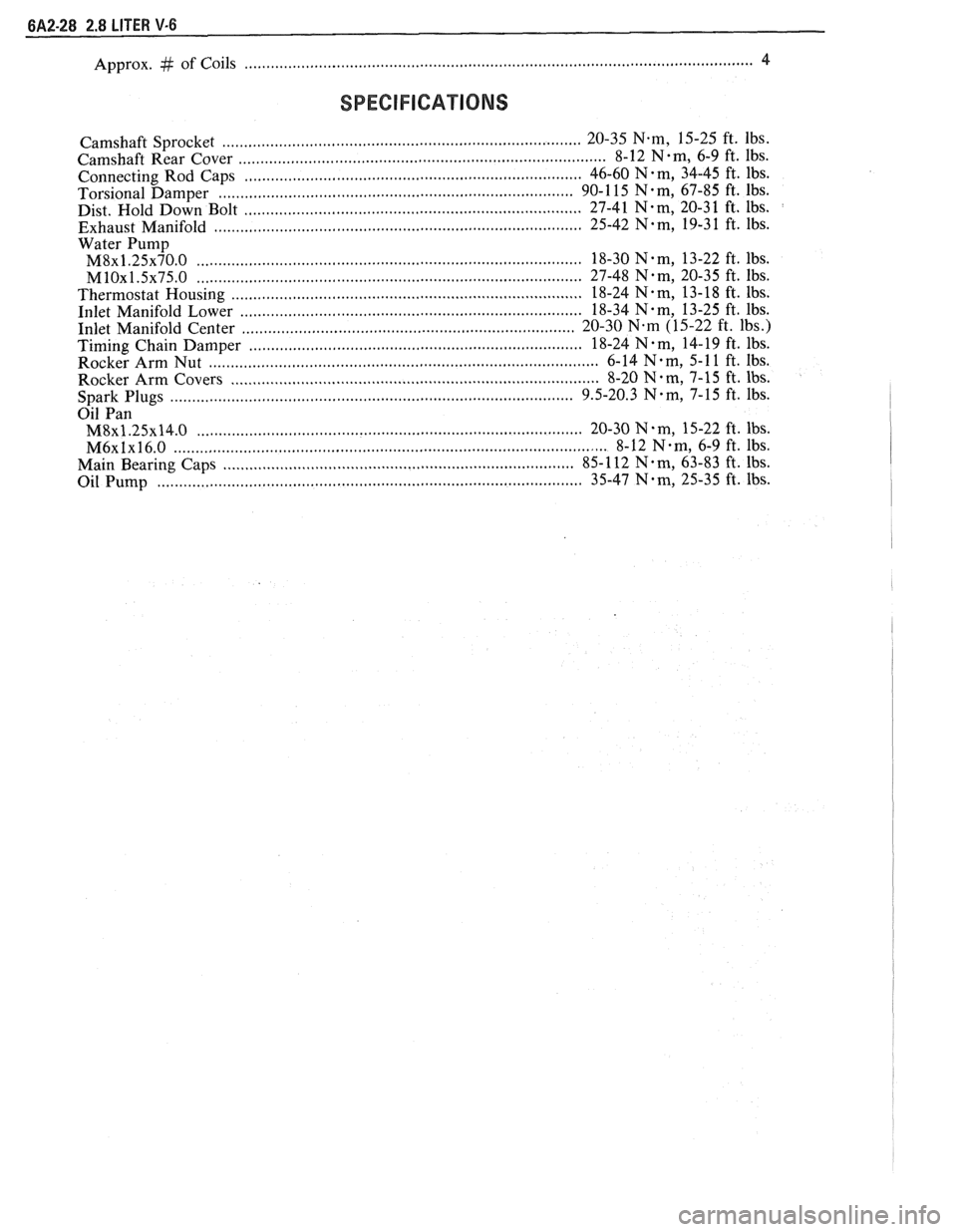
Approx. # of Coils ................................... .... ............................................................................. 4
SPECIFICATIONS
................................................................................ Camshaft Sprocket 20-35 N-m, 15-25
ft. lbs.
................................................................................... Camshaft Rear Cover 8-12 N-m, 6-9 ft. 1bs.
......................................................................... . Connecting Rod Caps 46-60 N m, 34-45
ft. lbs.
............................................................................ Torsional Damper 90-1
15 N-m, 67-85 ft. lbs.
Dist. Hold Down Bolt ..................... ..... ............................................... 27-41 N.m, 20-3 1 ft. lbs.
................................................................................. Exhaust Manifold 25-42 N.m, 19-3 1 ft. lbs.
Water
Pump
M8~1.25~70.0 ........................................................................................ 18-30 N.m, 13-22 ft. lbs.
MlOx1.5x75.0 .......................... .. ........................................................ 27-48 Nem, 20-35 ft. lbs.
Thermostat Housing ........................................................................... 18-24 N-m, 13-18 ft. lbs.
Inlet Manifold Lower
........................................................................... 18-34 N-m, 13-25 ft. lbs.
............................................ ........................ Inlet Manifold Center .. 20-30 N.m (15-22 ft. lbs.) ............................................................................ Timing Chain Damper 18-24
N . m, 14- 19 ft. lbs.
Rocker Arm Nut
........................................................................................ 6-14 N-m, 5-1 1 ft. Ibs.
Rocker Arm Covers
.................................................................................... 8-20 N-m, 7-15 ft. lbs. ........................................................................................ Spark Plugs 9.5-20.3 N-m, 7-15
ft. lbs.
Oil Pan
M8~1.25x14.0 .................................................................................... 20-30 N.m, 15-22 ft. lbs.
M6xlx16.0 ............................................................................................... 8-12 Nem, 6-9 ft. lbs.
................................................................................ Main Bearing Caps 85-
112 N. m, 63-83 ft. lbs.
Oil Pump
............................................................................................. 35-47 Nem, 25-35 ft. lbs.
Page 380 of 1825
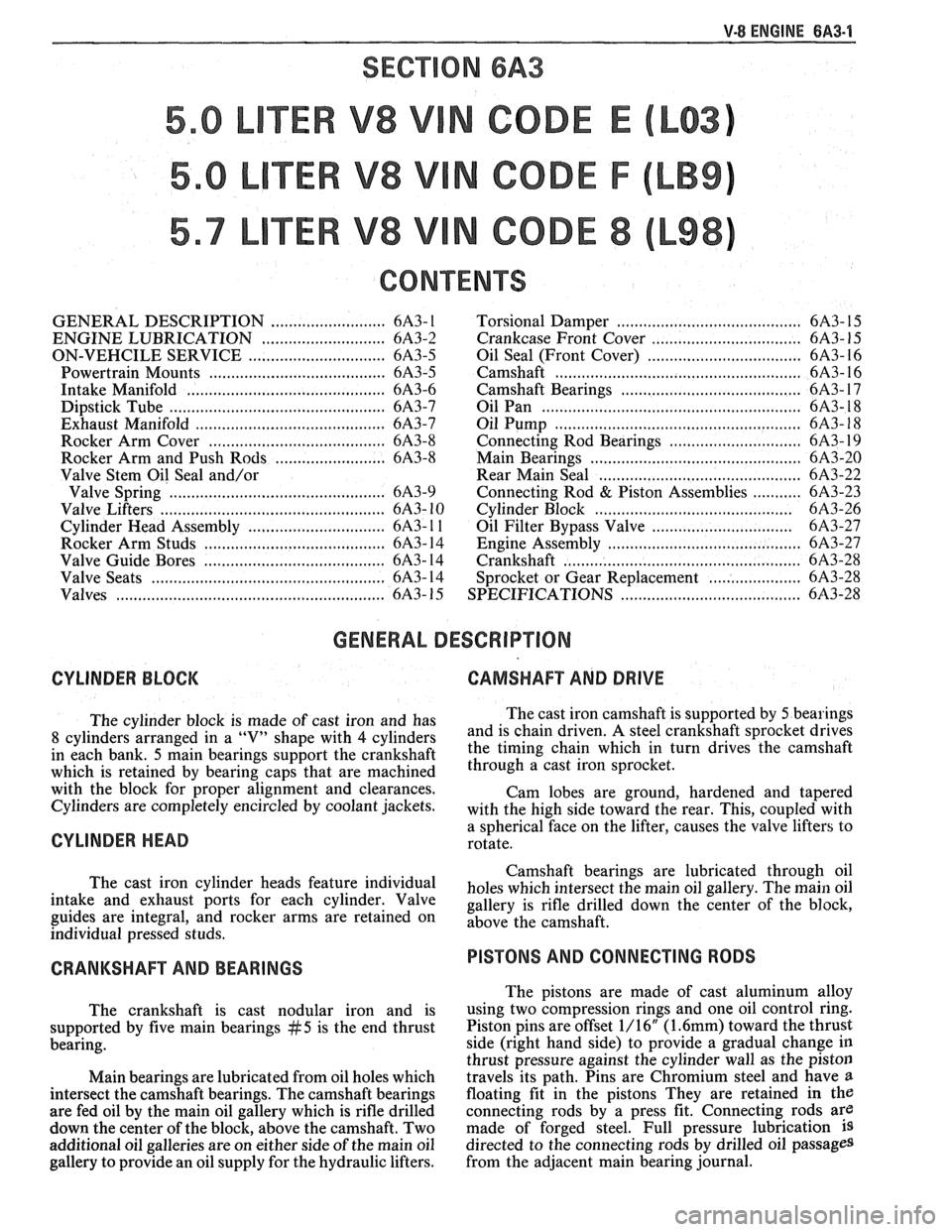
V-8 ENGINE BA3-1
SECVON 6A3
TER V8 V N CODE E
TER V8 V N CODE F
TER V8 V N CODE 8
CONTENTS
GENERAL DESCRIPTION .......................... 6A3- 1
ENGINE LUBRICATION .......................... 6A3-2
ON-VEHCILE SERVICE ............................... 6A3-5
...................................... Powertrain Mounts 6A3-5
Intake Manifold ........................................... 6A3-6
Dipstick Tube .............................................. 6A3-7
Exhaust Manifold ........................................... 6A3-7
........................................ Rocker Arm Cover 6A3-8
Rocker Arm and Push Rods ...................... 6A3-8
Valve Stem Oil Seal and/or
Valve Spring
................................................ 6A3-9
Valve Lifters .................................................. 6A3- 10
............................. Cylinder Head Assembly 6A3- 1 1
...................................... Rocker Arm Studs 6A3- 14
...................................... Valve Guide Bores 6A3- 14
Valve Seats .................................................. 6A3- 14
Valves ........................................................... 6A3- 15
Torsional Damper ........................................ 6A3- 15
.
............................. Crankcase Front Cover .... 6A3- 1 5
Oil Seal (Front Cover) ................................... 6A3- 16
Camshaft ...................................................... 6A3- 16
Camshaft Bearings ............................. .. ....... 6A3- 17
Oil Pan ......................................................... 6A3- 18
..................................................... Oil Pump 6A3- 18
............................. Connecting Rod Bearings 6A3- 19
.............................................. Main Bearings 6A3-20
........................................... Rear Main Seal 6A3-22
........... Connecting Rod & Piston Assemblies 6A3-23
............................................ Cylinder Block 6A3-26
............................... Oil Filter Bypass Valve 6A3-27
.......................................... Engine Assembly 6A3-27
................................................... Crankshaft 6A3-28
..................... Sprocket or Gear Replacement 6A3-28
......................................... SPECIFICATIONS 6A3-28
GENERAL DESCRIPTION
CYLINDER BLOCK CAMSHAFT AND DRIVE
The cylinder block is made of cast iron and has The
cast iron camshaft is supported by 5 bearings
8 cylinders arranged in a "V" shape with 4 cylinders and
is chain driven. A steel crankshaft sprocket drives
in each bank.
5 main bearings support the crankshaft the
timing chain which in turn drives the camshaft
which is retained by bearing caps that are machined through a cast iron 'procket.
with the block for proper alignment and clearances.
Cam lobes are ground, hardened and tapered
Cylinders are completely encircled by coolant Jackets, with the high side toward the rear. This, cou~led with
CYLINDER HEAD a sphericalYface on the lifter, causes the "alve lifters to
rotate.
Camshaft bearings are lubricated through oil
The cast iron cylinder heads feature individual
holes which intersect the main oil gallery. The main oil intake and exhaust Ports for each cylinder. Valve gallery is rifle drilled down the center of the block, guides are integral, and rocker arms are retained on above the individual pressed studs.
CRANKSHAFT AND BEARINGS
The crankshaft is cast nodular iron and is
supported by five main bearings
#5 is the end thrust
bearing.
Main bearings are lubricated from oil holes which
intersect the camshaft bearings. The camshaft bearings
are fed oil by the main oil gallery which is rifle drilled
down the center of the block, above the camshaft. Two
additional oil galleries are on either side of the main oil
gallery to provide an oil supply for the hydraulic lifters.
PISTONS AND CONNECTING RODS
The pistons are made of cast aluminum alloy
using two compression rings and one oil control ring.
Piston pins are offset 1/16"
(1.6mm) toward the thrust
side (right hand side) to provide a gradual change in
thrust pressure against the cylinder wall as the piston
travels its path. Pins are Chromium steel and have
a
floating fit in the pistons They are retained in the
connecting rods by a press fit. Connecting rods are
made of forged steel. Full pressure lubrication
is
directed to the connecting rods by drilled oil passages
from the adjacent main bearing journal.