PONTIAC FIERO 1988 Service Repair Manual
Manufacturer: PONTIAC, Model Year: 1988, Model line: FIERO, Model: PONTIAC FIERO 1988Pages: 1825, PDF Size: 99.44 MB
Page 351 of 1825

Page 352 of 1825
2.8 LITER V-6 BA2-1
TER V-6 V N CODES RPO
CONTENTS
GENERAL DESCRIPTION ........................ 6A2- 1
ENGINE LUBRICATIONS ......................... 6A2- 1
ON-VEHICLE SERVICE ............................. 6A2-7
Powertrain Mounts .................................... 6A2-7
Rocker Arm Cover .................................... 6A2-8
Intake Manifold .......................................... 6A2-9
Exhaust Manifold ................................... 6A2-9
Rocker Arm and Push Rod ....................... 6A2- 10
Valve Mechanism
....................................... 6A2- 10
Valve Stem Oil Seal and/or Valve
Spring
.................... .. .. ... ................... 6A2- 10
Valve Lifters
............................................. 6A2- l l
Cylinder Head ............................................ 6A2- 12
Rocker Arm Studs
.................................... 6A2- 13
Valve Guides
........................................... 6A2- 13
Valve Seats
................................................ 6A2- 14
Valves
......................................................... 6A2- 14
Torsional Damper
..................................... 6A2- 14 Crankcase
Front Cover
.............................. 6A2- 15
Oil Seal (Front Cover)
........................... .... 6A2- 15
Timing Chain
& Sprocket .......................... 6A2- 15
Camshaft
................................................... 6A2- 16
Camshaft Bearings
................................... 6A2- 16
Oil Pan
........................................................ 6A2- 17
Oil Pump
.................................................. 6A2- 18
Connecting Rod Bearings .......................... 6A2- 18
Main Bearings
............................................ 6A2- 19
Oil Seal (Rear Main)
.................................. 6A2-2 1
Pistons, Rings & Connecting Rods ........... 6A2-2 1
Honing or Reboring Cylinders .................. 6A2-23
Fitting Pistons ............................................ 6A2-24
.............................................. Piston Rings 6A2-24
Engine Assembly ...................................... 6A2-25
.................................................. Crankshaft 6A2-25
........................................ Sprocket or Gear 6A2-26
..................................... SPECIFICATIONS 6A2-26
GENERAL DESCRIPTION
CYLINDER BLOCK
The cylinder block is made of alloy cast iron and
has 6 cylinders arranged in a "V" shape with 3
cylinders in each bank. The cylinder banks are set at
a
60" angle from each other.
The right bank cylinders are
1, 3, 5. Cylinders 2,
4, 6 are on the left bank.
Four main bearings support the crankshaft which
is retained by bearing caps that are machined with the
block for proper alignment and clearances.
CYLINDER HEAD
The cast alloy iron cylinder heads have individual
intake and exhaust ports for each cylinder. Valve
guides are integral, and rocker arms are retained on
individual threaded studs.
CRANKSHAFT AND BEARINGS
The crankshaft is cast nodular iron with deep
rolled fillets on all six crankpins and two center main
journals. Four steel backed aluminum bearings are
used, with
#3 bearing being the end-thrust bearing.
CAMSHAFT AND DRIVE
sprocket is also hardened sintered iron, and is pressed
onto the nose of the crankshaft.
A rubber snubber is
used to dampen chain motion.
PISTONS AND CONNECTING RODS
The pistons are cast aluminum with steel struts
using two compression rings and one coil control ring.
The piston pin is offset
1.5mm towards the major
thrust side. This allows a gradual change in thrust
pressure against the cylinder wall as the piston travels
its path. Pins are chromium steel and have a floating
fit in the pistons. They are retained in the connecting
rods by a press fit.
Connecting rods are made of forged steel. Full
pressure lubrication is directed to the connecting rods
by drilled oil passages from the adjacent main bearing
journal.
VALVE TRAIN
A very simple ball pivot-type train is used.
Motion is transmitted from the camshaft through the
hydraulic lifter and push rod to the rocker arm. The
rocker arm
~ivots on its ball and transmits the
camshaft
mot'ion to the valve. The rocker arm ball
locates on a stud, threaded into the head, and is
The camshaft is cast alloy iron with tapered 13. by a nut. The push rod is located by a guide
2mm wide lobes, offset from the lifters and tapered to plate held under the rocker arm stud, assuring that the
provide positive valve lifter rotation. The camshaft is arm Operates in the plane the
support& by four journals and includes a
distributor/oil pump drive gear, and fuel pump INTAKE MANIFOLD - - eccentric.
The intake manifold is a three piece cast
A
3/8" pitch chain drives the camshaft through
aluminum unit. It centrally supports a fuel rail with 6
a hardened sintered iron sprocket. The crankshaft
fuel injectors.
Page 353 of 1825
6A2-2 2.8 LITER V-6
EXHAUST MANIFOLDS
The exhaust manifolds are cast nodular iron.
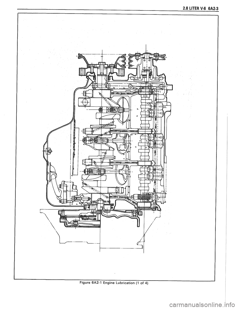
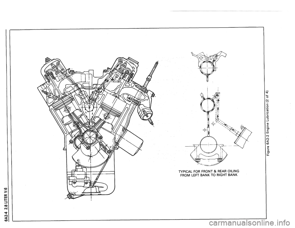
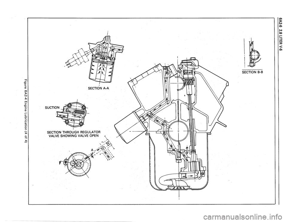
ENGINE LUBRICATION (FIGURES 6A2.1 THRU
6A2-4)
Full pressure lubrication, through a full flow oil
filter is furnished by a gear type oil pump. Oil is drawn
up through the pick up screen and tube and passed
through the pump to the oil filter.
The oil filter is a full flow paper element unit. An
oil filter by-pass is used to ensure adequate oil supply
should the filter develope excessive pressure drop. The
by-pass is designed to open at 69-83
kPa.
From the filter, oil is routed to the main oil
gallery, rifle drilled above the camshaft to the left of the
camshaft centerline. This gallery supplies the left bank
hydraulic lifters with oil. From
the left gallery oil is directed, by means of
interesting passages to the camshaft bearings and right
oil gallery.
The hydraulic lifters pump oil up through the
push rods to the rocker arms. Oil draining back from
the rocker arms is directed, by cast dams which are
part of the crankcase casting, to supply the camshaft
lobes.
The passages supplying oil to the camshaft
bearings also supply the crankshaft main bearings
through intersecting vertical drilled holes. Oil from the
crankshaft main bearings is supplied to the connecting
rod bearings by means of intersecting passages drilled
in the crankshaft.
Oil also drains past specific hydraulic lifter flats
to oil camshaft .lobes directly.
The front cam bearing has a
.25mm deep slot on
its outside diameter to supply oil to the cam sprocket
thrust face.
Page 354 of 1825
Page 355 of 1825
Page 356 of 1825
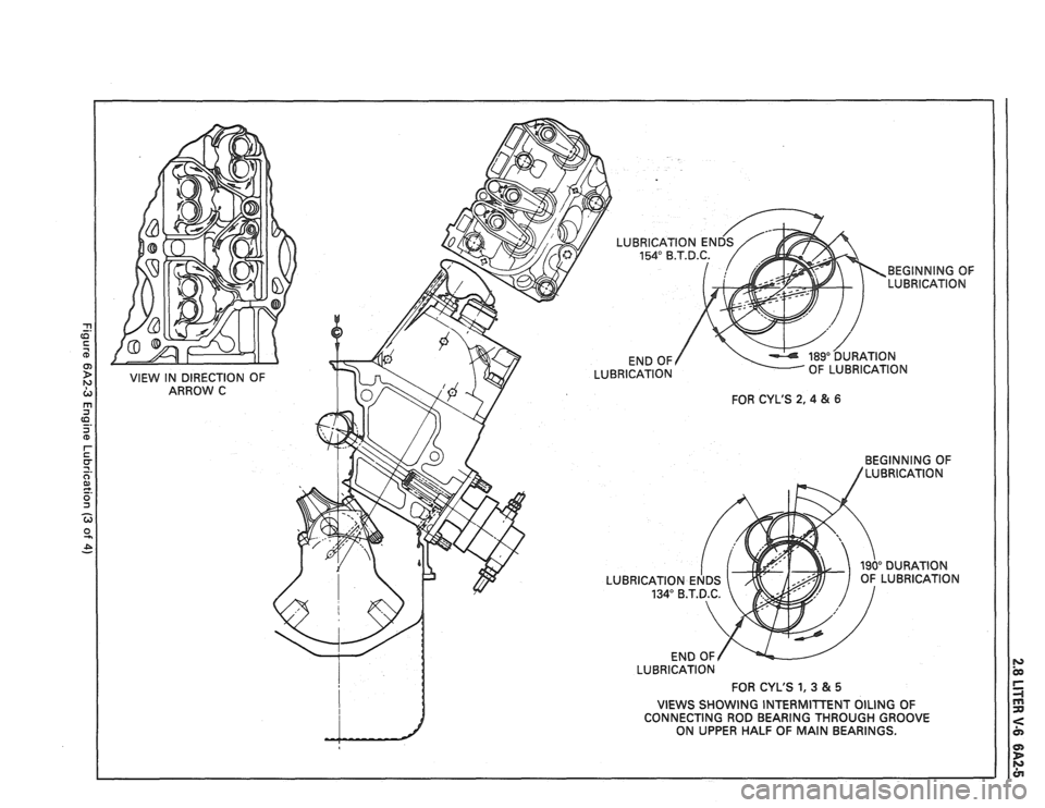
LUBRICATION FOR CYL'S
1,3 &5
VIEWS SHOWING INTERMInENT OILING OF
CONNECTING ROD BEARING THROUGH GROOVE
ON UPPER HALF
OF MAIN BEARINGS.
Page 357 of 1825
SECTION B-B
Page 358 of 1825
2.8 LITER V-6 6A2-7
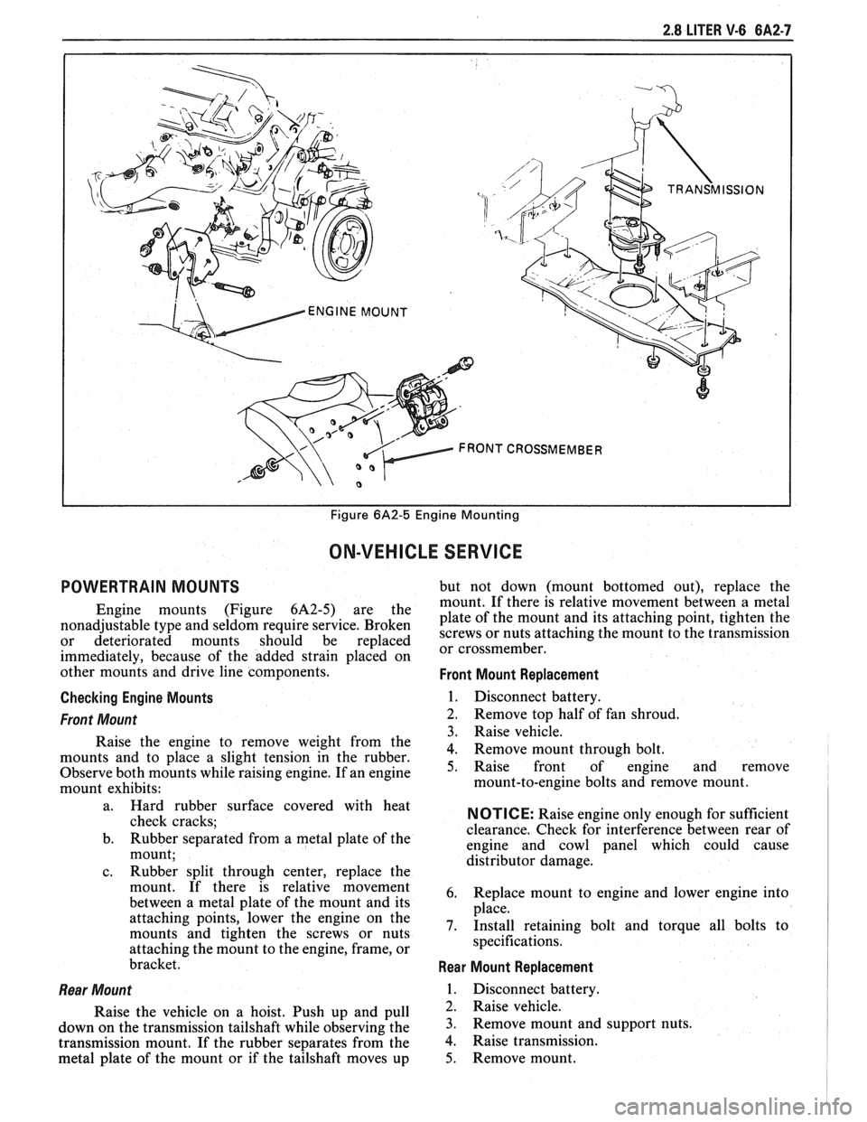
I I Figure 6A2-5 Engine Mounting
ON-VEHICLE SERVICE
POWERTRAIN MOUNTS but not down (mount bottomed out), replace the
mount. If there is relative movement between a metal
Engine mounts (Figure 6A2-5) are the plate of the mount and its attaching point, tighten the nonadjustable type and seldom require service. Broken screws or nuts attaching the mount to the transmission or deteriorated mounts should be replaced or cross member^
immediately, because of the added strain placed on
other mounts and drive line components.
Front Mount Replacement
Checking Engine Mounts
1. Disconnect battery.
Front Mount 2. Remove top half of fan shroud.
3. Raise vehicle.
Raise the engine to remove weight from the
4. Remove mount through bolt. mounts and to place a slight tension in the rubber.
Observe both mounts while raising engine. If an engine 5. Raise front of engine and remove
mount exhibits: mount-to-engine
bolts and remove mount.
l
a. Hard rubber surface covered with heat
check cracks;
b. Rubber separated from a metal plate
of the
mount;
c. Rubber split through center, replace the
mount. If there is relative movement
between a metal plate of the mount and its
attaching points, lower the engine on the
mounts and tighten the screws or nuts
attaching the mount to the engine, frame, or
bracket.
Rear Mount
Raise the vehicle on a hoist. Push up and pull
down on the transmission tailshaft while observing the
transmission mount. If the rubber separates from the
metal plate of the mount or if the tailshaft moves up
NOTICE: Raise engine only enough for sufficient
clearance. Check for interference between rear of
engine and cowl panel which could cause
distributor damage.
6. Replace mount to engine and lower engine into
place.
7. Install retaining bolt and torque all bolts to
specifications.
Rear Mount Replacement
1. Disconnect battery.
2. Raise vehicle.
3. Remove mount and support nuts.
4. Raise transmission.
5. Remove mount.
Page 359 of 1825
6A2-8 2.8 LITER V-6
6. Install new mount.
7. Lower transmission.
8. Torque nuts to specifications.
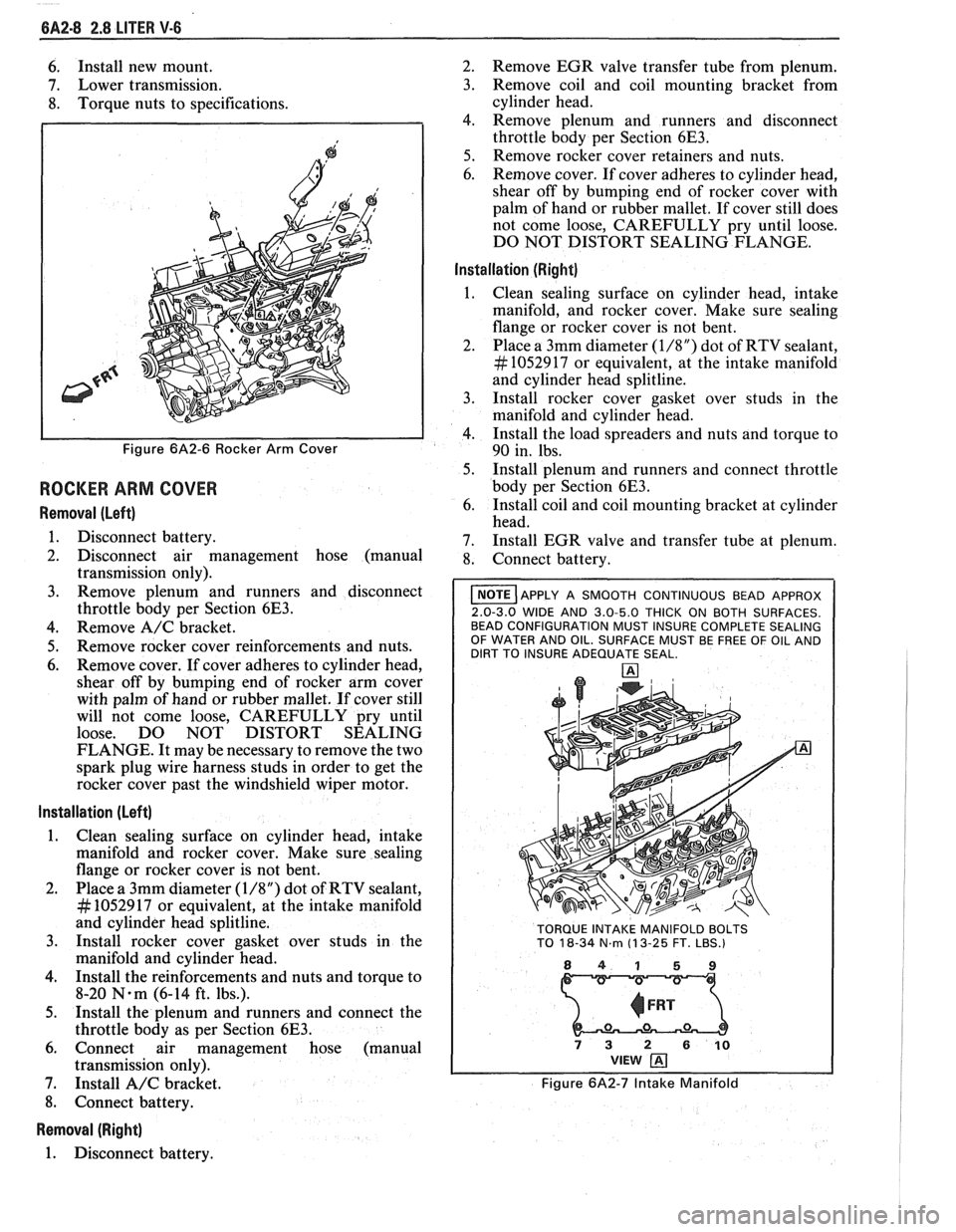
Figure 6A2-6 Rocker Arm Cover
ROCKER ARM COVER
Removal (Left)
1. Disconnect battery.
2. Disconnect air management hose (manual
transmission only).
3. Remove plenum and runners and disconnect
throttle body per Section
6E3.
4. Remove A/C bracket.
5. Remove rocker cover reinforcements and nuts.
6. Remove cover. If cover adheres to cylinder head,
shear off by bumping end of rocker arm cover
with palm of hand or rubber mallet. If cover still
will not come loose, CAREFULLY pry until
loose. DO NOT DISTORT SEALING
FLANGE. It may be necessary to remove the two
spark plug wire harness studs in order to get the
rocker cover past the windshield wiper motor.
Installation (Left)
1. Clean sealing surface on cylinder head, intake
manifold and rocker cover. Make sure sealing
flange or rocker cover is not bent.
2. Place a 3mm diameter
(1/8") dot of RTV sealant,
# 1052917 or equivalent, at the intake manifold
and cylinder head splitline.
3. Install rocker cover gasket over studs in the
manifold and cylinder head.
4. Install the reinforcements and nuts and torque to
8-20
N.m (6-14 ft. lbs.).
5. Install the plenum and runners and connect the
throttle body as per Section
6E3.
6. Connect air management hose (manual
transmission only).
7. Install
A/C bracket.
8. Connect battery.
Removal (Right)
1. Disconnect battery. 2.
Remove EGR valve transfer tube from plenum.
3. Remove coil and coil mounting bracket from
cylinder head.
4. Remove plenum and runners and disconnect
throttle body per Section
6E3.
5. Remove rocker cover retainers and nuts.
6. Remove cover. If cover adheres to cylinder head,
shear off by bumping end of rocker cover with
palm of hand or rubber mallet. If cover still does
not come loose, CAREFULLY pry until loose.
DO NOT DISTORT SEALING FLANGE.
Installation (Right)
Clean sealing surface on cylinder head, intake
manifold, and rocker cover. Make sure sealing
flange or rocker cover is not bent.
Place a 3mm diameter
(1/8") dot of RTV sealant,
# 1052917 or equivalent, at the intake manifold
and cylinder head splitline.
Install rocker cover gasket over studs in the
manifold and cylinder head.
Install the load spreaders and nuts and torque to
90 in. lbs.
Install plenum and runners and connect throttle
body per Section
6E3.
Install coil and coil mounting bracket at cylinder
head.
Install EGR valve and transfer tube at plenum.
Connect battery.
I NOTE ]APPLY A SMOOTH CONTINUOUS BEAD APPROX
2.0-3.0 WIDE AND 3.0-5.0 THICK ON BOTH SURFACES.
BEAD CONFIGURATION MUST INSURE COMPLETE SEALING
OF WATER AND OIL. SURFACE MUST BE FREE OF OIL AND
DIRT TO INSURE ADEQUATE SEAL.
TORQUE INTAKE MANIFOLD BOLTS
TO
18-34 N.m (1 3-25 FT. LBS.)
841 59
73 2 610 VIEW
Figure 6A2-7 Intake Manifold
Page 360 of 1825
2.8 LITER V-6 6A2-9
INTAKE MANIFOLD (FIGURE 6A2-7)
Removal
Disconnect battery.
Remove air cleaner.
Drain coolant.
Refer to Section 6E3 for removal of the following
PFI sub-assemblies.
e Plenum
e Fuel Rail
e Runner
Disconnect spark plug wires at spark plugs.
Disconnect wires at coil.
Remove distributor cap and spark plug wires.
Mark distributor position and remove hold down
bracket.
Remove distributor.
Remove air management hose, manual
transmission only.
Disconnect emission canister hoses. Remove pipe
bracket (front left valve cover).
Remove left valve cover.
Remove air management bracket, manual
transmission only.
Remove right valve cover.
Remove upper radiator hose.
Disconnect heater hose.
Disconnect coolant switches.
Remove manifold bolts.
Remove manifold. Discard manifold gaskets and
remove loose RTV from front and rear ridges of
cylinder case.
Installation
When installing intake gaskets, notice that the
gaskets are marked Right Side and Left Side
(carbureted only). Use them only as indicated to
maintain designed efficiency of this engine.
1. Make
sure that no oil or water is present on
surface when new RTV is applied. Place a 5mm
diameter
(3/16") bead of RTV, # 1052917 or
equivalent, on each ridge.
2. Install
new intake gaskets on cylinder heads.
Hold in place by extending ridge RTV bead up
6mm onto the gasket ends. The new intake
gaskets will have to be cut, where indicated, to
install behind push rods. Cut only those areas
that are necessary.
3. Install intake
manifold on engine. Make sure
areas between case ridges and intake are
completely sealed.
4. Install manifold retaining bolts and nuts and
torque in the sequence shown in Figure 6A2-7.
5. Install heater and radiator hose to manifold.
6. Install rocker covers as previously outlined.
7. Connect coolant switches.
8. Install air management bracket.
9. Install pipe bracket (front left rocker cover).
10. Install distributor, distributor cap and retaining
nut. Do not tighten.
11. Refer to Section 6E3 for installation of PFI
sub-assemblies removed. 12.
Connect
necessary wires and hoses.
13. Fill cooling system with
the proper mixture of
ethylene glycol anti-freeze and water. Do not
install radiator cap.
14. Start
engine, set intitial timing. After set, torque
distibutor hold down clamp bolt to 34
N-m (25
lb. ft.). Recheck timing after torquing bolt.
15. Let engine
run until radiator upper hose becomes
hot (thermostat open).
16. With
engine idling, add coolant to radiator, if
necessary, until level reaches bottom of filler
neck.
17. Install
radiator cap, making sure arrows on cap
line up with overflow tube.
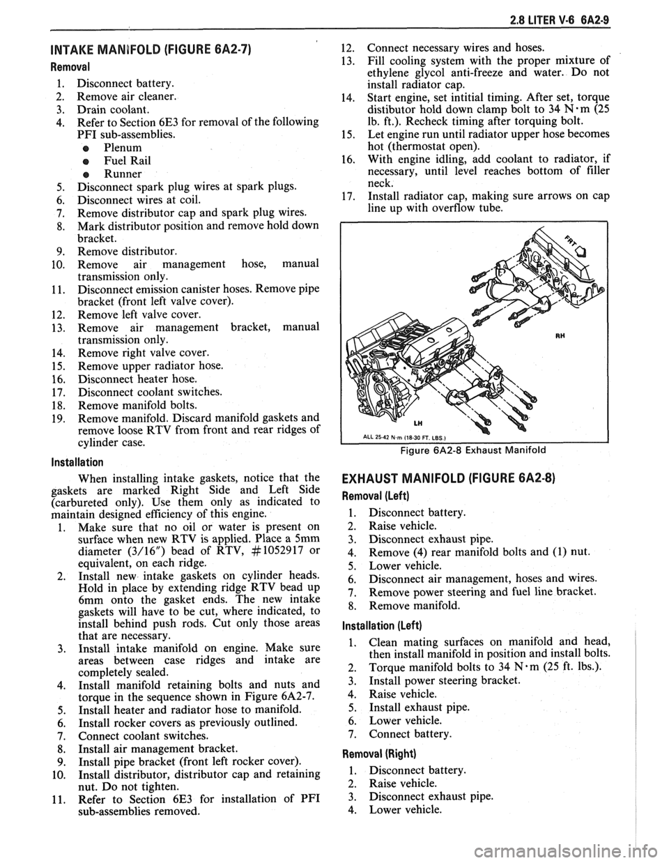
Figure 6A2-8 Exhaust Manifold
EXHAUST MANIFOLD (FIGURE 6A2-8)
Removal (Left)
1. Disconnect battery.
2. Raise vehicle.
3. Disconnect exhaust pipe.
4. Remove
(4) rear manifold bolts and (1) nut.
5. Lower vehicle.
6. Disconnect air management, hoses and wires.
7. Remove power steering and fuel line bracket.
8. Remove manifold.
Installation (Left)
1. Clean mating surfaces on manifold and head,
then install manifold in position and install bolts.
2. Torque
manifold bolts to 34
N.m (25 ft. lbs.).
3. Install power steering bracket.
4. Raise vehicle.
5. Install exhaust pipe.
6. Lower vehicle.
7. Connect battery.
Removal (Right)
1. Disconnect battery.
2. Raise vehicle.
3. Disconnect exhaust pipe.
4. Lower vehicle.