PONTIAC FIERO 1988 Service Repair Manual
Manufacturer: PONTIAC, Model Year: 1988, Model line: FIERO, Model: PONTIAC FIERO 1988Pages: 1825, PDF Size: 99.44 MB
Page 511 of 1825
6EZ-A-20 5.0L (VIN E) DRIVEABILITY AND EMISSIONS
FUEL PRESSURE
CHART A-7
(Page 2 of 2)
FUEL SYSTEM DIAGNOSIS
5.OL (VIN E) "F" SERIES (TBI)
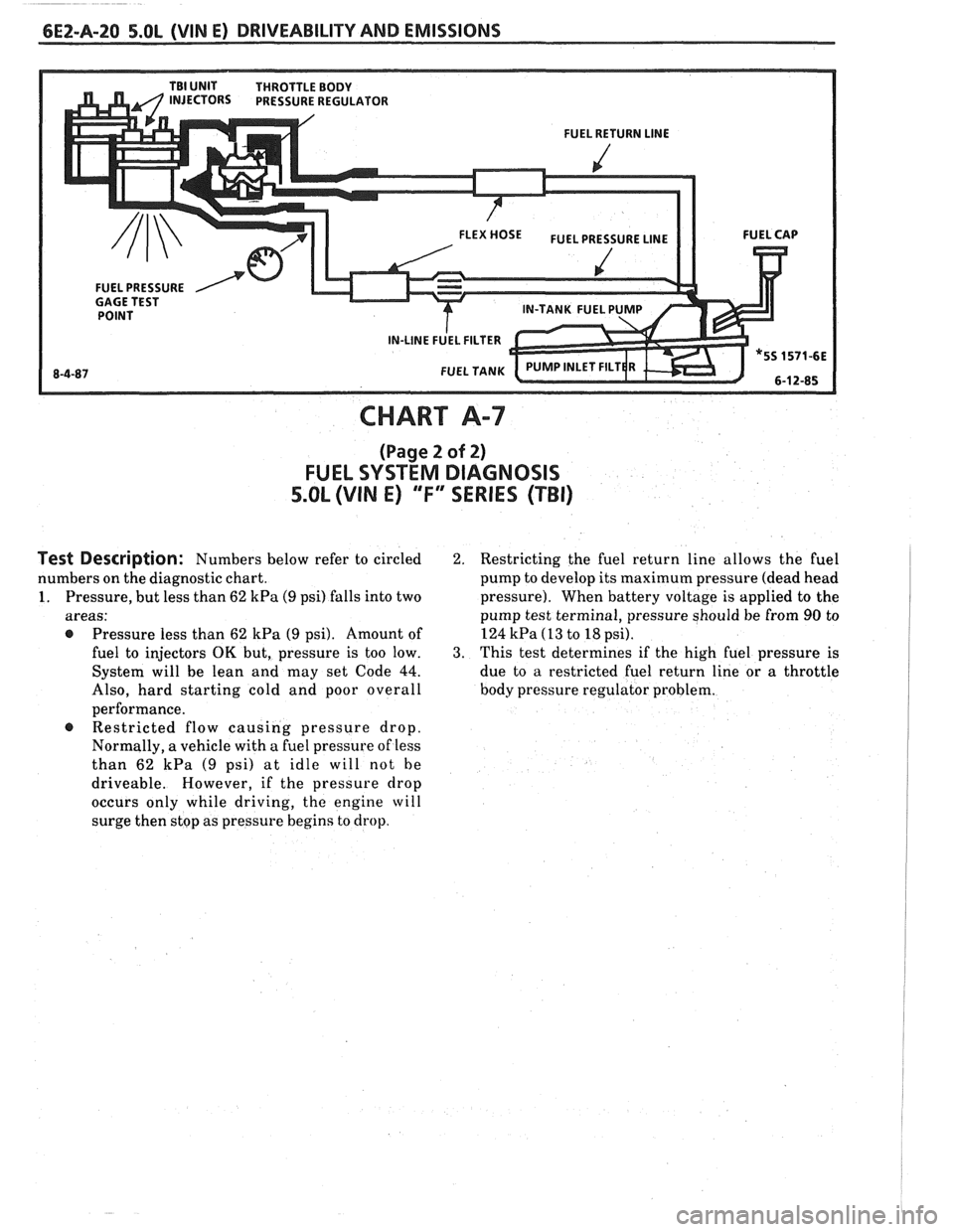
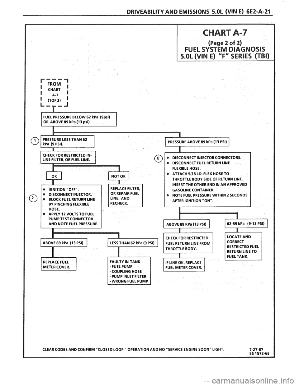
Test Description: Numbers below refer to circled
numbers on the diagnostic chart.
1. Pressure, but less than 62 kPa (9 psi) falls into two
areas:
@ Pressure less than 62 kPa (9 psi). Amount of
fuel to injectors
OK but, pressure is too low.
System will be lean and may set Code
44.
Also, hard starting cold and poor overall
performance. Restricted flow causing pressure drop.
Normally, a vehicle with a fuel pressure of less
than 62
kPa (9 psi) at idle will not he
driveable. However, if the pressure drop
occurs only while driving,
the engine will
surge then stop as pressure begins to drop.
2. Restricting the fuel return line allows the fuel
pump to develop its maximum pressure (dead head
pressure). When battery voltage is applied to the
pump test terminal, pressure should be from
90 to
124
kPa (13 to 18 psi).
3. This test determines if the high fuel pressure is
due to a restricted fuel return line or a throttle
body pressure regulator problem.
Page 512 of 1825
DRIVEABILITY AND EMISSIONS 5.OL (VIN E) CEZ-A-21
@ DISCONNECT FUEL RETURN LlNE
FLEXIBLE HOSE.
ATTACH
5/16 1.D. FLEX HOSE TO
THROTTLE BODY SIDE OF RETURN LINE.
INSERT THE OTHER END IN AN APPROVED
GASOLINE CONTAINER.
r NOTE FUEL PRESSURE WITHIN 2 SECONDS
@ APPLY 12 VOLTS TO FUEL
CHECK FOR RESTRICTED
FUEL RETURN
LlNE FROM
THROTTLE BODY.
CLEAR CODES AND CONFIRM "CLOSED LOOP
" OPERATION AND NO "SERVICE ENGINE SOON" LIGHT.
Page 513 of 1825
OXYGEN ( 0,) SENSOR GROUND
-
CODE 13
OXYGEN SENSOR CIRCUIT
(OPEN CIRCUIT)
5.OL (VIN E) ""FYERIES (TBI)
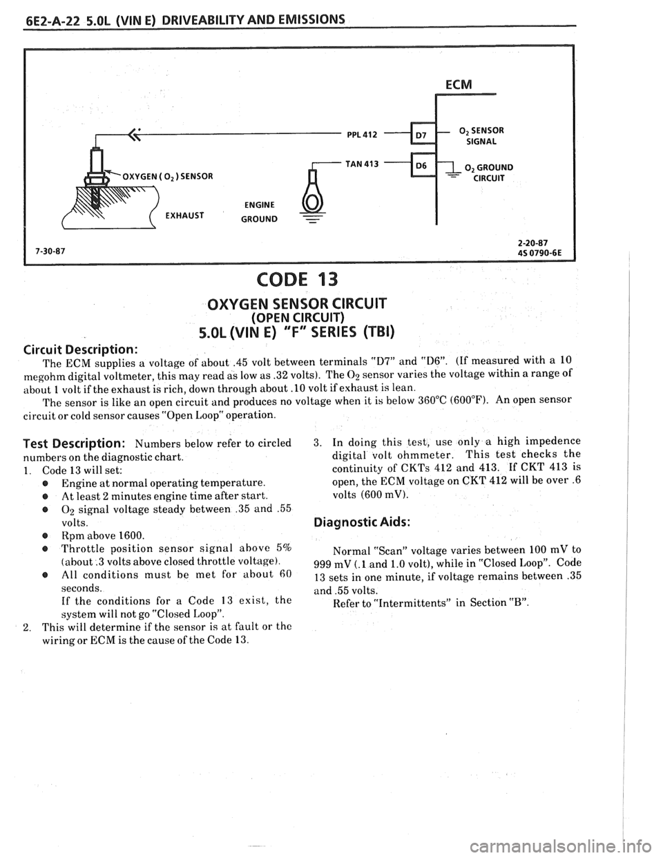
Circuit Description:
The ECM supplies a voltage of about .45 volt between terminals "D7" and "D6". (If measured with a 10
megohm digital voltmeter, this may read as low as .32 volts). The 02 sensor varies the voltage within a range of
about
1 volt if the exhaust is rich, down through about .10 volt if exhaust is lean.
The sensor is like an open circuit and produces no voltage when it is below 360°C (600°F). An open sensor
circuit or cold sensor causes "Open Loop" operation.
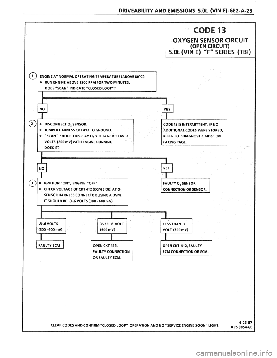
Test Description: Numbers below refer to circled 3. In doing this test, use only a high impedence
numbers on the diagnostic chart. digital
volt ohmmeter. This test
checks the
1. Code 13 will set: continuity of CKTs 412 and 413. If CKT 413 is
@ Engine at normal operating temperature. open,
the ECM voltage on CKT 412 will be over .6
@ At least 2 minutes engine time after start. volts (600 mV).
@ On signal
voltage steady between .35 and .55
volts. Diagnostic Aids:
@ Rpm above 1600.
@ Throttle position sensor signal above 5%
Normal "Scan" voltage varies between 100 mV to
(about .3 volts above closed throttle voltage). 999 mV (. 1 and 1.0 volt), while in "Closed Loop". Code @ must be met for about 13 sets in one minute, if voltage remains between .35
seconds. and .55 volts.
If the conditions for a Code
13 exist, the
Refer to "Intermittents" in Section "B". system will not go "Closed Loop".
2. This will determine if the sensor is at fault or the
wiring or ECM is the cause of the Code
13.
Page 514 of 1825
DRIVEABILITY AND EMISSIONS 5.OL (VIN E) 6EZ-A-23
"SCAN" SHOULD DISPLAY 0, VOLTAGE BELOW -2
VOLTS (200 mV) WITH ENGINE RUNNING.
CHECK VOLTAGE OF CKT 412 (ECM SIDE) AT
O2
Page 515 of 1825
bE2-A-24 S.OL (VIN E) DRIVEABILITY AND EMlSSlONS
SENSOR GND
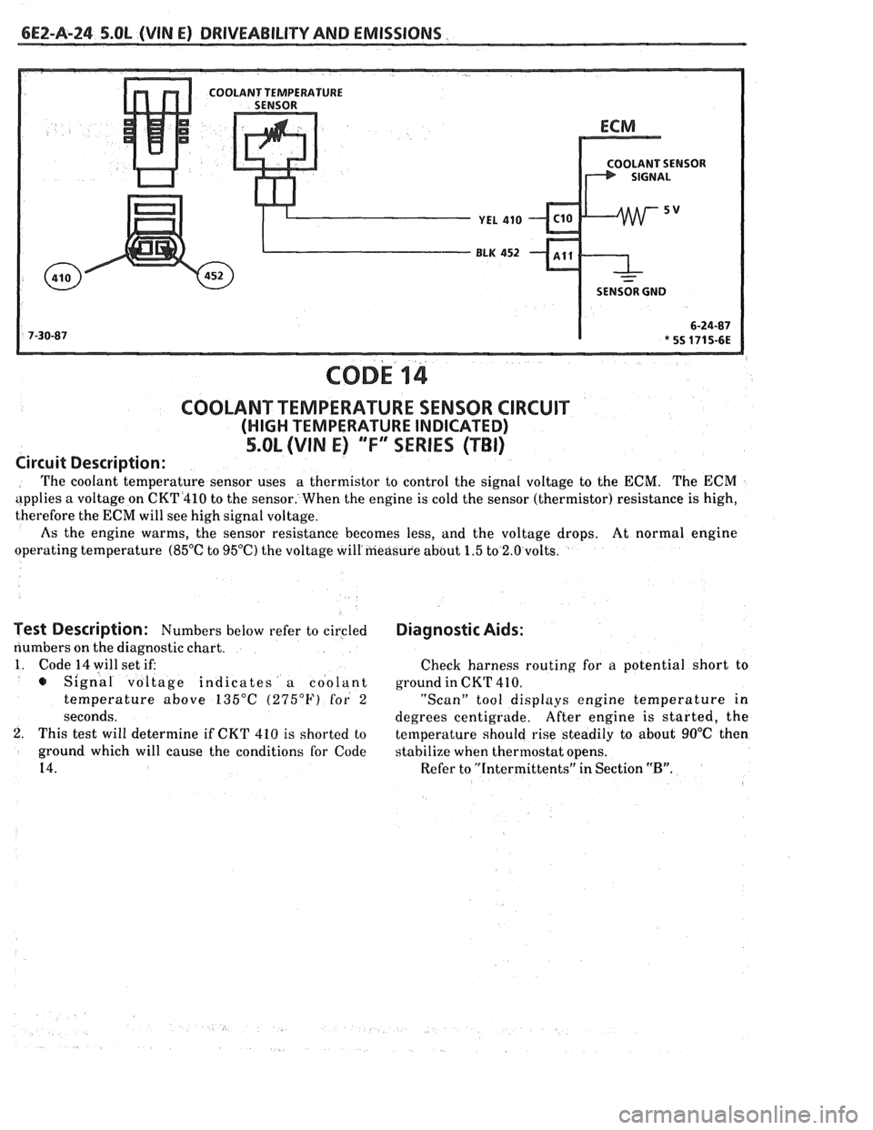
COD^ 14
COOLANT TEMPERATURE SENSOR CIRCUIT
(HIGH TEMPERATURE INDICATED)
5.OL (VIN E) "F"" SERIES (TBI)
Circuit Description:
The coolant temperature sensor uses a
thermistor to control the signal voltage to the ECM. The ECM
applies a voltage on CKT4410 to the sensor. When the engine is cold the sensor (thermistor) resistance is high,
therefore the
ECM will see high signal voltage.
As the engine warms, the sensor resistance becomes less, and the voltage drops. At normal engine
operating temperature
(85°C to 95OC) the voltage will'measure about 1.5 to 2.0 volts.
Test Description: Numbers below refer to circled
numbers on the diagnostic chart.
1. Code 14 will set if:
s Signal voltage indicates a coolant
temperature above
135°C (275°F) for 2
seconds.
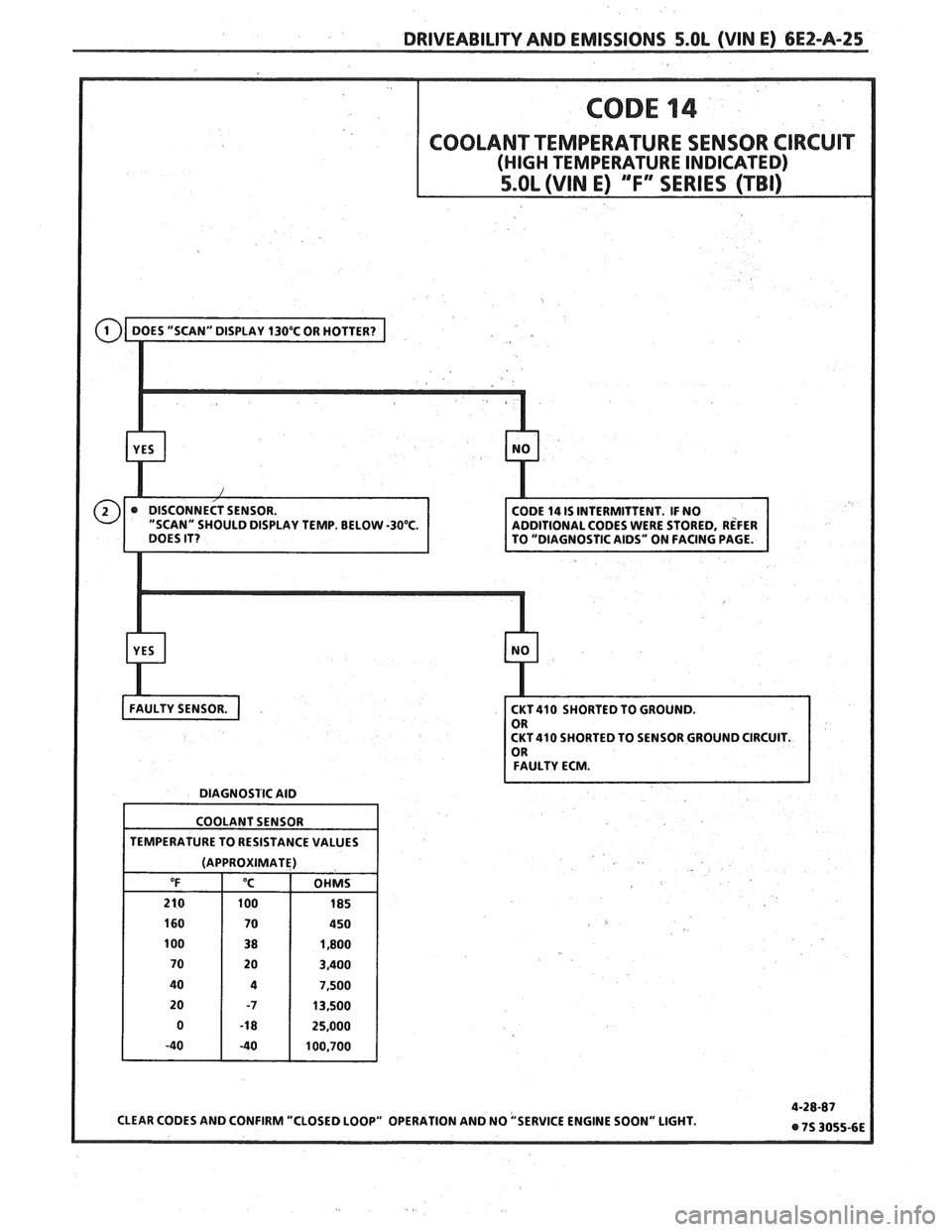
2. This test will determine if CKT 410 is shorted to
ground which will cause the conditions for Code
14.
Diagnostic Aids:
Check harness routing for a potential short to
ground in CKT
41 0.
"Scan" tool displays engine temperature in
degrees centigrade. After
engine is started, the
temperature should rise steadily to about
90°C then
stabilize when thermostat opens.
Refer to "Intermittents" in Section
"B".
Page 516 of 1825
DRIVEABILITY AND EMISSIONS 5.OL (VIN E) 6E2-A-25
LAY TEMP. BELOW -30°C.
CKT 410 SHORTED TO SENSOR GROUND CIRCUIT.
FAULTY ECM.
DIAGNOSTIC AID
COOLANT SENSOR
TEMPERATURE TO RESISTANCE VALUES
(APPROXIMATE)
Page 517 of 1825
6EZ-A-26 5.8L (VIN E) DRIVEABILITY AND EMISSIONS
OLANT SENSOR
SENSOR GND
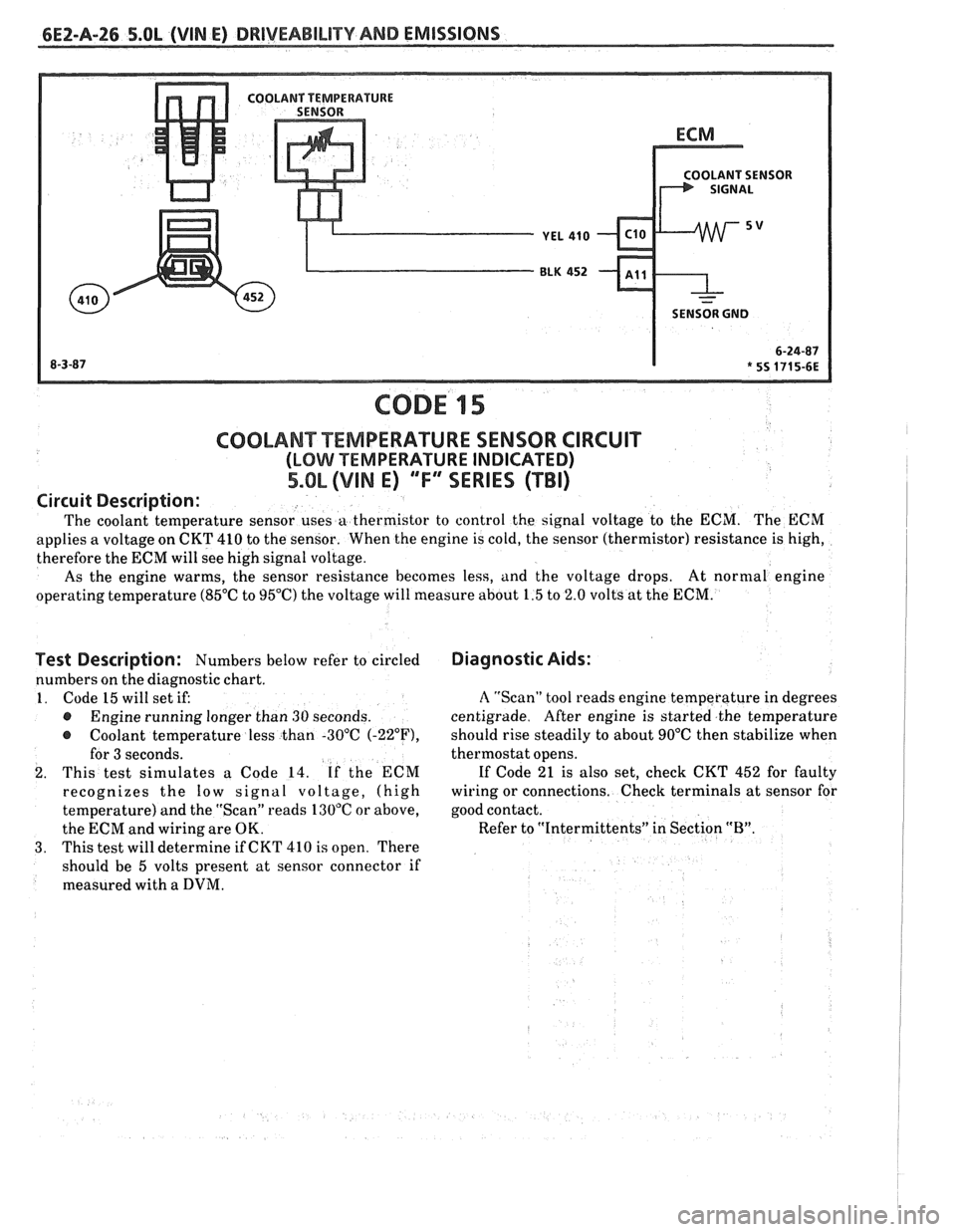
CODE 15
Test Description: Numbers below refer to circled
numbers on the diagnostic chart.
1. Code 15 will set if:
@ Engine running longer than 30 seconds.
@ Coolant temperature less than -30°C (-22"F),
for 3 seconds.
2. This test simulates a Code 14. If the ECM
recognizes the
low signal voltage, (high
temperature) and the "Scan" reads 130°C or above,
the ECM and wiring are OK.
3. This test will determine if CKT 410 is open. There
should be 5 volts present at sensor connector if
measured with a
DVM.
COOLANT TEMPERATURE SENSOR CIRCUIT
(LOMI TEMPERATURE INDICATED)
5.OL (VIM E) ""FYERIES (TBI)
Diagnostic Aids:
Circuit
Description:
The coolant temperature sensor uses a thermistor to control the signal voltage to the ECM. The ECM
applies a voltage on CKT 410 to the sensor. When the engine is cold, the sensor (thermistor) resistance is high,
therefore the ECM will see high signal voltage.
As the engine warms, the sensor resistance becomes less, and the voltage drops. At
normal engine
operating temperature (85°C to 95°C) the voltage will measure about 1.5 to 2.0 volts at the ECM.
A "Scan" tool reads engine temperature in degrees
centigrade. After engine is started the temperature
should rise steadily to about 90°C then stabilize when
thermostat opens.
If Code 21 is also set, check CKT 452 for faulty
wiring or connections. Check terminals at sensor for
good contact.
Refer to "Intermittents" in Section
"B".
~
Page 518 of 1825
DRIVEABILITY AND EMISSIONS S.OL (VIN E) 6E2-A-27
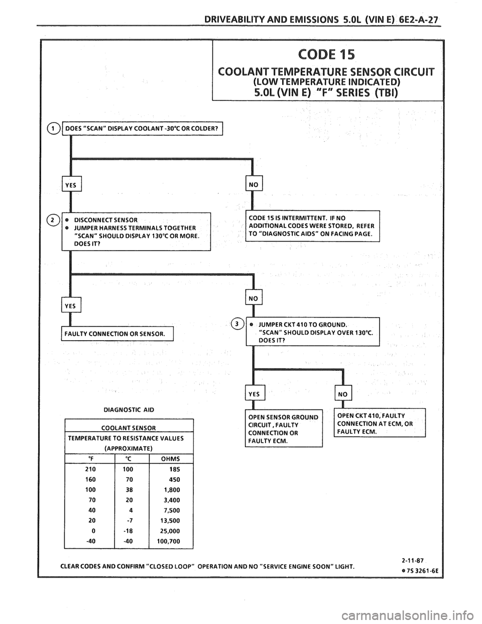
" SHOULD DISPLAY 130°C OR MORE.
DIAGNOSTIC AID
CLEAR CODES AND CONFIRM "CLOSED LOOP" OPERATION AND NO "SERVICE ENGINE SOON" LIGHT.
COOLANT
SENSOR
TEMPERATURE TO RESISTANCE VALUES
(APPROXIMATE)
"F "C OHMS
210 100 185
160 70 450
100 38 1,800
70 20 3,400
40
4 7,500
20 -7 13,500
0
-1 8 25,000
-40 -40 100,700
Page 519 of 1825
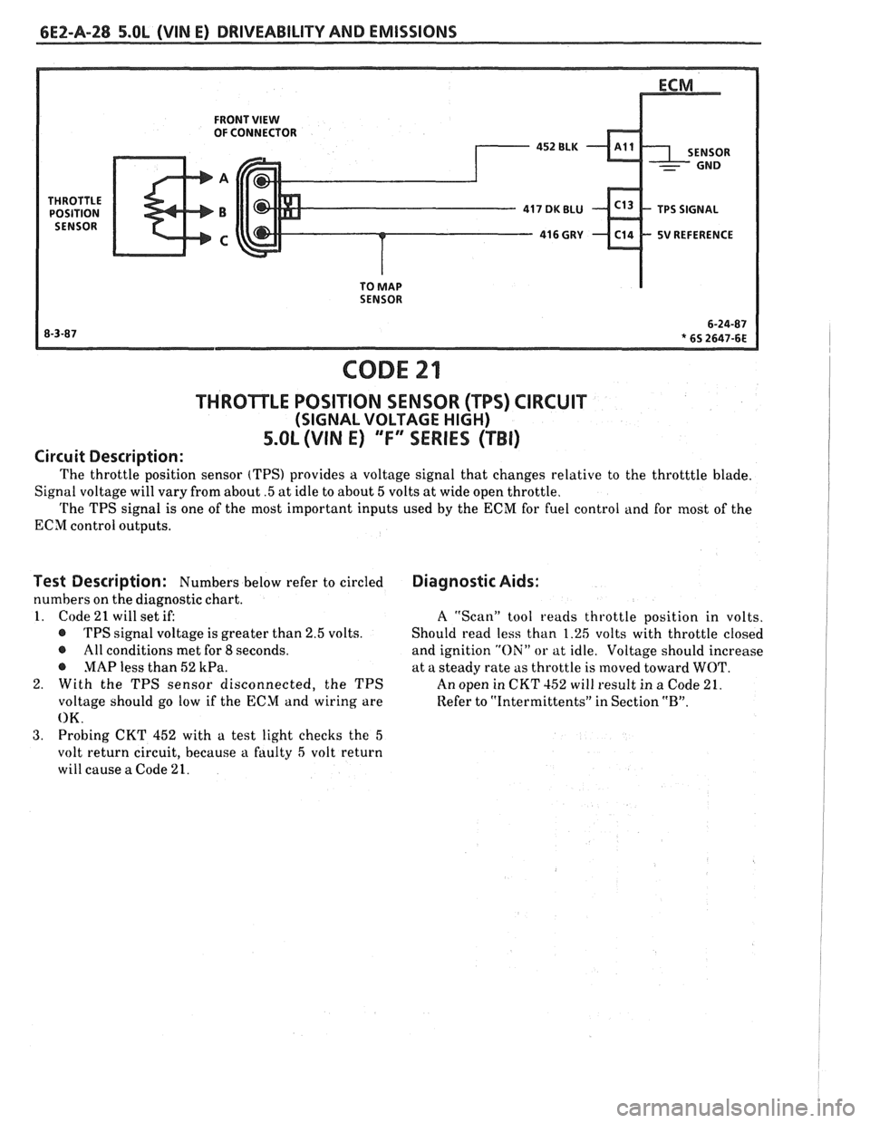
6EZ-A-28 5.OL (VIN E) DRIVEABILITY AND EMISSIONS
FRONT VIEW OF CONNECTOR
5V REFERENCE
TO
MAP SENSOR
CODE 21
THROTLE POSITION SENSOR (TPS) CIRCUIT
(SIGNAL VOLTAGE HIGH)
5.OL (VIN E) "F" "SERIES ("FBI)
Circuit Description:
The throttle position sensor (TPS) provides a voltage signal that changes relative to the throtttle blade.
Signal voltage will vary from about
.5 at idle to about 5 volts at wide open throttle.
The TPS signal is one of the most important inputs used by the ECM for fuel control and for most of the
ECM control outputs.
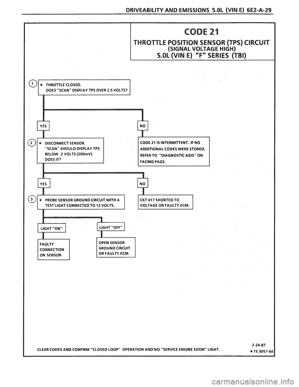
Test Description: Numbers below refer to circled
numbers on the diagnostic chart.
1. Code
21 will set if:
@ TPS signal voltage is greater than 2.5 volts.
@ All conditions met for 8 seconds.
@ MAP less than 52 kPa.
2. With the TPS sensor disconnected, the TPS
voltage should go low if the ECM and wiring are
OK.
3. Probing CKT 452 with a test light checks the 5
volt return circuit, because a faulty 5 volt return
will cause
a Code 21.
Diagnostic Aids:
A ''Scan" tool reads throttle position in volts.
Should read less than 1.26 volts with throttle closed
and ignition
"Oili" or at idle. Voltage should increase
at a steady rate as throttle is moved toward
WOT.
An open in CKT 152 will result in a Code 21.
Refer to
"Intermittents" in Section "B".
Page 520 of 1825
DRIVEABILITY AND EMISSIONS 5.OL (WIN E) 6E2-A-29
BELOW .2 VOLTS (2OOrnV). REFER TO "DIAGNOSTIC AIDS" ON
FACING PAGE.