PONTIAC FIERO 1988 Service Manual PDF
Manufacturer: PONTIAC, Model Year: 1988, Model line: FIERO, Model: PONTIAC FIERO 1988Pages: 1825, PDF Size: 99.44 MB
Page 61 of 1825
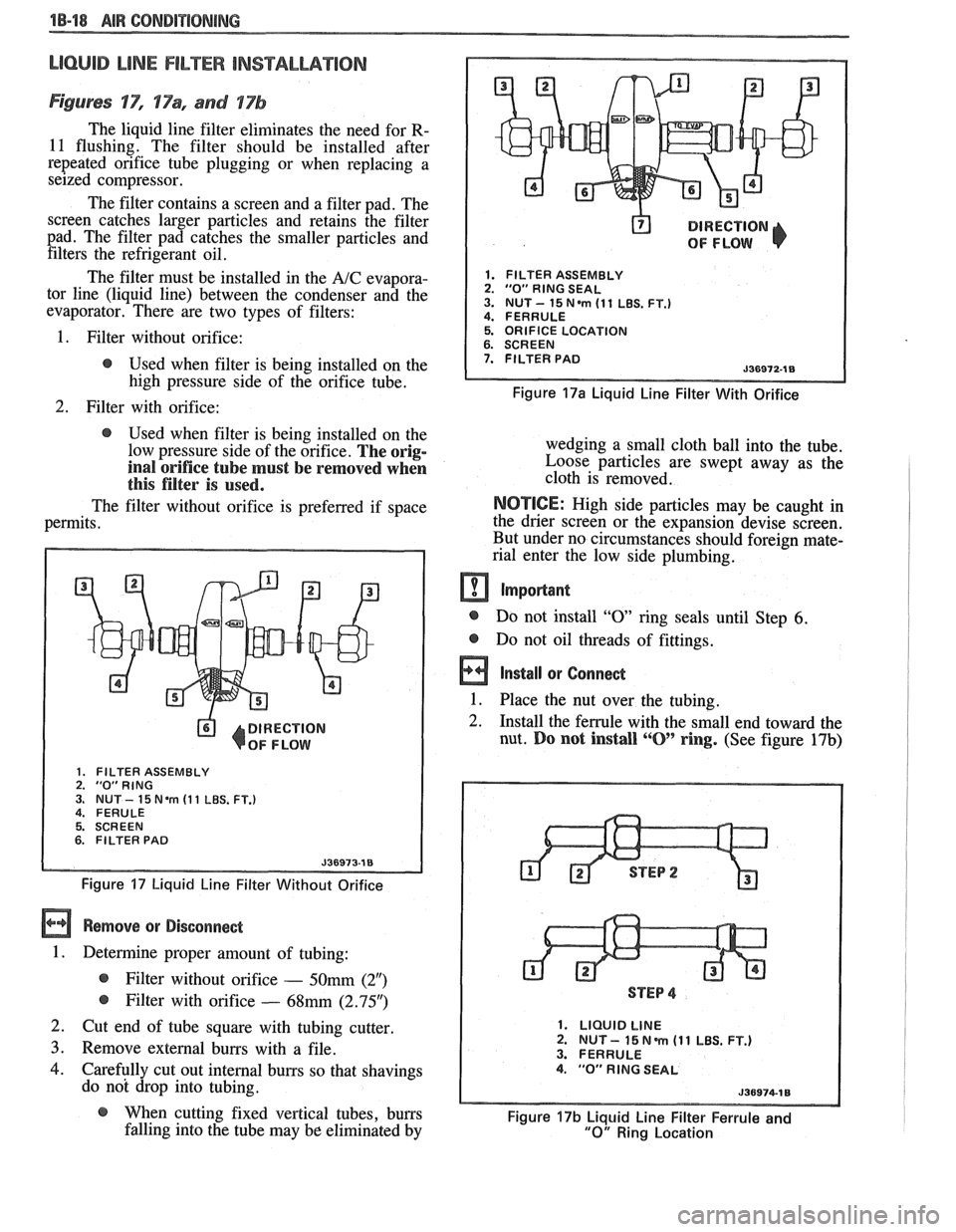
LlOQllD LiNE FILTER INSTALLATION
Figures 'IT", 17% and 17b
The liquid line filter eliminates the need for R-
11 flushing. The filter should be installed after
repeated orifice tube plugging or when replacing a
seized compressor.
The filter contains a screen and a filter pad. The
screen catches larger particles and retains the filter
pad. The filter pad catches the smaller particles and filters the refrigerant oil.
The filter must be installed in the
A/C evapora-
tor line (liquid line) between the condenser and the
evaporator. There are two types of filters:
@ DIRECTION
OF FLOW
1. FILTER ASSEMBLY 2. "0" RlNG SEAL 3. NUT- 15N.m (11 LBS. FT.) 4. FERRULE
1. Filter without orifice: 5. ORIFICE LOCATION
@ Used when filter is being installed on the 7. FILTER PAD
high pressure side of the orifice tube. Figure 17a Liquid Line Filter With Orifice
2. Filter with orifice:
@ Used when filter is being installed on the
low pressure side of the orifice.
The orig-
inal orifice tube must be removed when
this filter is used.
The filter without orifice is preferred if space
permits.
DIRECTION
OF FLOW
1. FILTER ASSEMBLY 2. "0"RING 3. NUT - 15 Nem (1 1 LBS. FT.) 4. FERULE
5. SCREEN
6. FILTER PAD
Figure 17 Liquid Line Filter Without Orifice
Remove or Disconnect
1. Determine proper amount of tubing:
@ Filter without orifice - 50mm (2")
@ Filter with orifice - 68mm (2.95")
2. Cut end of tube square with tubing cutter
3. Remove external burrs with a file.
4. Carefully cut out internal burrs so that shavings
do not drop into tubing. wedging a small cloth ball
into the tube.
Loose particles are swept away as the
cloth is removed.
NOTICE: High side particles may be caught in
the drier screen or the expansion devise screen.
But under no circumstances should foreign mate-
rial enter the low side plumbing.
m Important
@ Do not install "0 ring seals until Step 6.
@ Do not oil threads of fittings.
a Install or Connect
1. Place the nut over the tubing. -
2. Install the ferrule with the small end toward the
nut.
Do not install ""0' ring. (See figure 17b)
STEP 4
1. LIQUID LINE 2. NUT - 15 N m (1 1 LBS. FT.) 3. FERRULE 4. "0" RlNG SEAL
@ When cutting fixed vertical tubes, burrs Figure 17b Liquid Line Filter Ferrule and falling into the tube may be eliminated by "0" Ring Location
Page 62 of 1825
AIR CONDITIONING 18-19
3. Push the tube into the fitting, bottoming it out.
Tighten
@ Torque nut to 15 Nam (11 lbs. ft.).
4. Dissasemble the joint.
5. Lubricate the
"0" ring with clean 525 viscosity
refrigerant oil.
6. Install the
"0" ring
on the tube. (See figure 17b)
7. Reassemble joint.
Tighten
@ Torque nut to 15 Nem (11 lbs. ft.).
8. Evacuate, charge, and leak test the system.
EXPANSlON "%BE (ORIFICE) SERVlCE
Remove or Disconnect
1. Discharge system.
2. Loosen fitting
at liquid line to evaporator inlet
pipe and remove tube carefully with needle
nosed pliers or Tool
5-26549-C or equivalent.
Install or Connect
1. Install
new orifice tube with shorter screen end
in first.
2. Install
liquid line and torque to proper
specification.
3. Evacuate and charge system.
In the event that difficulty is encountered during
the removal of a restricted or plugged expansion tube
(orifice tube), the following procedure is recom-
mended:
1. Remove
as much of any impacted residue as
possible.
2. Carefully apply heat with heat gun (hair drier,
epoxy drier or equivalent) approximately
114
inch from dimples on inlet pipe. Do not over-
heat pipe.
NOTICE: If the system has a pressure switch
near the orifice tube location, it should be
removed prior to heating the pipe to avoid dam-
age to switch.
3. While applying heat, use orifice removal tool
5-26549-C to grip the orifice tube. Use a turning
motion along with a push-pull motion to loosen
to the impacted orifice tube and remove it.
4. Swab inside of evaporator inlet pipe with R-11.
5, Add
1 oz. of 525 viscosity refrigerant oil to
system.
6. Lubricate new orifice tube and O-ring with 525'
viscosity refrigerant oil and insert into inlet
pipe. Install in proper direction (smaller screen
first).
ACCUMULATOR ASSEMBLY SERVICE
The accumulator assembly for the refrigerant
system has a service replacement which includes two
(2) O-rings (for the inlet and outlet connections). The
desiccant within the shell is NOT serviced separately
- it is part of the sealed accumulator assembly. See
REFRIGERANT OIL DISTRIBUTION for condi-
tions when the accumulator must be removed from the
vehicle to measure the amount of oil present inside the
accumulator.
The accumulator assembly should ONLY be
replaced when:
1. A physical perforation to the accumulator is
found, resulting in a leak.
2. If the system is open to air for an extended
period of time (due to a front-end collision,
removed parts, ect.). The desiccant bag will be
saturated with moisture.
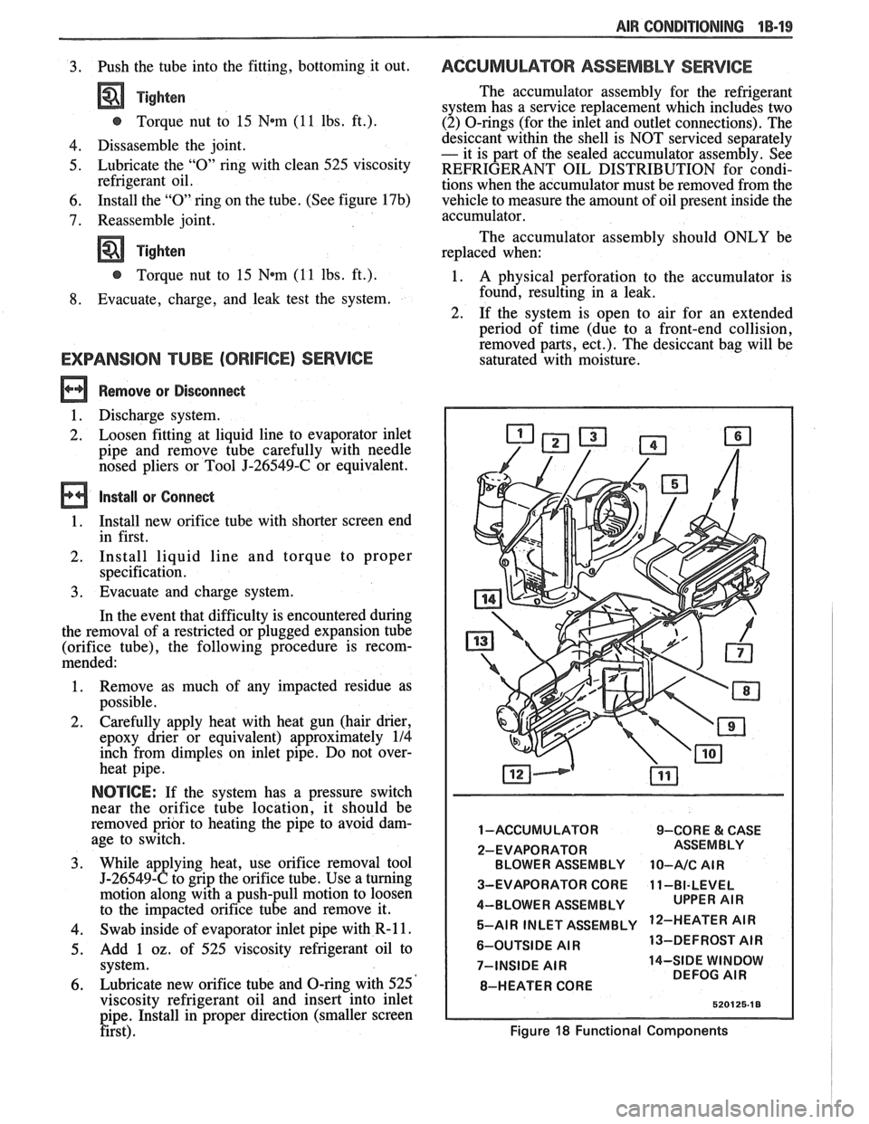
1 -ACCUMULATOR 9-CORE & CASE
2-EVAPORATOR BLOWER ASSEMBLY
10-A/C AIR
3-EVAPORATOR CORE 11-BI-LEVEL
4-BLOWER ASSEMBLY 5-AIR INLET ASSEMBLY
'IR
6-OUTSIDE AIR 13-DEFROST
AIR
7-INSIDE
AIR 14-SIDE WINDOW
DEFOG AIR
8-HEATER CORE
Figure 18 Functional Components
Page 63 of 1825
18-28 AIR CONDITIONING
DO NOT REPLACE the accumulator assembly
when:
1. Merely a dent is found in the outer shell of the
accumulator.
2. A
vehicle is involved in a collision and no phys-
ical perforation to the accumulator is found.
OM-VEHICLE SERVICE
R-"1 CHARGING CAPACITIES
The 420ml (14 fl. oz.) disposable can of R-12
refrigerant is equivalent to .399 kg (. 88 lb.).
BLOWER MOTOR
a Remove or Disconnect
1. Disconnect negative battery cable.
2. Remove motor cooling tube.
3. Disconnect electrical connections.
4. Remove blower motor attaching screws, remove
motor and case assembly.
5. Loosen retaining nut and remove blower cage
from motor shaft.
6. Inspect blower cage for broken vanes, etc.
Replace if necessary.
Install or Connect
1. Reverse removal procedure to reinstall. Replace
seals or sealant as required.
HI-BLOWER RELAY
Relay is a plug-in type with connector mounted
on top of the evaporator case.
BLOWER RESISTOR
Remove or Disconnect
1. Disconnect negative battery cable.
2. Disconnect electrical connections.
3. Remove two (2) screws, remove resistor.
Install or Connect
1. Reverse removal procedure to reinstall.
CONTROLLER, BLOWER SWITCH OR
WCUUM VALVE
Remove or Disconnect
1. Disconnect negative battery cable.
2. Remove NC control-radio console trim plate.
3. Remove three (3) NC control retaining screws.
4. Pull A/C control out and disconnect electrical
and vacuum connections and remove tempera-
ture cable.
5. Remove A/C control and replace vacuum valve
or blower switch as required.
Install or Connect
1. Reverse removal procedure to reinstall. Install
lower right screw in controller first to align con-
troller in console.
TEMPERATURE CONTROL CABLE,
VACUUM HARNESS
Remove or Disconnect
1. Remove the following hush panel(s):
a. Vacuum Harness - R.H. and L.H. hush
panel.
b. Temperature Cable
- R.H. hush panels.
Remove
controller/radio console trim plate.
Remove three (3) controller screws and pull
controller partially out of console.
Disconnect controller
end(s) of temperature
cable
andlor vacuum harness.
Disconnect component
end(s) of temperature
cable
andlor vacuum harness.
Install or Conned
1. Reverse removal procedure to reinstall. When
installing controller, install lower right screw
first to align controller location. Replace any
retaining straps, etc. removed.
2. Perform functional check of controller.
CONTROL WlRlNG HARNESS
a Remove or Disconnect
1. Disconnect negative battery cable.
2. Remove
control/radio console trim plate and
hush panels (see Section
8C).
3. Remove three (3) screws holding control in con-
sole and pull control out far enough to discon-
nect electrical and vacuum connector. Remove
controller.
4. Remove instrument panel carrier (see Section
8C).
5. Remove heater case covers (core and mode door
sides).
6. Remove two (2) interior screws and one (1)
exterior nut holding case to cowl. Pull left side
of case back to gain access to harness at cowl.
Case will still be retained by one (I) screw
behind the evaporator core
- do not attempt
complete removal of case. -
7. Loosen cowl grommet and disconnect purple
vacuum line.
Page 64 of 1825
AIR CONDITIONING 18-21
8. Disconnect blower motor
and blower resistor
electrical connection.
9. Remove hi-blower relay connector from evapo-
rator case.
10. Carefully pull
cowl grommet from cowl and pull
wiring
hmess into engine compartment.
Install or Connect
1. Reverse removal procedure to
reinstall. When
reinstalling controller, install lower right screw
first to align controller.
ACNENTILATIONIDEFROSVER DUCTS
See section 8C for removal.
HEATER CORE
Remove or Disconnect
1. Negative battery cable.
2. Drain cooling system.
3. Remove heater inlet and outlet hoses
from
heater core.
4. Remove right lower hush panel (see Section
8C).
5. Remove right
lower I.P. trim panel (see Section
8C) .
6. Remove lower right I.P. carrier to cowl screw.
7. Remove ECM attaching screws and move to the
side.
8. Remove four
(4) heater case cover screws.
Upper left screw may be reached with a long
318 ' socket extension through the I.P. openings
exposed by removal of the lower right I.P. trim
panel. Carefully lift the lower right corner of the
I.P. to align socket extension.
9. Remove heater case cover.
10. Remove core support plate
and baffle screws.
- -
11. Remove
heater core, support plate and baffle
from case.
Install or Conned
1. Reverse removal procedure to reinstall. Restore
all seals
and/or sealant disturbed during removal
procedure.
2. Refill cooling system and check for leaks.
LOWER (FLOOR) )-IEA"FEB$OU"fET
Remove or Disconnect
1. Console. (See Section 8C.)
2. L.H. and R.H. hush panels.
3. Two (2) floor outlet retaining screws.
4. Floor outlet from core case.
lnstall or Connect
1. Floor outlet to core case.
2. Two (2) floor outlet retaining screws.
3. L.H. and R.H. hush panels.
4. Console.
HEATER MODULE (CASE)
Remove or Disconnect
1. Disconnect negative battery cable.
2. Drain cooling system.
3. Remove hush panels and instrument panel car-
rier (see Section
8C).
4. Remove lower heater outlets.
5. Disconnect control cables and vacuum hoses at
module and controller.
6. Remove heater core.
7. Remove two (2) interior screws and one (I)
exterior nut holding case to cowl.
8. Remove evaporator core.
9. Remove screw holding case to cowl from engine
compartment side.
10. Remove case (module).
11. Transfer usable parts to new case (module).
lnstall or Conned
1. Reverse removal procedure to reinstall.
2. Refill coolant system.
3. Recharge
A/C system.
4. Inspect A/C and cooling system for leaks.
NC PRESSURE CYCLING SWITCH
Do not discharge A/C system. Pressure cycling
switch is mounted on
a Schrader-type valve.
Remove or Disconnect
1. Disconnect switch electrical connection.
2. Remove switch.
Install or Connect
1. Reverse removal procedure to reinstall. Tighten
switch to
4-5.5 N*m (35-49 in. lb.).
Ale CONTROL VACUUM TANK
Remove or Disconnect
1 . Disconnect vacuum hoses.
2. Remove vacuum
tank attaching screws, remove
tank.
lndall or Connect
1. Reverse removal procedure to
reinstall.
Page 65 of 1825
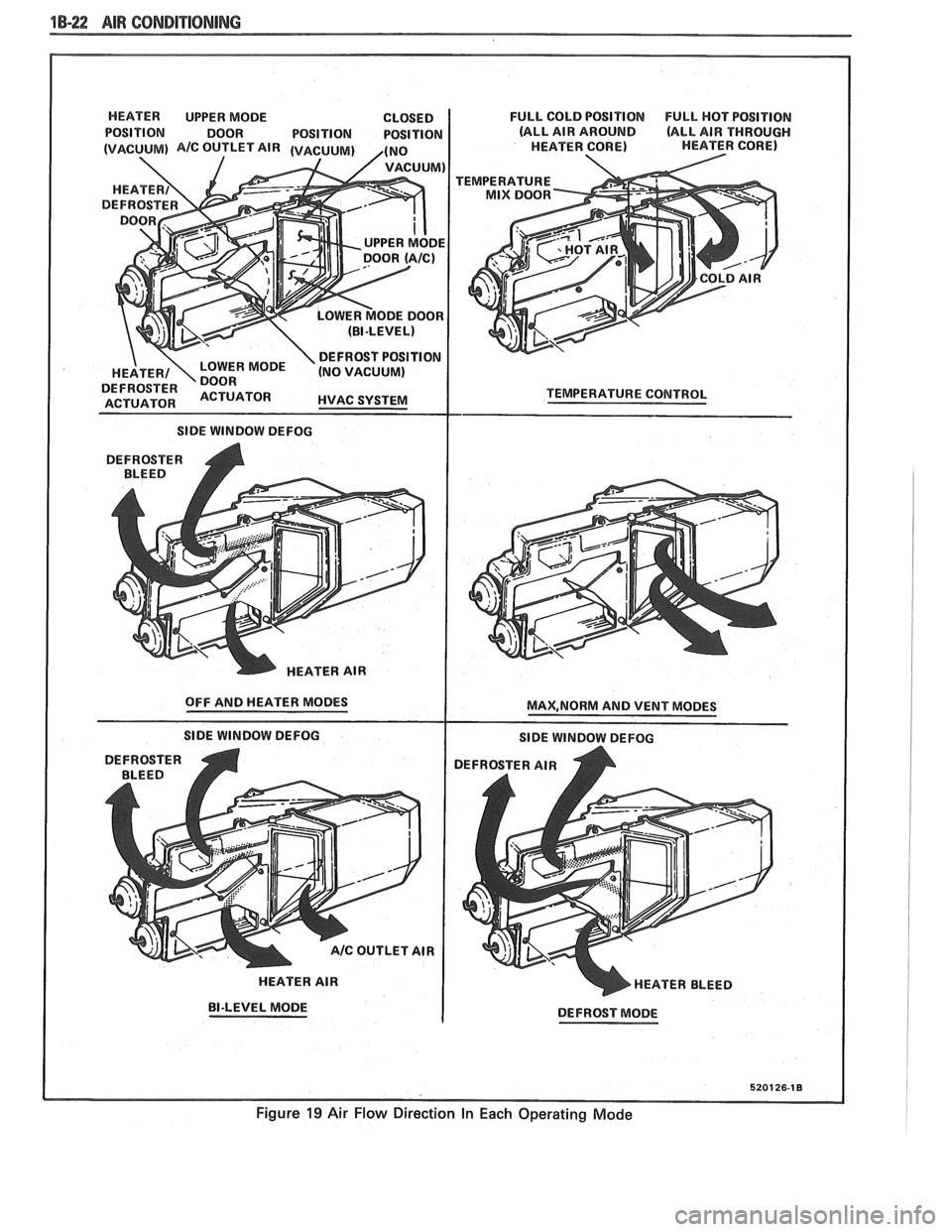
1B-22 AIR CONDITIONING
HEATER UPPER MODE CLOSED
POSITION DOOR POSITION POSITION
I SIDE WINDOW DEFOG
DEFROSTER
A BLEED
HEATER AIR
OFF AND HEATER MODES
SlDE WINDOW DEFOG
HEATER AIR
BI-LEVEL MODE FULL
COLD POSITION
FULL HOT POSITION
(ALL AIR AROUND
(ALL AIR THROUGH
HEATER CORE) HEATER CORE)
TEMPERATURE
TEMPERATURE
COlUTROL
MAX,NORM AND VENT MODES
SlDE WINDOW DEFOG
DEFROSTER AIR
HEATER BLEED
DEFROST MODE
5201 26-1 8
Figure 19 Air Flow Direction In Each Operating Mode
Page 66 of 1825
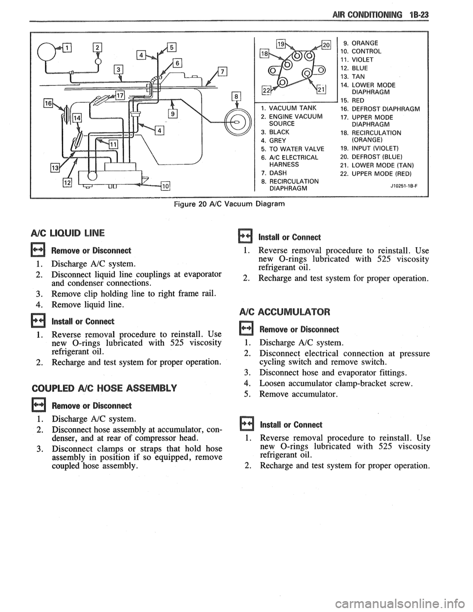
AIR CONDITIONING "18-23
10. CONTROL
14. LOWER MODE
DIAPHRAGM
16. DEFROST DIAPHRAGM
17. UPPER MODE
DIAPHRAGM
18. RECIRCULATION
5. TO WATER VALVE 19. lfVPUT (VIOLET)
6. A/C ELECTRICAL 20. DEFROST (BLUE)
21. LOWER MODE (TAN)
22. UPPER MODE (RED)
8. RECIRCULATION
DIAPHRAGM J~OZ~~-IB-F
Figure 20 AIC Vacuum Diagram
NG LlCbUlB LINE
Remove or Disconnect
1. Discharge A!C system.
2. Disconnect liquid line couplings at evaporator
and condenser connections.
3. Remove clip holding line to right frame rail.
4. Remove liquid line.
lnstall or Conne&
1. Reverse removal procedure to reinstall. Use
new O-rings lubricated with
525 viscosity
refrigerant oil.
2. Recharge and test system for proper operation.
COUPLED NC HOSE ASSEMBLY
Remove or Disconne&
lnstall or Conne&
1. Reverse removal procedure to reinstall. Use
new O-rings lubricated with
525 viscosity
refrigerant oil.
2. Recharge and test system for proper operation.
Remove or Disconnect
1. Discharge A!C system.
2. Disconnect electrical connection at pressure
cycling switch and remove switch.
3. Disconnect hose and evaporator fittings.
4. Loosen accumulator clamp-bracket screw.
5. Remove accumulator.
1. Discharge
NC system.
2. Disconnect hose assembly at accumulator, con- Install or Connect
denser, and at rear of c6mpressor head. 1. Reverse removal procedure to reinstall. Use
3. Disconnect clamps or straps that hold hose new
O-rings lubricated with 525 viscosity
assembly in position if so equipped, remove refrigerant
oil.
coupled hose assembly.
2. Recharge and test system for proper operation.
Page 67 of 1825
1B-24 AIR CONDPTIBNING
EVAPORATOR CORE
Remove QP Disconnect
1. Discharge A/C system.
2. Remove accumulator.
3. Remove two (2) screws and remove hi-blower
relay terminal.
4. Remove upper case screws.
5. Relocate wiring harness and remove dipstick.
6. Disconnect liquid line fitting.
7. Remove upper case and lift evaporator core out
of case (retain foam wedge).
Install or Connect
1. Reverse removal procedure to reinstall.
2. Recharge and test system for proper operation.
EVAPBRAWORCASE
Remove or Disconnect
1. Remove accumulator.
2. Remove blower motor.
3. Remove evaporator core.
Remove lower case to cowl screws (three driven from engine compartment, three driven from
interior).
Remove case from cowl.
Install or Connect
Reverse removal procedure to reinstall. Rein-
stall or replace gaskets, seal and sealant
removed during disassembly.
Recharge and test system for proper operation.
NG COMPRESSOR (TYPICAL)
Remove or Disconnect
1. Discharge A/C system.
2. Remove fitting block (coupled hose assembly)
bolt at rear of compressor.
3. Remove mounting bracket bolt(s) .
4. Remove drive belt (route lower loop behind har-
monic balancer to gain additional slack if
required).
5. Remove compressor. If complete compressor is
to be replaced, transfer usable switches, etc. to
new compressor.
Install or Connect
1. Reverse removal
procedure to reinstall. Use
new O-rings lubricated with
525 viscosity
refrigerant oil. Refer to Section
6B for drive belt
tension.
2. Evacuate and recharge system.
CONDENSER
a Remove or Disconnect
1. Discharge A/C system.
2. Disconnect coupled hose and liquid line fittings.
3, Remove screws retaining top radiator shield.
4. Remove top condenser retaining screws.
5. Carefully move (tilt) radiator rearward and lift
condenser out of radiator support.
6. Transfer brackets and mounts to new condenser
if replacement is necessary.
Install or Connect
1. Reverse removal procedure to reinstall. Use
new O-rings lubricated with
525 viscosity
refrigerant oil.
2. Recharge and test system for proper operation.
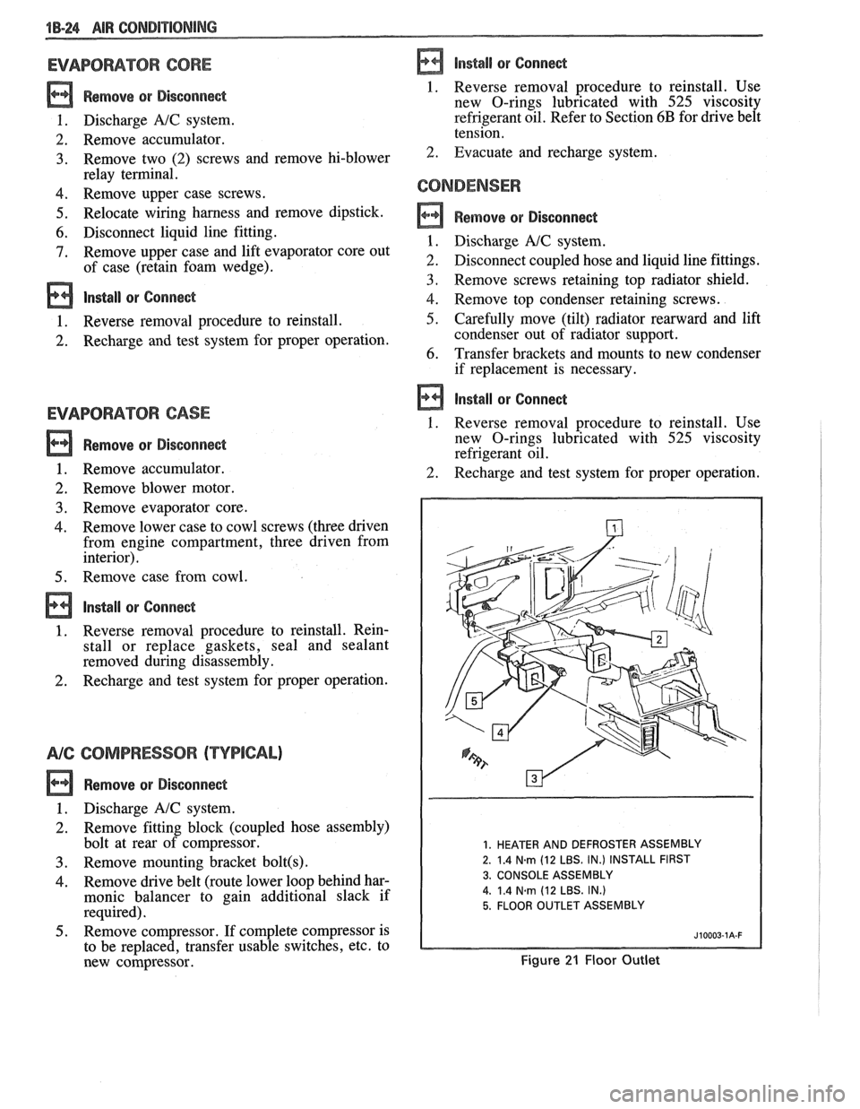
1. HEATER AND DEFROSTER ASSEMBLY
2. 1.4
N.m (12 LBS. IN.) INSTALL FIRST
3. CONSOLE ASSEMBLY
4.
1.4 Narn (12 LBS. IN.)
5. FLOOR OUTLET ASSEMBLY
Figure 21 Floor Outlet
Page 68 of 1825
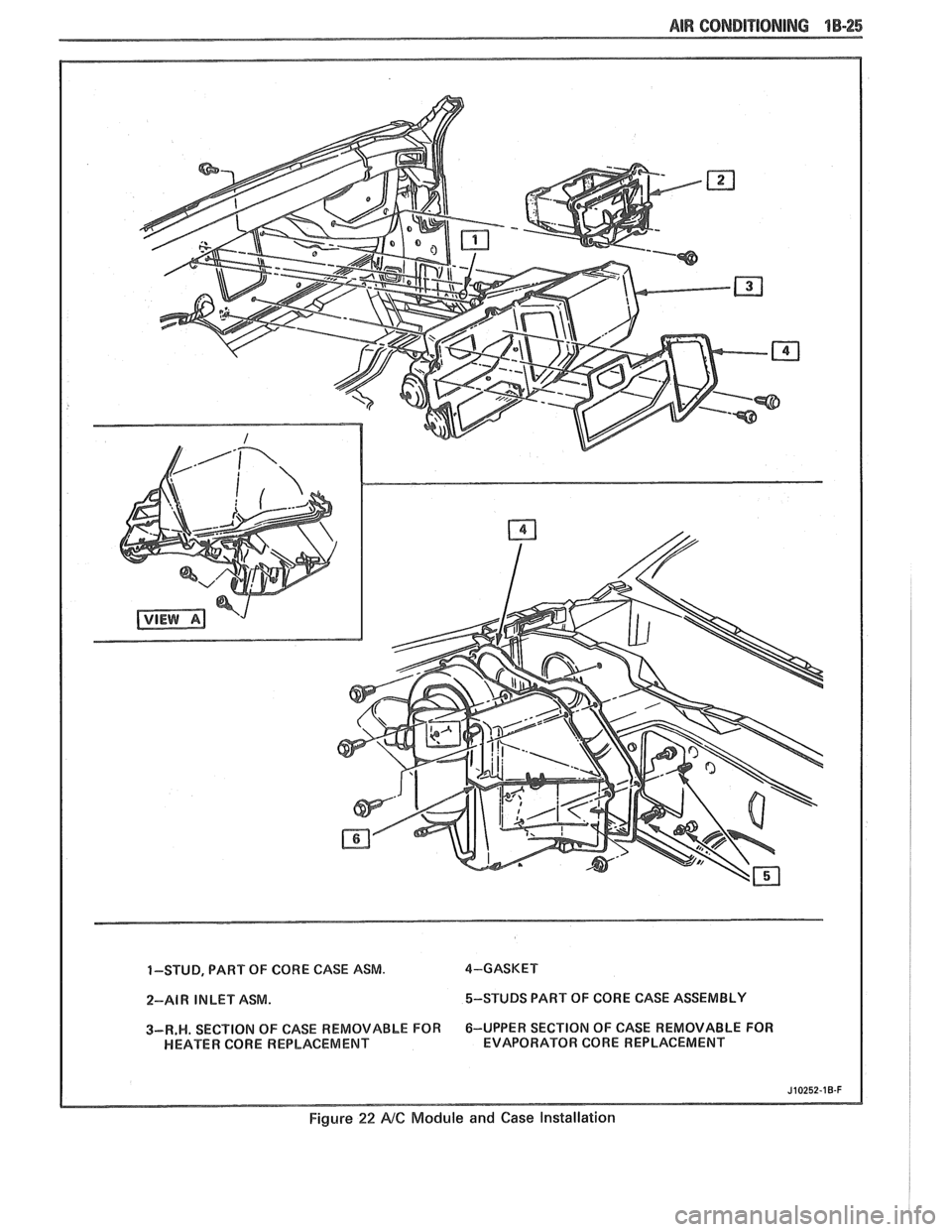
1-STUD, PART OF CORE CASE ASM. 4-GASKET
2-A1 W IN LET ASM. 5-STUDS
PART OF CORE CASE ASSEMBLY I 3-R.W. SECT ION OF CASE REMOVABLE FOR 6-UPPER
SECTION OF CASE REMOVABLE FOR
HEATER CORE REPLACEMENT EVAPORATOR CORE REPLACEMENT
Figure 22 NC Module
and Case lnstallarion
Page 69 of 1825
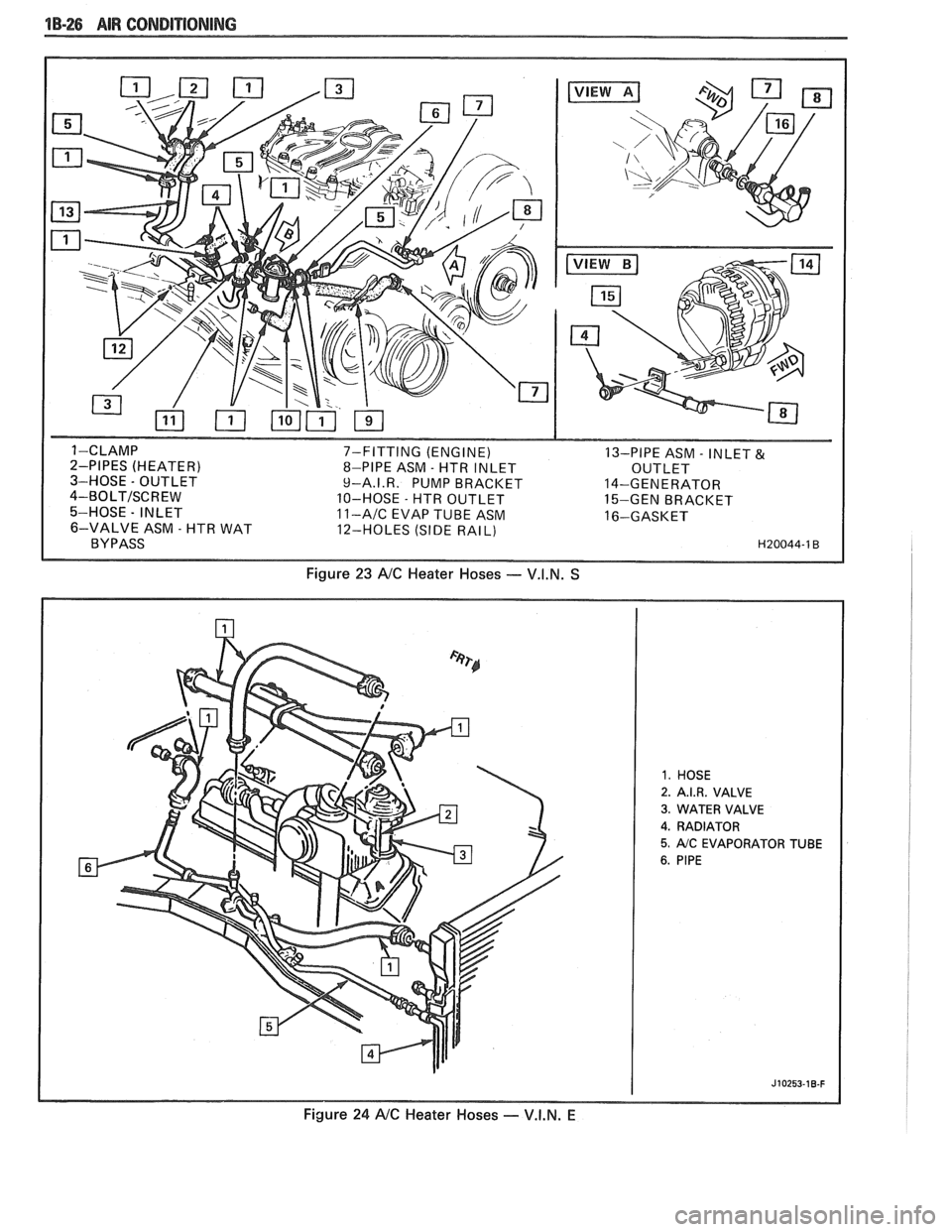
1B-26 AIR CONDITIONING
7-FITTING (ENGINE)
13-PIPE ASM - INLET & 8-PIPE ASM - HTR INLET
OUTLET
9-A.I.R. PUMP BRACKET 14-GENERATOR
10-HOSE
- HTR OUTLET
15-GEN BRACKET 11-AIC EVAP TUBE ASM 16-GASKET
12-HOLES (SIDE RAIL)
Figure 23 NC Heater Hoses - V.I.N. S
2. A.I.R. VALVE
3. WATER VALVE
4. RADIATOR
5. AIC EVAPORATOR TUBE
Figure 24 NC Heater Hoses - V.I.N. E
Page 70 of 1825
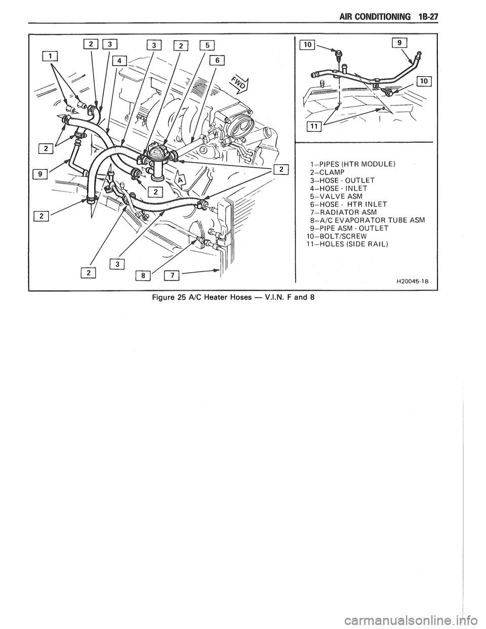
1-PIPES (HTR MODULE)
2-CLAMP
3-HOSE
- OUTLET
4-HOSE
- INLET
5-VALVE ASM
6-HOSE
- HTR INLET
7-RADIATOR ASM
8-A/C EVAPORATOR TUBE ASM
9-PIPE ASM
- OUTLET
10-BOLTISCREW
11-HOLES (SIDE RAIL)
Figure 25 A/C Heater Hoses - V.I.N. F and 8