PONTIAC FIERO 1988 Service Manual PDF
FIERO 1988
PONTIAC
PONTIAC
https://www.carmanualsonline.info/img/50/57415/w960_57415-0.png
PONTIAC FIERO 1988 Service Manual PDF
Trending: maintenance, wiper size, distributor order, change time, oil type, high beam, rear view mirror
Page 71 of 1825
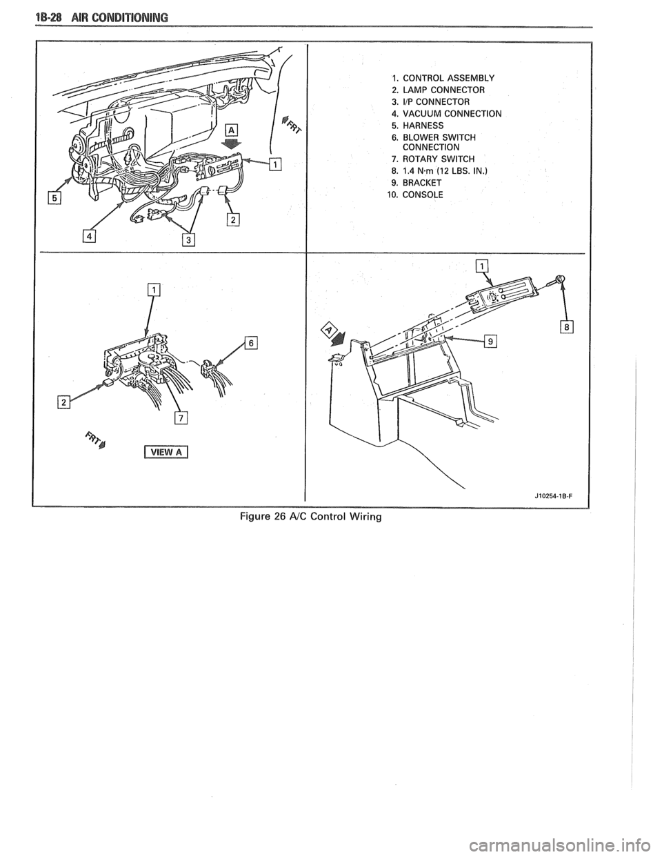
"1-28 AIR CONDITIORIBNG
Figure 26 AtC Control Wiring
Page 72 of 1825
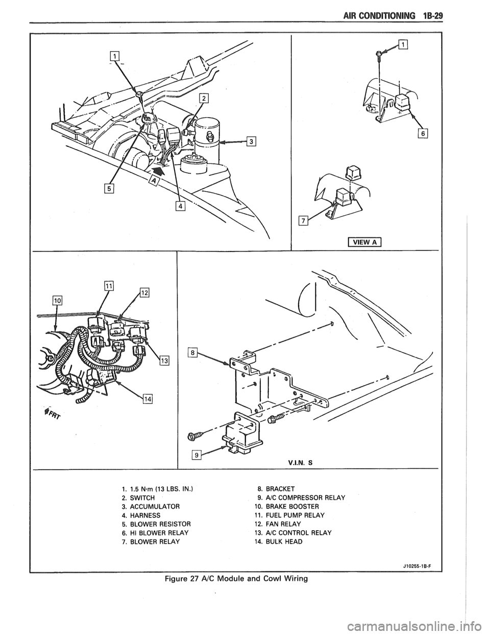
AIR CONDITIONING 1B-29
1. 1.5 N.m (13 LBS. IN.) 8. BRACKET
2. SWITCH
9. AJC COMPRESSOR RELAY
3. ACCUMULATOR 10. BRAKE BOOSTER
4. HARNESS 11.
FUEL PUMP RELAY
5. BLOWER RESISTOR 12. FAN RELAY
6. HI BLOWER RELAY 13. AJC CONTROL
RELAY
7. BLOWER RELAY 14. BULK HEAD
J10255-18-F
Figure 27 A/C Module and Cowl Wiring
Page 73 of 1825
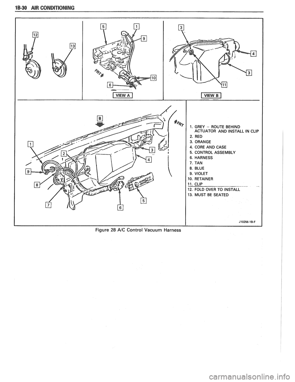
18-38 AIR CONDITIONING
ACTUATOR AND INSTALL IN CLIP
4. CORE AND CASE
5. CONTROL ASSEMBLY
10. RETAINER
12. FOLD OVER TO INSTALL
13. MUST BE SEATED
Figure 28 AIC Control Vacuum Harness
Page 74 of 1825
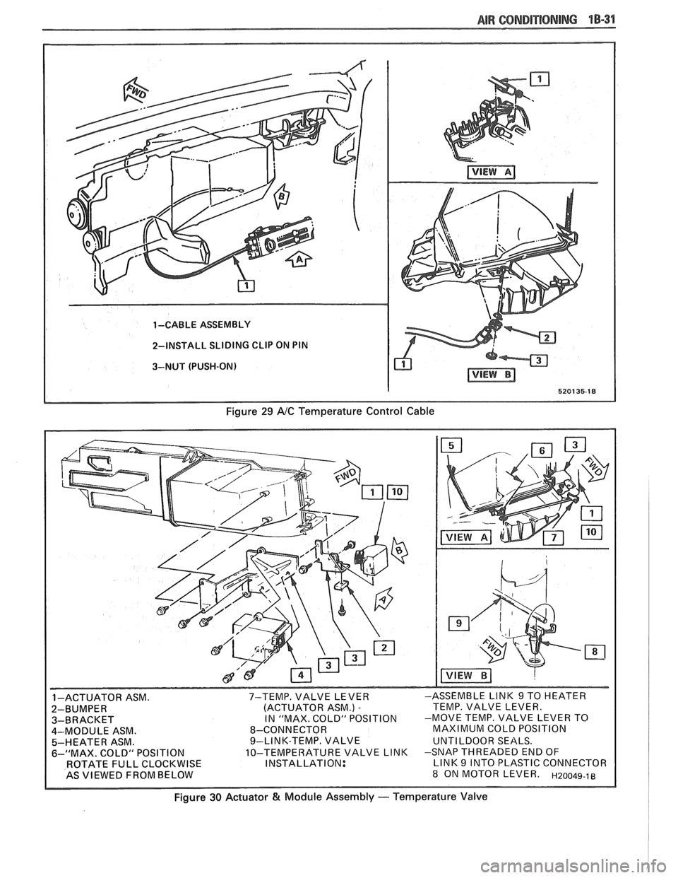
AIR 68RIDIT18NING 1 B-31
1 -CABLE ASSEMBLY
2-INSTALL SLIDING
CLIP ON PIN
3-NUT (PUSH-ON)
520135-18
Figure 29 NC Temperature Control Cable
INSTALLATION:
Figure 30 Actuator & Module Assembly - Temperature Valve
Page 75 of 1825
1B-32 AIR CONDITIONING
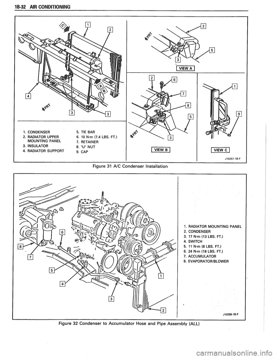
1. CONDENSER 5. TIE BAR
2. RADIATOR UPPER
6. 10 N-rn (7.4 LBS. FT.) MOUNTING PANEL 7. RETAINER
3. INSULATOR 8. "U" NUT
4. RADIATOR SUPPORT 9. CAB
I I J10257-1B-F
Figure 31 A/C Condenser Installation
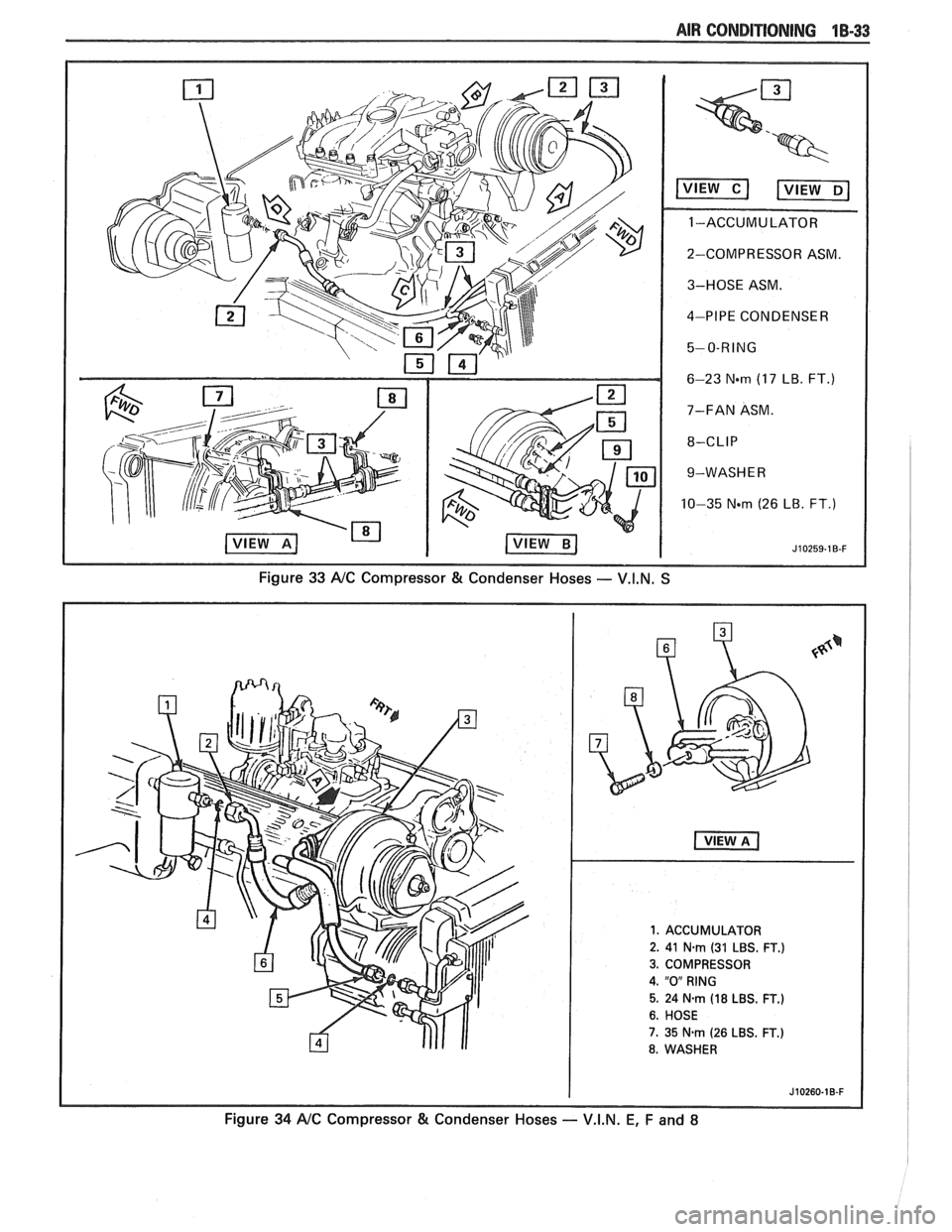
1. RADIATOR MOUNTING PANEL
2. CONDENSER
3.
17 N.rn (13 LBS. FT.)
4. SWITCH
5. 11 N-rn (8 LBS. FT.)
6. 24 Nsm (18 LBS. FT.)
7. ACCUMULATOR
8. EVAPORATORIBLOWER
Figure 32 Condenser to Accumulator Hose and Pipe Assembly (ALL)
Page 76 of 1825
AIR CONDITIONING 18-33
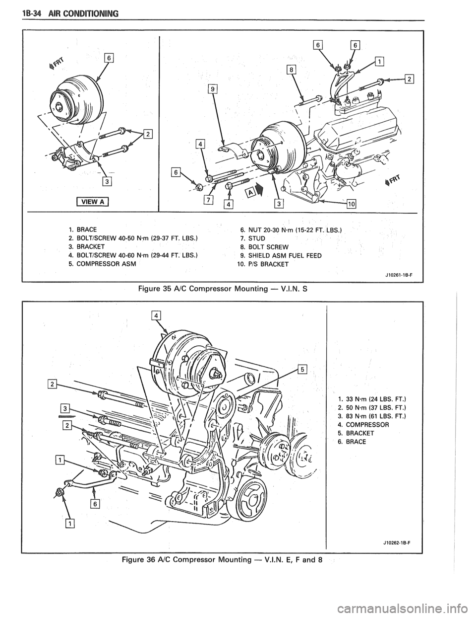
2-COMPRESSOR ASM.
3-HOSE ASM.
4-PIPE CONDENSER
6-23
N-m (17 LB. FT.)
7-FAN ASM.
9-WASH E
R
10-35 Nm (26 LB. FT.)
Figure 33 A/C Compressor & Condenser Hoses -- V.I.N. S
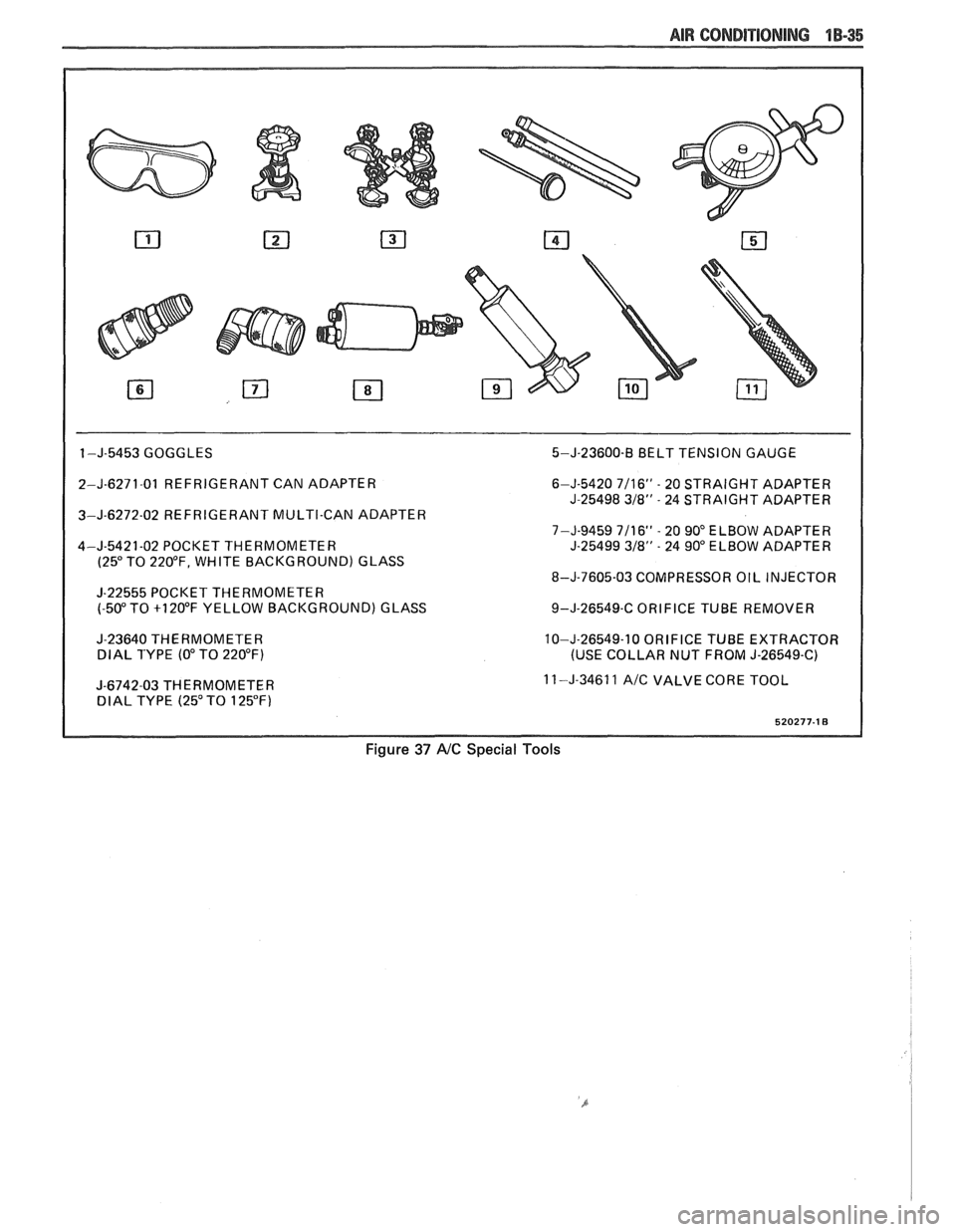
1. ACCUMULATOR
2. 41
N-rn (31 LBS. FT.)
3. COMPRESSOR
4. "0" RING
5. 24 N.m (18 LBS. FT.)
6. HOSE
7. 35 N.rn (26 LBS. FT.)
8. WASHER
Figure 34 A/C Compressor & Condenser Hoses - V.I.N. E, F and 8
Page 77 of 1825
1 B-3 AIR CONDITIONING
1. BRACE 6. NUT 20-30 N.rn (15-22 FT. LBS.)
2.
BOLTISCREW 40-50 Nm (29-37 FT. LBS.)
7. STUD
3. BRACKET 8. BOLT SCREW
4.
BOLTISCREW 40-60 Nm (29-44 FT. LBS.) 9. SHIELD ASM FUEL FEED
5. COMPRESSOR ASM
10. PIS BRACKET
Figure 35 NC Compressor Mounting - V.I.N. S
1. 33 N.rn (24 LBS. FT.)
2. 50 Nm (37 LBS. FT.)
3. 83 N.rn (61 LBS. FT.)
4. COMPRESSOR
J10262-10-F
Figufe 36 NC Compressor Mounting - V.I.N. E, F and 8
Page 78 of 1825
AIR CONDITIONING 1B-35
I
1 -J-5453 GOGGLES 5-J-23600-B BELT TENSION GAUGE
2-J-6271-01 REFRIGERANT CAN ADAPTER
3-J-6272-02 REFRIGERANT MULTI-CAN ADAPTER
4-J-5421-02 POCKET THERMOMETER
(25" TO 220°F, WHITE BACKGROUND) GLASS
J-22555 POCKET THERMOMETER
(-50" TO +I 20°F YELLOW BACKGROUND) GLASS
J-23640 THERMOMETER
DlAL TYPE (0" TO 220°F)
I
J-6742-03 THERMOMETER DlAL TYPE (25" TO 125°F) 6-J-5420
7/16" - 20
STRAIGHT ADAPTER
J-25498
318" - 24 STRAIGHT ADAPTER
7-J-9459 7/16"
- 20 90" ELBOW ADAPTER
J-25499 318" - 24 90" ELBOW ADAPTER
8-J-7605-03 COMPRESSOR OIL INJECTOR
9-J-26549-C ORIFICE TUBE REMOVER
10-J-26549-10 ORIFICE TUBE EXTRACTOR
(USE COLLAR NUT FROM J-26549-C)
11 -J-34611
A/C VALVE CORE TOOL
Figure 37 AIC Special Tools
Page 79 of 1825
Page 80 of 1825
W-4 AIR CONDITIONING COMPRESSOR OVERHAUL 1 Dl-l
SECTION 1 Dl
R COND NG COMPRESSOR
OVERHAUL
For Compressor REMOVAL AND INSTALLATION, see Air Conditioning Section 1B. For
DISCHARGING, ADDING OIL, EVACUATING AND CHARGING PROCEDURES FOR
A/C
SYSTEMS, see Air Conditioning Section 1B.
CONTENTS
General Description ............................... 1D1-1
Service Procedures .................................. 1D1-4
Minor Repair Procedures ....................... 1D1-4
Clutch Plate and Hub Assembly ............... 1D1-4
Clutch Rotor and Bearing: Four-Pole
Clutch
..................................................... 1D1-5
Clutch Rotor and Bearing: Six-Pole
Clutch
.......................... ... ....................... 1 D 1-7
Clutch Coil and Pulley Rim ...................... 1 D 1 - 10
Major Repair Procedures ....................... 1D1-12
Shaft Seal .................................................. 1Dl-12
Seal Leak Detection ........................... .... 1D1-12
Replacement (On Car) ........................... 1 D 1- 12
Replacement (Off Car)
........................... 1 D 1 - 13
Pressure Relief Valve
................................. 1 D 1 - 13
Nigh Pressure Cut-Off Switch
................... 1 D 1 - 13
Front Head and 0-Ring
............................ 1 D 1 - 14
Thrust and Belleville Washers
................... 1 D 1 - 16
Main Bearing
.............................................. 1 D 1- 16
Shell and 0-Ring
....................................... 1D 1- 17
Discharge Valve Plate and Retainer
......... 1 D 1 - 18
Cylinder and Shaft Assembly
.................... 1 D 1 - 19
Leak Testing (External and Internal)
........ 1D1- 19
Special Tools ..................................... ... .. 1D1-21
GENERAL DESCRIPTION
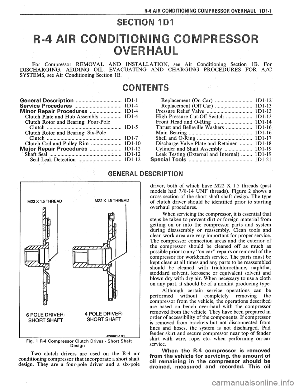
M22 X 1.5 THREAD M22 X 1.5 THREAD
6 POLE DRIVER- 4 POLE DRIVER-
SHORT SHAFT SHORT SHAFT
J20001.1 Dl
Fig. 1 R-4 Compressor Clutch Drives - Short Shaft
Desian
driver, both of which have M22 X 1.5 threads (past
models had 7/8-14
UNF threads). Figure 2 shows a
cross section of the short shaft shaft design. The type
of clutch driver should be identified prior to starting
overhaul procedures.
When servicing the compressor, it is essential that
steps be taken to prevent dirt or foreign material from
getting on or into the compressor parts and system
during disassembly or reassembly. Clean tools and
clean work area are very important for proper service.
The compressor connection areas and the exterior of
the compressor should be cleaned off as much as
possible prior to any "on car" repairs or removal of the
compressor for workbench service. The parts must be
kept clean at all times and any parts to be reassembled
should be cleaned with trichloroethane, naphtha,
stoddard solvent, kerosene or equivalent solvent and
blown dry with dry air. When necessary to use a cloth
on any part, it should be of a nonlint producing type.
Although certain service operations can be
performed without completely removing the
compressor from the vehicle, the operations described
are based on bench over-haul with the compressor
removed from the vehicle. They have been prepared in
order of accessibility of the components. If compressor
is removed from brackets but not disconnected from
lines and hoses, the system is not discharged. Pad
fender skirt and secure compressor near top of fender
skirt with wire, rope,
etc, when performing on-car
service.
., When the R-4 compressor is removed Two 'lutch drivers are wed On the R-4 air from the vehicle for servicing, the amount of conditioning compressor that incorporate a short shaft oil remaining in the should be design. They are a four-pole driver and a six-pole drained, measured and recorded. This oil
Trending: headrest, service schedule, wiring, fuel fill door release, rear view mirror, brakes, tailgate
