RENAULT KANGOO 1997 KC / 1.G Chassis Owner's Manual
Manufacturer: RENAULT, Model Year: 1997, Model line: KANGOO, Model: RENAULT KANGOO 1997 KC / 1.GPages: 105
Page 21 of 105
FRONT AXLE
Stub axle carrier bearing
31
79057S
REFITTING
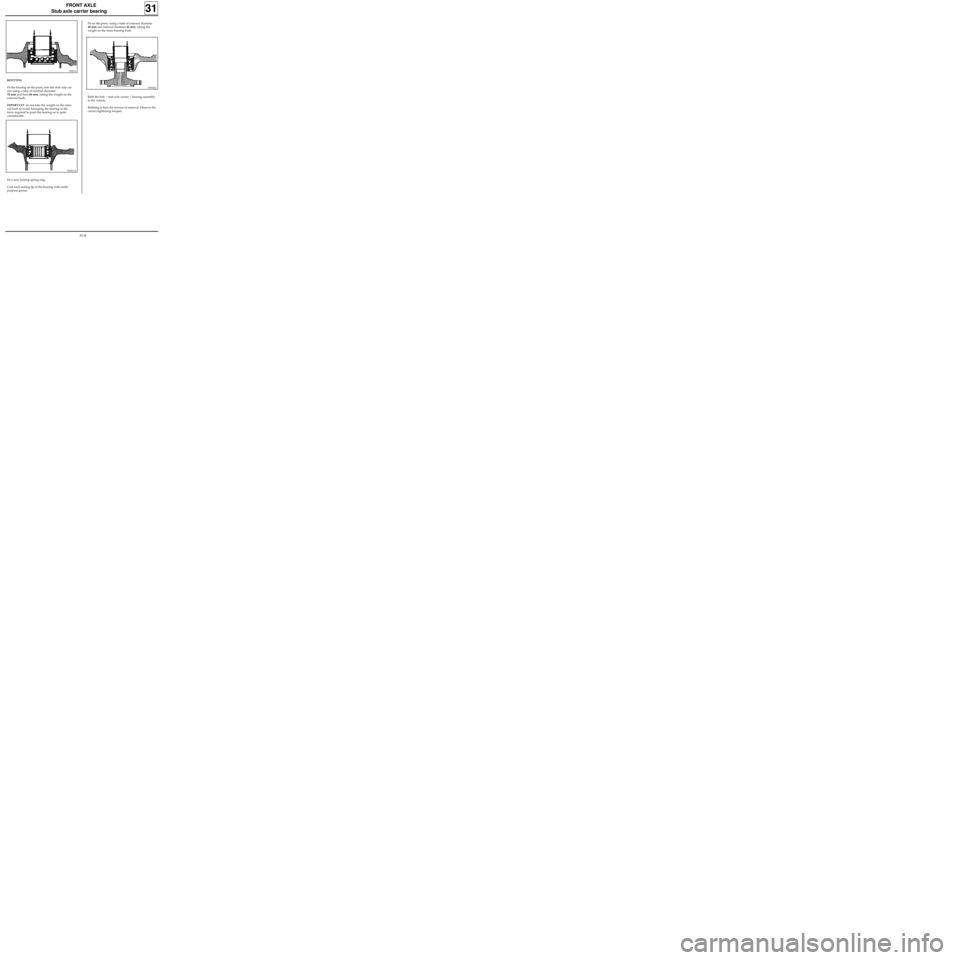
Fit the bearing on the press, into the stub axle car-
rier using a tube of external diameter
70 mm and bore 66 mm, taking the weight on the
external bush.
IMPORTANT: do not take the weight on the inter-
nal bush to avoid damaging the bearing as the
force required to push the bearing on is quite
considerable.
79058-1S
Fit a new locking spring ring.
Coat each sealing lip of the bearing with multi-
purpose grease.
Fit on the press, using a tube of external diameter
48 mm and internal diameter 42 mm, taking the
weight on the inner bearing bush.
85902S1
Refit the hub / stub axle carrier / bearing assembly
to the vehicle.
Refitting is then the reverse of removal. Observe the
correct tightening torques.
31-8
Page 22 of 105
Spring compressor
FRONT AXLE
Spring and shock absorber assembly
31
Shock absorber base mounting bolt 18
Rebound stop nut 6
Wheel bolts 9
REMOVAL
Put the vehicle on a four post lift.
Remove:
- the wheels,
- the shock absorber base mounting bolts.
NOTE : release the ABS sensor wiring if this is
fitted on the base of the shock absorber.
Remove the upper shock absorber nut in the
engine compartment.
Remove the shock absorber and spring assembly.
TIGHTENING TORQUES (in daN.m)
EQUIPMENT REQUIRED
Replacing a shock absorber
When replacing a shock absorber, fit it in a vice
and compress the spring using the spring
compressor tool.
Remove the spring retaining nut.
Remove the spring and the intermediate parts.
If necessary, replace the shock absorber pad and
the rotating stop.
When refitting, ensure all components are
replaced in the correct location and then
decompress the spring.
NOTE : apply grease between the ends of the
spring and its stops.
REFITTING
Refitting is then the reverse of removal. Observe
the correct tightening torques.
31-9
Page 23 of 105
FRONT AXLE
Anti-roll bar
REFITTING
Refit:
- the rubber mounting nuts using tool
Sus. 1414,
31
REMOVAL
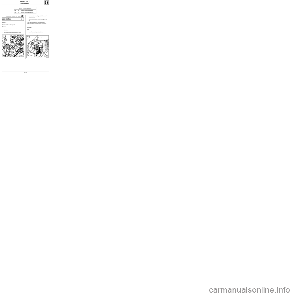
Put the vehicle on a four post lift.
Remove:
- the two lower bolts from the exhaust
downpipe,
- the two sub-frame reinforcements (4 bolts),
12993-1R
Central bearing bolt 3
Rubber mounting nut 1.5
TIGHTENING TORQUES (in daN.m)
SPECIAL TOOLING REQUIRED
Sus. 1413 Central bearing compressor
Sus. 1414 Rubber mounting compressor
- the two rubber mounting nuts at the ends of
the anti-roll bar,
- the two bolts from the central bearings on the
bar.
Check the condition of the bearings and the
rubber mountings and replace them if necessary.
12992R
31-10
Page 24 of 105
FRONT AXLE
Anti-roll bar
31
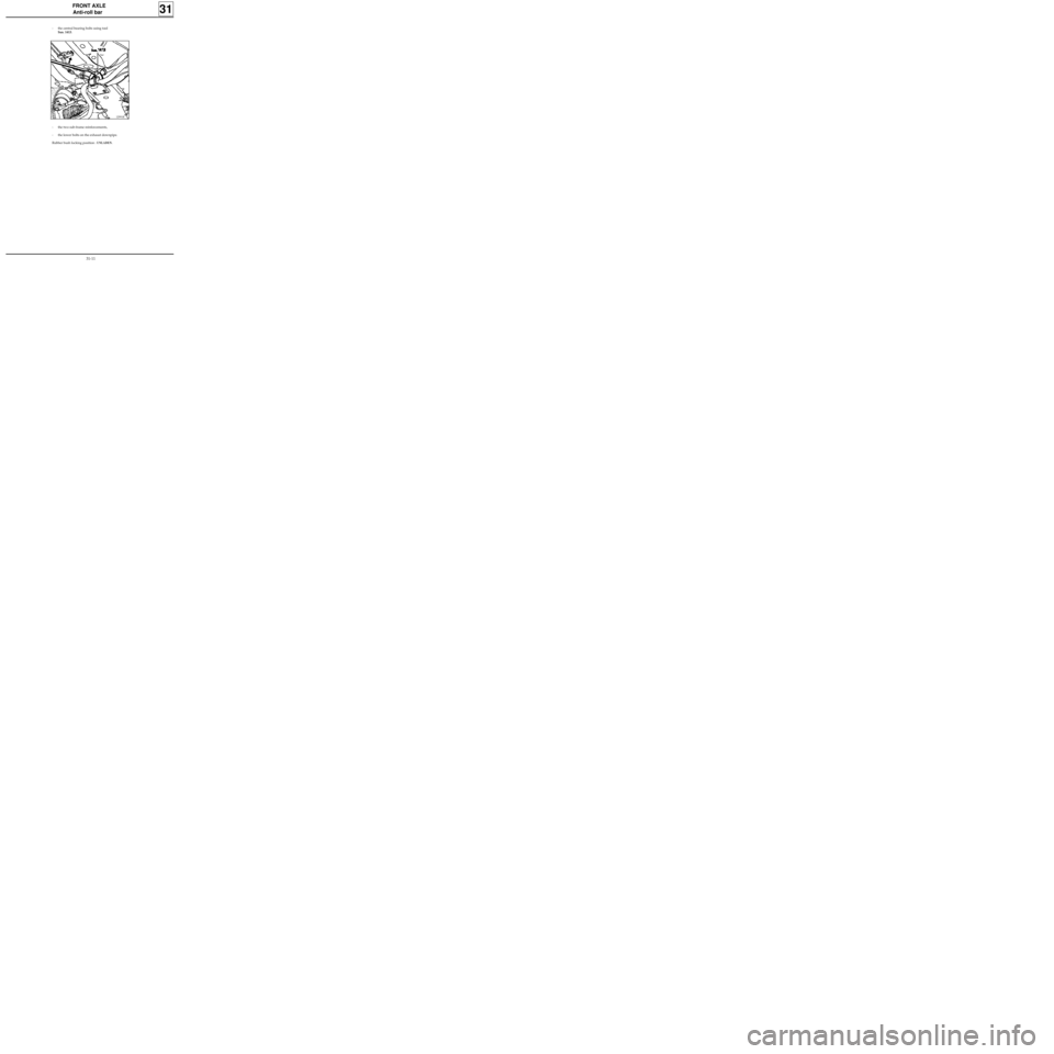
- the central bearing bolts using tool
Sus. 1413.
12991R
- the two sub-frame reinforcements,
- the lower bolts on the exhaust downpipe.
Rubber bush locking position :
UNLADEN.
31-11
Page 25 of 105
FRONT AXLE
Engine sub-frame
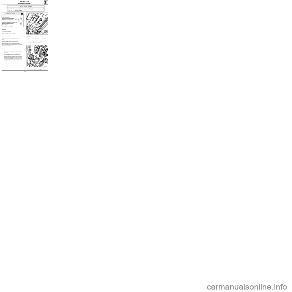
Remove:
- the two nuts for the steering rack heat shield,
- the mounting nuts for the steering rack and
attach it to the exhaust manifold.
31
12988R
SPECIAL TOOLING REQUIRED
Mot. 1040 -01 Dummy sub-frame for removing/refitting engine/transmission assembly
T. Av. 476 Ball joint extractor
REMOVAL
Disconnect the battery.
Put the vehicle on a two post lift.
Remove the wheels.
Disconnect the track rod ends using tool T. Av.
476.
Remove the key on the stub axle carrier.
Release but do not remove the mudguards to
reach the upper bolt on the sub-frame - side mem-
ber tie rod and remove it.
Remove:
- the exhaust downpipe and attach the catalytic
converter,
- the bolt (engine side) for the engine tie bar.
- the gear control by removing the two bolts at
the ends of the control. To do this, the cataly-
tic converter heat shield must be removed and
the gaiter on the gearbox side must also be re-
moved.
TIGHTENING TORQUES (in daN.m)
Wheel bolts 9
Track rod end nut 3.7
Steering universal joint bolt 2.5
Sub-frame mounting bolt front Ø10 6
rear Ø 12 10.5
Sub-frame - side member tie rod nut 3
Key nut on stub axle carrier 5.5
Engine tie bar 6.5
Steering box mounting bolt 5
Fit tool Mot. 1040-01 under the engine sub-frame.
12993-1R1
31-12
Page 26 of 105
FRONT AXLE
Engine sub-frame
31
Lower the lift until the tool touches the ground.
Remove the sub-frame mounting bolts.
Carefully raise the lift.
REFITTING
Systematically renew the engine sub-frame moun-
ting bolts and ensure they are tightened to the
correct torque.
Refitting is the reverse of removal.
NOTE : the engine sub-frame is fitted to the body
in the following manner.:
- fit 2 pins in place of the front mounting bolts,
- offer up the sub-frame,
- tighten, but do not lock, the rear mounting
bolts (begin with the longest rear right hand
bolt),
- replace the pins with mounting bolts at the
front,
- tighten the four mounting bolts to the correct
torque, beginning at the rear,
- ensure the heat shields are correctly refitted.
31-13
Page 27 of 105
REAR AXLE
Rear axle assembly
TIGHTENING TORQUES (in daN.m)
Bearing mounting nut 11
Wheel bolt 9
Shock absorber base bolt 8.5
REMOVAL
Put the vehicle on a two post lift.
Fit the pedal press.
Remove:
- the two lower shock absorber mountings,
- the brake pipes,
- the compensator control,
- the central heat shield,
- the handbrake cables, disconnecting them
from the central control,
Unclip the cables from the fuel tank.
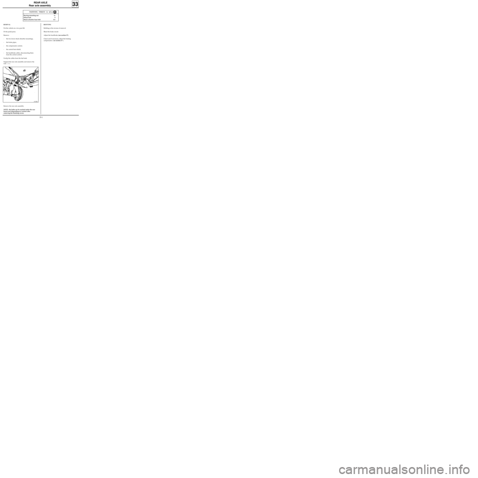
Support the rear axle assembly and remove the
nuts ( 1 ).
Remove the rear axle assembly.
NOTE : the bolts can be reached under the rear
bench seat (depending on version) after
removing the blanking covers.
REFITTING
Refitting is the reverse of removal.
Bleed the brake circuit.
Adjust the handbrake (see section 37).
Check and if necessary adjust the braking
compensator ( see section 37 ).
33
13132R
33-1
Page 28 of 105
98991
REAR AXLE
Brake drum
Remove:
- the nut and stub axle washer,
- the drum.
The two brake drums must be of the same diameter, if one is reground, the other must also be reground.
Never exceed the diameter marked on the drum.
SPECIAL TOOLING REQUIRED
Emb. 880 Inertia extraction tool
Rou. 943 Hub cover plug extractor
TIGHTENING TORQUES (in daN.m)
Wheel bolts 9
Hub nut 17.5
REMOVAL
Remove the hub plug using tools Rou. 943 +
Emb. 880.
Release the handbrake, slacken the secondary
handbrake cables to allow the lever to move back.
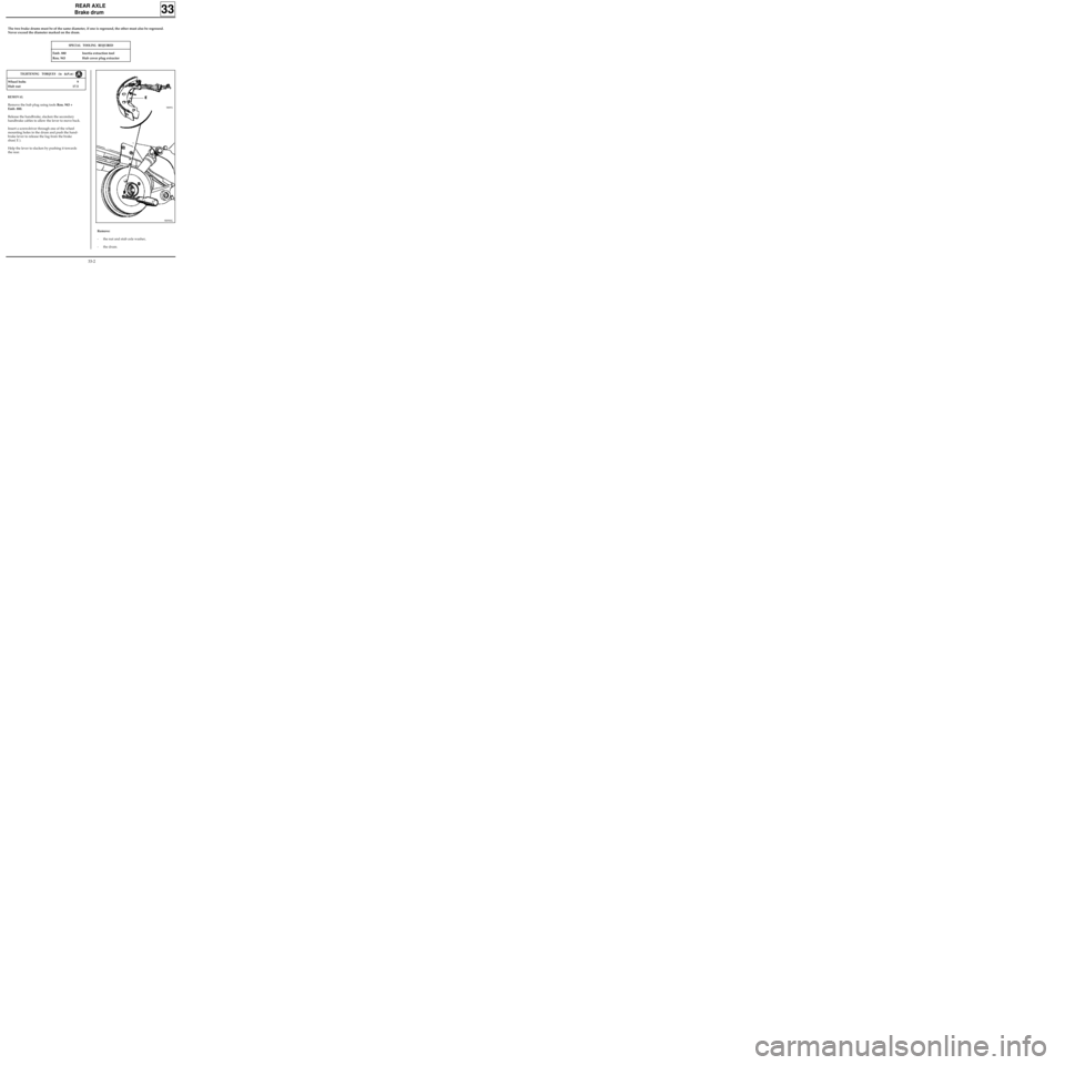
Insert a screwdriver through one of the wheel
mounting holes in the drum and push the hand-
brake lever to release the lug from the brake
shoe( E ).
Help the lever to slacken by pushing it towards
the rear.
33
98990G
33-2
Page 29 of 105
REAR AXLE
Brake drum
REFITTING
Remove all dust from the drum and the linings
using brake cleaner.
Fit:
- the drum,
- the washer and the nut, which must be torque
tightened,
- the plug.
Adjust:
- the linings by repeatedly pressing the brake
pedal,
- the handbrake (see section 37 "Controls").
33
33-3
Page 30 of 105
REAR AXLE
Brake cylinder
REFITTING
Remove all dust from the drums and the linings
using brake cleaner.
Refitting is the reverse of removal.
Bleed the braking circuit (see section 38).
Adjust the linings by repeatedly pressing the
brake pedal.
Check the cut-out pressure (see section 37
"Controls").
TIGHTENING TORQUES (in daN.m)
Wheel bolts 9
Hub nut 17.5
Bleed screw 0.5 to 0.8
Pipe bolt 1.7
REMOVAL
Remove:
- the drum (see corresponding section),
- the upper return spring (see paragraph
"Brake linings").
Separate the shoes.
Slacken:
- the rigid pipe union on the wheel cylinder
using a pipe wrench,
- the two cylinder mounting bolts on the
backing plate and remove it.
Check the condition of the shoes. If they have
traces of oil on them, renew them.
33
33-4