RENAULT KANGOO 1997 KC / 1.G Engine And Peripherals Workshop Manual
KANGOO 1997 KC / 1.G
RENAULT
RENAULT
https://www.carmanualsonline.info/img/7/1731/w960_1731-0.png
RENAULT KANGOO 1997 KC / 1.G Engine And Peripherals Workshop Manual
Trending: fuel filter, weight, tow, oil filter, fuse, air bleeding, wheel torque
Page 131 of 208
ANTIPOLLUTION
Fuel vapour rebreathing
14
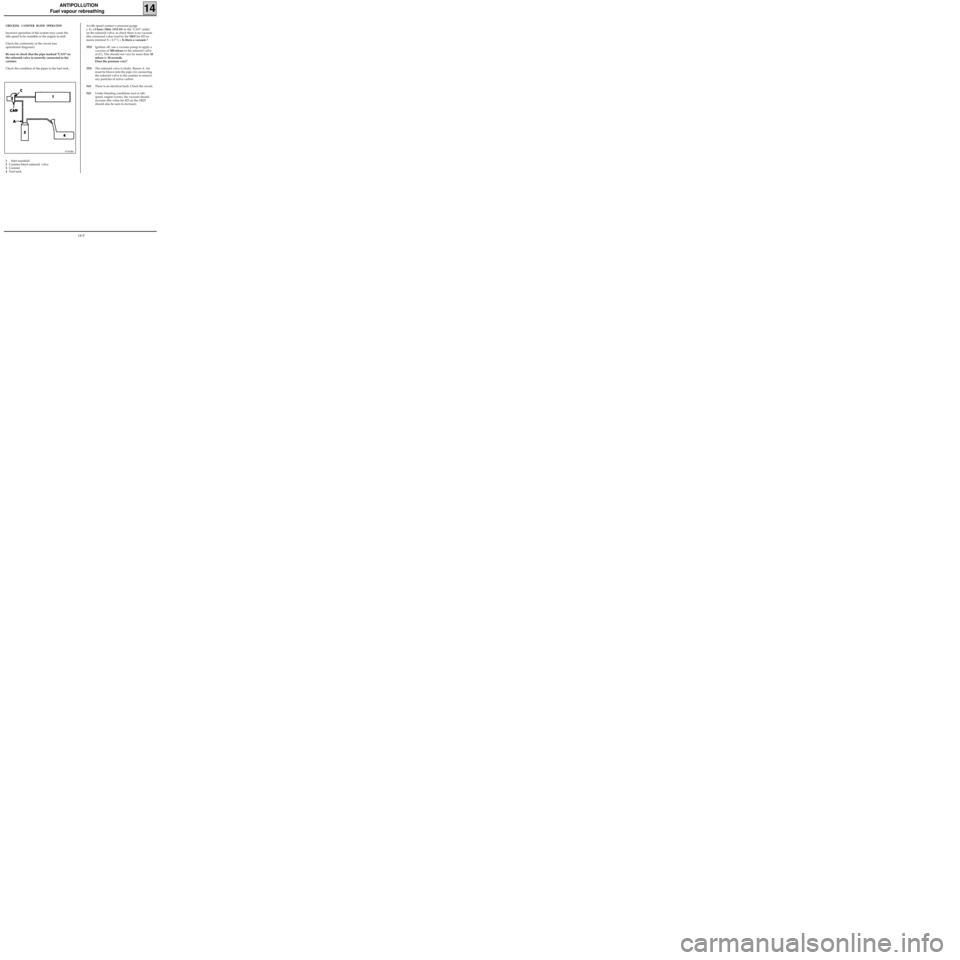
CHECKING CANISTER BLEED OPERATION
Incorrect operation of the system may cause the
idle speed to be unstable or the engine to stall.
Check the conformity of the circuit (see
operational diagrams)
Be sure to check that the pipe marked "CAN" on
the solenoid valve is correctly connected to the
canister.
Check the condition of the pipes to the fuel tank.
97393R6
1Inlet manifold
2Canister bleed solenoid valve
3Canister
4Fuel tankAt idle speed connect a pressure gauge
(- 3 ; +3 bars) (Mot. 1311-01) to the "CAN" outlet
on the solenoid valve, to check there is no vacuum
(the command value read by the
XR25 for #23 re-
mains minimal X = 0.7 % ). Is there a vacuum ?
YESIgnition off, use a vacuum pump to apply a
vacuum of 500 mbars to the solenoid valve
at (C). This should not vary by more than 10
mbars in 30 seconds.
Does the pressure vary?
YESThe solenoid valve is faulty. Renew it. Air
must be blown into the pipe (A) connecting
the solenoid valve to the canister to remove
any particles of active carbon.
NOThere is an electrical fault. Check the circuit.
NOUnder bleeding conditions (not at idle
speed, engine warm), the vacuum should
increase (the value for #23 on the XR25
should also be seen to increase).
14-5
Page 132 of 208
ANTIPOLLUTION
Fuel vapour rebreathing
14
LOCATION-REMOVAL OF COMPONENTS
CANISTER BLEED SOLENOID VALVE
(1)
E7J Engine
It is mounted above the inlet manifold,
underneath the cover
D7F Engine
It is mounted at the front, on the lifting bracket.
13242R2
99939-1R3
REMOVAL OF THE FUEL VAPOUR ABSORBER (1)
This is located in the front right hand wheel arch.
REMOVAL
Disconnect the pipe connecting the canister to the
inlet manifold, from the top of the vehicle.
From the bottom, remove the wheel arch .
Disconnect the pipe at (2) connecting the
canister to the fuel tank.
Remove the three bolts at (3) mounting the
canister (1) then extract it.
13049R
14-6
Page 133 of 208
ANTIPOLLUTION
Oil vapour rebreathing
14
CIRCUIT DIAGRAM
1 Cylinder head cover
2 Inlet manifold
3 Oil vapour rebreathing pipe connected upstream from the throttle body (the circuit is used
for medium and high loads)
4 Oil vapour rebreathing pipe connected downstream from the throttle body
5 Air pipe
6 Throttle body
99932R
D7F Engine
14-7
Page 134 of 208
ANTIPOLLUTION
Oil vapour rebreathing
14
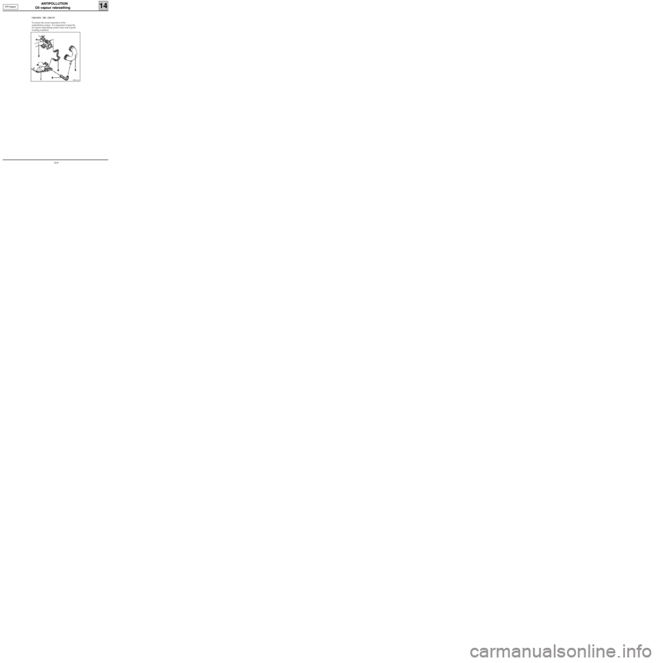
CHECKING THE CIRCUIT
To ensure the correct operation of the
antipollution system, it is important to keep the
oil vapour rebreathing system clean and in good
working condition.
PRC14.2
D7F Engine
14-8
Page 135 of 208
ANTIPOLLUTION
Oil vapour rebreathing
14E7J Engine
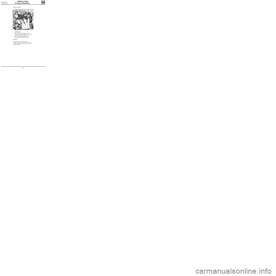
CIRCUIT DIAGRAM
1 Cylinder head
2 Inlet manifold
3 Oil vapour rebreathing pipe connected
upstream from the throttle body (the circuit is
used for medium and high loads)
4 Oil vapour rebreathing pipe connected
downstream from the throttle body
CHECKING
To ensure the correct operation of the
antipollution system, it is important to keep the
oil vapour rebreathing system clean and in good
working condition.
13335R
14-9
Page 136 of 208
ANTIPOLLUTION
Oil vapour rebreathing
14
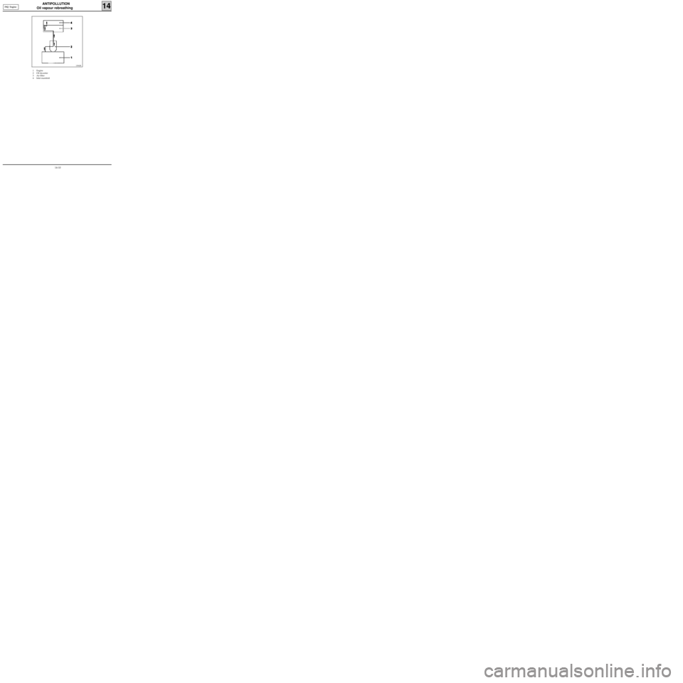
1 Engine
2 Oil decanter
3 Air filter
4 Inlet manifold
13042R
F8Q Engine
14-10
Page 137 of 208
ANTIPOLLUTION
Exhaust gas recirculation (EGR)
14
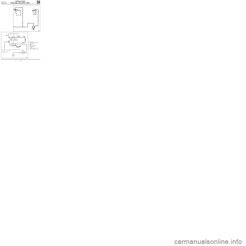
1 EGR valve
2 EGR solenoid (ON/OFF)
3 Vacuum pump
4 Engine
5 Exhaust manifold
6 Inlet manifold
7 Air filter
8 Injection computer
9 Coolant temperature sensor
13046R
F8Q Engine
13045R
14-11
Page 138 of 208
ANTIPOLLUTION
Exhaust gas recirculation (EGR)
14
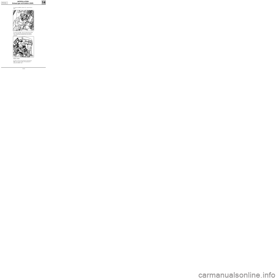
SPECIAL NOTES
In order to remove the steel pipe connecting the
EGR valve to the air filter, it is necessary to
remove the
EGR valve .
12871R1
F8Q Engine
13047-1R2
To remove the EGR solenoid (2), remove the air
filter .
To remove the
EGR valve (1), remove the air filter
first, and replace the seal between the solenoid
valve and the inlet manifold after each removal
operation.
14-12
Page 139 of 208
ANTIPOLLUTION
Exhaust gas recirculation (EGR)
14
The EGR is controlled by the computer via an
ON/OFF solenoid valve.
The operation of the
EGR solenoid valve is de-
pendent upon the following parameters :
- the air temperature,
- the coolant temperature ,
- the altitude,
- the position of the load lever ,
- the vehicle speed ,
- the engine speed .
The EGR function is cut if :
- the air temperature < 16°C or
- the coolant temperature < 45°C or
- the engine speed/ load potentiometer value is
greater than a certain threshold .
The EGR is cut after operating at idle speed for 40
seconds (at zero vehicle speed).
Once the vehicle speed > 25 mph (40 km/h), the
EGR is operational again. It will be cut again after
40 seconds of operating at idle speed at zero ve-
hicle speed.
XR 25 bargraph 14 RH is illuminated if the EGR
function is permitted. In order to determine if the
EGR is actually controlled, use #24. if the value is
different from 0, the EGR is activated . F8Q Engine
14-13
Page 140 of 208
CHECKING
After 15 minutes warming up at a voltage of 13.5 volts.
STARTING - CHARGING
Alternator
16
IDENTIFICATION
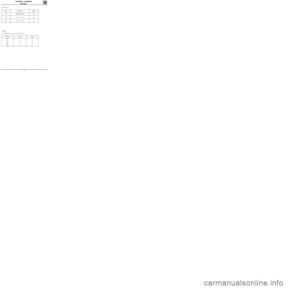
ENGINE ALTERNATOR CURRENT
D7F DELPHI 104 802 215 80 A
E7J
VALEO A 11 VI 8775 A
F8Q
VALEO A 11 VI 8875 A
Engine rpm 75 amps 80 amps
1000
2000
3000
400046
68
71
7254
75
80
82
16-1
Trending: fuel filter, steering, fuel consumption, transmission oil, air conditioning, transmission, fuel pump


