SSANGYONG KORANDO 1997 Service Repair Manual
KORANDO 1997
SSANGYONG
SSANGYONG
https://www.carmanualsonline.info/img/67/57502/w960_57502-0.png
SSANGYONG KORANDO 1997 Service Repair Manual
Trending: service indicator, jacking, tire pressure, fuse chart, seat memory, tow bar, radio
Page 311 of 2053
1B2 -- 18 M161 ENGINE MECHANICAL
D AEW OO M Y_2000
GENERATOR
1 Bolt (M8 X 40, 3 pieces)
22.5-- 27.5 NSm (16.6-- 20.3 lb-ft) .............
2 Bolt (M8 X 70, 2 pieces)
22.5-- 27.5 NSm (16.6-- 20.3 lb-ft) .............3 Bolt (M8 X 85, 1 piece)
22.5-- 27.5 NSm (16.6--20.3 lb-ft) .............
4 Generator Bracket
Removal & Installation Procedure
1. Disconnect the negative battery cable.
2. Remove the drive belt.
3. Remove the generator.
4. Unscrew the generator carrier bolts and remove the
carrier.
Installation Notice
Tightening Torque
25 NSm (18 lb-ft)
Notice:Apply 3 Nm of torque when mounting the bolt
(1) ; apply 25 Nm of torque when mounting the bolts (2),
and (3) ; and then tighten the bolt (1) with 25 Nm of
torque.
5. Installation should follow the removal procedure in
the reverse order.
Page 312 of 2053
M161 ENGINE MECHANICAL 1B2 -- 19
D AEW OO M Y_2000
ENGINE MOUNT
Removal & Installation Procedure
1. Unscrew the upper engine mount nuts and remove
the engine.
Installation Notice
Tightening Torque
70 NSm (52 lb-ft)
2. Unscrew the lower nuts.
Installation Notice
Tightening Torque
38 NSm (28 lb-ft)
3. Remove the hydraulic engine mounting insulator.
4. Installation should follow the removal procedure in
the reverse order.
Page 313 of 2053
1B2 -- 20 M161 ENGINE MECHANICAL
D AEW OO M Y_2000
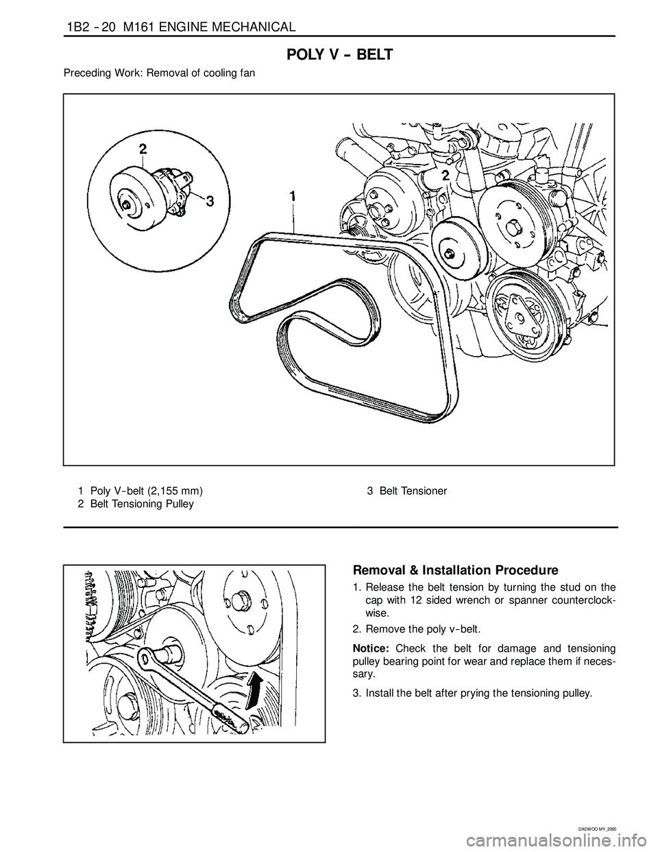
POLY V -- BELT
Preceding Work: Removal of cooling fan
1 Poly V-- belt (2,155 mm)
2 Belt Tensioning Pulley3 Belt Tensioner
Removal & Installation Procedure
1. Release the belt tension by turning the stud on the
cap with 12 sided wrench or spanner counterclock-
wise.
2. Remove the poly v -- belt.
Notice:Check the belt for damage and tensioning
pulley bearing point for wear and replace them if neces-
sary.
3. Install the belt after prying the tensioning pulley.
Page 314 of 2053
1B2 -- 22 M161 ENGINE MECHANICAL
D AEW OO M Y_2000
TENSIONING DEVICE
Preceding Work: Removal of tensioning device shock absorber
1 Bolt (M8 x 75, 2 pieces) +
Washer 22.5-- 27.5 NSm (16.6-- 20.3 lb-ft) ......
2 Bolt (M8 x 25, 1 pieces) +
Washer 22.5-- 27.5 NSm (16.6-- 20.3 lb-ft) ......3 Tensioning Device
4 Stud bolt
5 Tensioning Arm
Removal & Installation Procedure
1. Turn the stud bolt to counterclockwise.
2. Insert the pin (111 589 01 15 00) into the hole in ten-
sioning arm.
3. Unscrew the bolts (1, 2) and remove the tensioning
device.
Installation Notice
Tightening Torque
22.5 -- 27.5 NSm
(16.6 -- 20.3 lb-ft)
4. Installation should follow the removal procedure in
the reverse order.
Page 315 of 2053
M161 ENGINE MECHANICAL 1B2 -- 21
D AEW OO M Y_2000
Poly V - Belt Arrangement
1 Belt Tensioning Pulley
2 Crankshaft Belt Pulley
3 A/C Compressor Pulley5 Generator Pulley
7 Power Steering Pump Pulley
8 Water Pump Pulley
Page 316 of 2053
M161 ENGINE MECHANICAL 1B2 -- 23
D AEW OO M Y_2000
TENSIONING DEVICE SHOCK ABSORBER
1 End Cover
2 Bolt 40.5-- 49.5 NSm (29.9-- 36.5 lb-ft) .........
3 Tensioning Pulley
4 Bolt (M8 X 25) + Washer
22.5-- 27.5 NSm (16.6-- 20.3 lb-ft) .............5 Tensioning Device
6 Bolt (M8 X 35) + Washer
22.5-- 27.5 NSm (16.6--20.3 lb-ft) .............
7 Shock Absorber
Removal & Installation Procedure
1. Remove the end cover (1).
2. Remove the bolt (2) and remove the tensioning pulley
(3).
Installation Notice
Tightening Torque
40.5 -- 49.5 NSm
(29.9 -- 36.5 lb-ft)
3. Unscrew the bolts (4,6) and remove the shock ab-
sorber (7).
Installation Notice
Tightening Torque
22.5 -- 27.5 NSm
(16.6 -- 20.3 lb-ft)
Page 317 of 2053
1B2 -- 24 M161 ENGINE MECHANICAL
D AEW OO M Y_2000
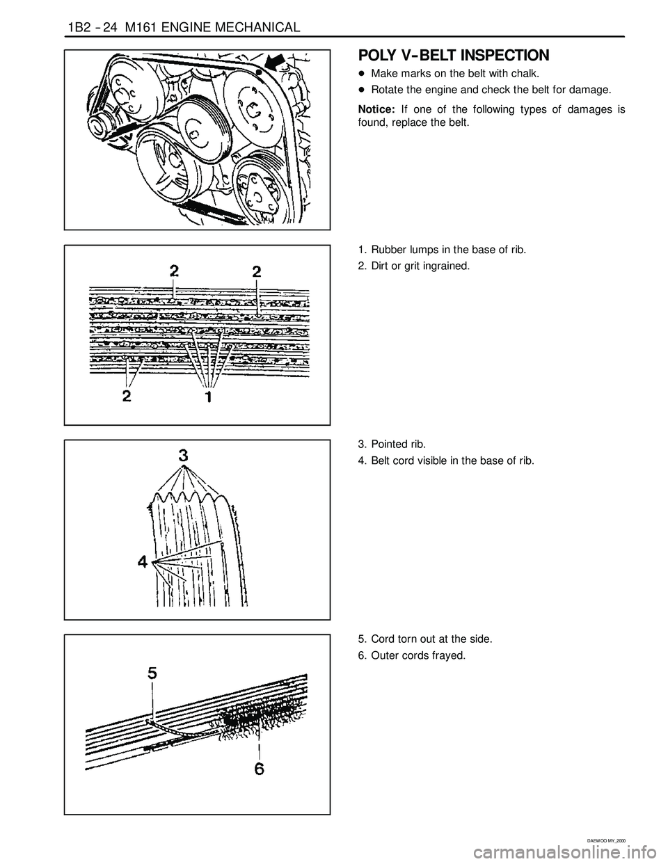
POLY V-- BELT INSPECTION
DMake marks on the belt with chalk.
DRotate the engine and check the belt for damage.
Notice:If one of the following types of damages is
found, replace the belt.
1. Rubber lumps in the base of rib.
2. Dirt or grit ingrained.
3. Pointed rib.
4. Belt cord visible in the base of rib.
5. Cord torn out at the side.
6. Outer cords frayed.
Page 318 of 2053
M161 ENGINE MECHANICAL 1B2 -- 25
D AEW OO M Y_2000
7. Rib detached from the base of belt.
8. Splits across the rib.
9. Sections of rib torn out.
10. Splits across several ribs.
11. Splits across the back of the belt.
Page 319 of 2053
1B2 -- 26 M161 ENGINE MECHANICAL
D AEW OO M Y_2000
CYLINDER HEAD COVER
1 Spark Plug Cover
2 Spark Plug Connector
3 Bolt(M6X45:4pieces,M6X60:6pieces)
9--11 NSm (80-- 97 lb-in) .....................4 Cylinder Head Cover
5 Gasket Replace...........................
Page 320 of 2053
M161 ENGINE MECHANICAL 1B2 -- 27
D AEW OO M Y_2000
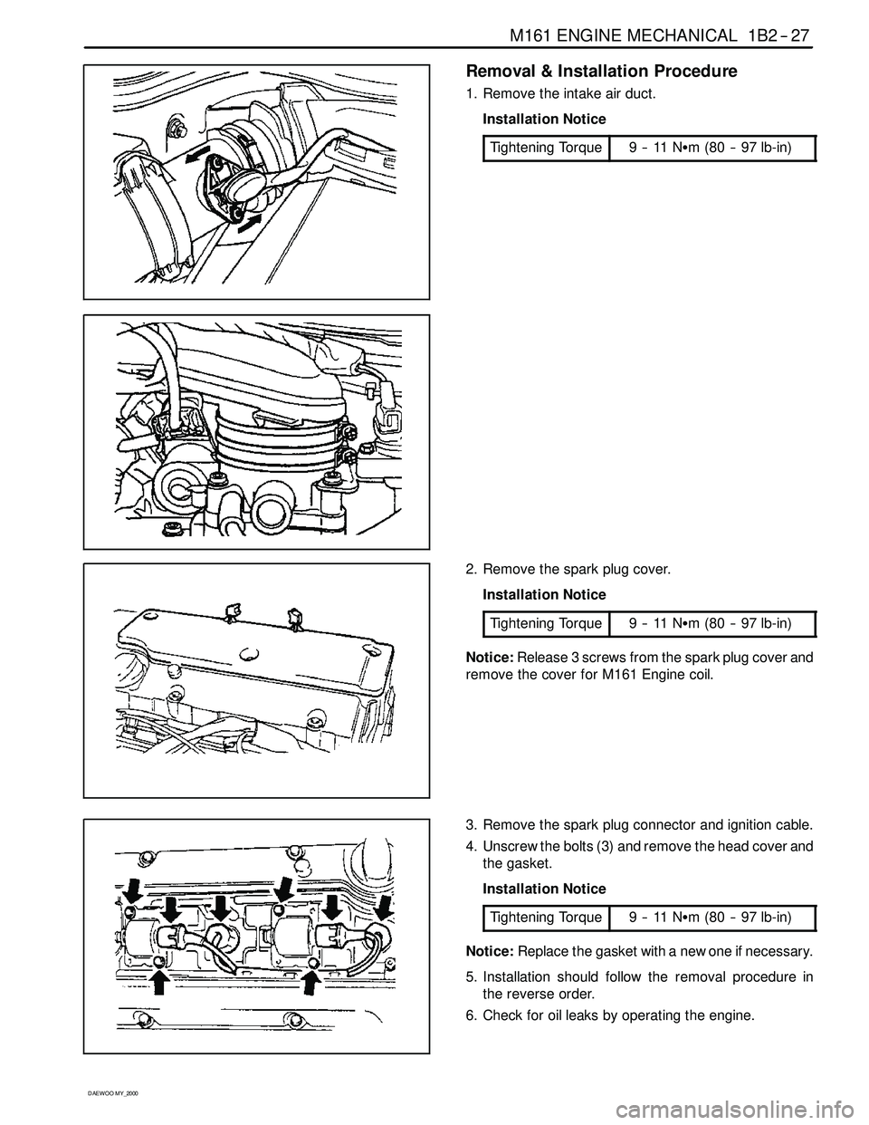
Removal & Installation Procedure
1. Remove the intake air duct.
Installation Notice
Tightening Torque
9--11NSm (80 -- 97 lb-in)
2. Remove the spark plug cover.
Installation Notice
Tightening Torque
9--11NSm (80 -- 97 lb-in)
Notice:Release 3 screws from the spark plug cover and
remove the cover for M161 Engine coil.
3. Remove the spark plug connector and ignition cable.
4. Unscrew the bolts (3) and remove the head cover and
the gasket.
Installation Notice
Tightening Torque
9--11NSm (80 -- 97 lb-in)
Notice:Replace the gasket with a new one if necessary.
5. Installation should follow the removal procedure in
the reverse order.
6. Check for oil leaks by operating the engine.
Trending: tow bar, battery, cabi, boot, STARTER MOTOR, height adjustment, key


