SUZUKI SWIFT 2000 1.G Transmission Service Workshop Manual
Manufacturer: SUZUKI, Model Year: 2000, Model line: SWIFT, Model: SUZUKI SWIFT 2000 1.GPages: 447, PDF Size: 10.54 MB
Page 321 of 447

BODY SERVICE 9-17
QUARTER WINDOW
REMOVAL AND INSTALLATION
Refer to “WINDSHIELD” in this section as removal and installa-
tion procedures are basically the same. However, note the follow-
ing.
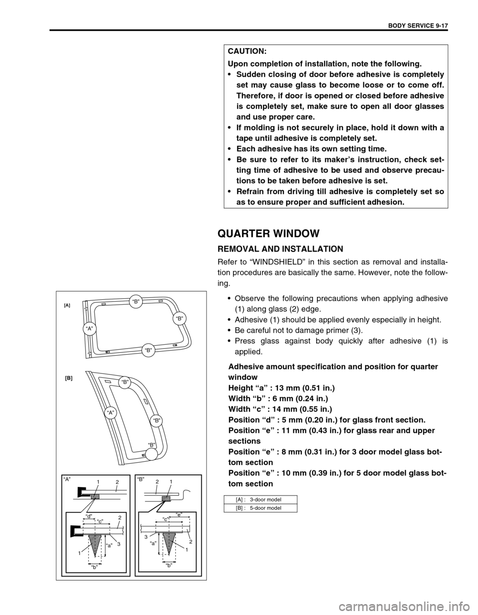
Observe the following precautions when applying adhesive
(1) along glass (2) edge.
Adhesive (1) should be applied evenly especially in height.
Be careful not to damage primer (3).
Press glass against body quickly after adhesive (1) is
applied.
Adhesive amount specification and position for quarter
window
Height “a” : 13 mm (0.51 in.)
Width “b” : 6 mm (0.24 in.)
Width “c” : 14 mm (0.55 in.)
Position “d” : 5 mm (0.20 in.) for glass front section.
Position “e” : 11 mm (0.43 in.) for glass rear and upper
sections
Position “e” : 8 mm (0.31 in.) for 3 door model glass bot-
tom section
Position “e” : 10 mm (0.39 in.) for 5 door model glass bot-
tom section CAUTION:
Upon completion of installation, note the following.
Sudden closing of door before adhesive is completely
set may cause glass to become loose or to come off.
Therefore, if door is opened or closed before adhesive
is completely set, make sure to open all door glasses
and use proper care.
If molding is not securely in place, hold it down with a
tape until adhesive is completely set.
Each adhesive has its own setting time.
Be sure to refer to its maker’s instruction, check set-
ting time of adhesive to be used and observe precau-
tions to be taken before adhesive is set.
Refrain from driving till adhesive is completely set so
as to ensure proper and sufficient adhesion.
[A] : 3-door model
[B] : 5-door model
“A”
“A”“B”
“B”
“B”
“B”
“B”“B”
11
22
2
33 “d”
“c”“c”“e”
“a”“a”
“b”“b”
11
2 “A”“B”
[A]
[B]
Page 322 of 447

9-18 BODY SERVICE
BACK DOOR GLASS
REMOVAL AND INSTALLATION
Refer to “WINDSHIELD” in this section as removal and installa-
tion procedures are basically the same. However, note the follow-
ing.
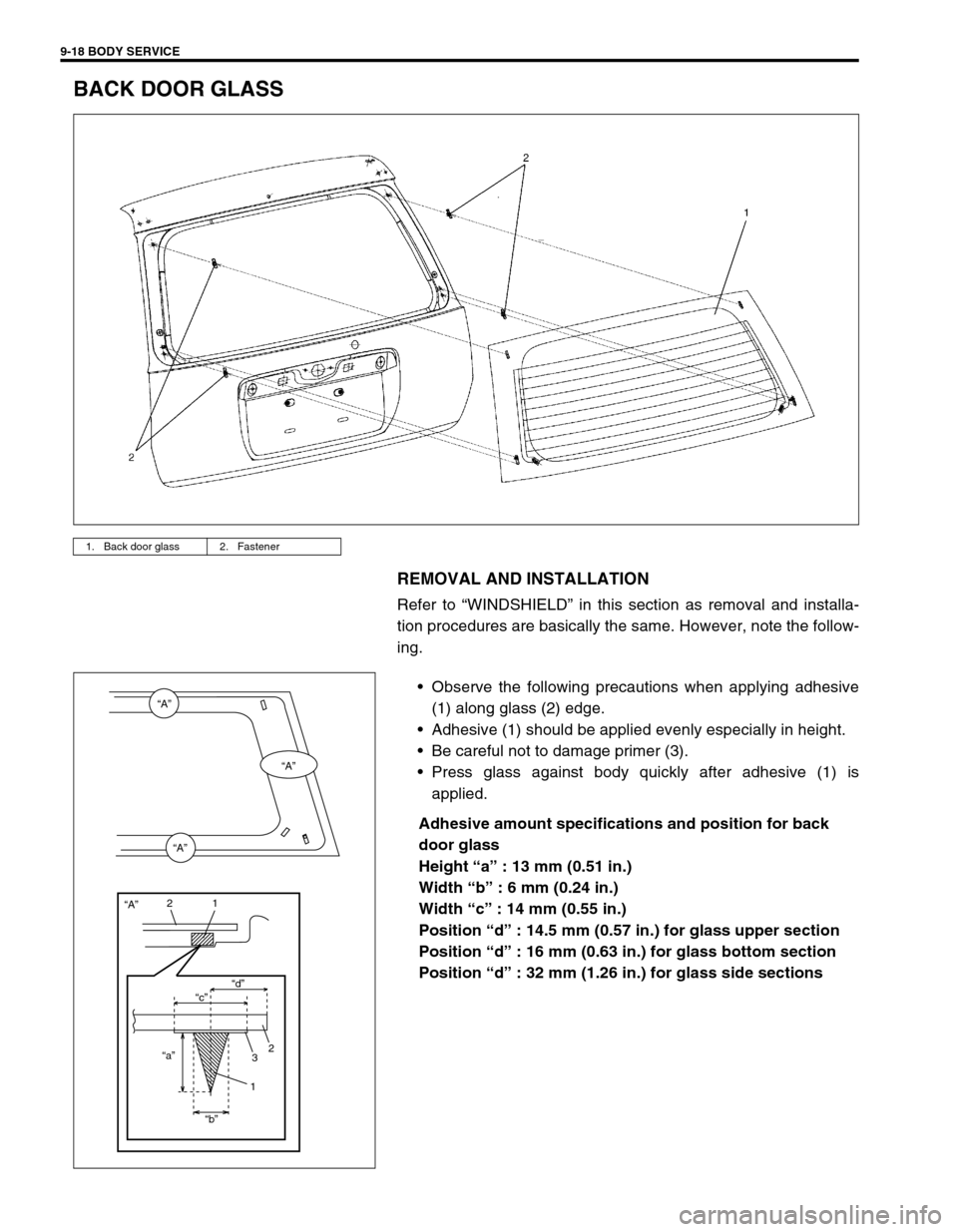
Observe the following precautions when applying adhesive
(1) along glass (2) edge.
Adhesive (1) should be applied evenly especially in height.
Be careful not to damage primer (3).
Press glass against body quickly after adhesive (1) is
applied.
Adhesive amount specifications and position for back
door glass
Height “a” : 13 mm (0.51 in.)
Width “b” : 6 mm (0.24 in.)
Width “c” : 14 mm (0.55 in.)
Position “d” : 14.5 mm (0.57 in.) for glass upper section
Position “d” : 16 mm (0.63 in.) for glass bottom section
Position “d” : 32 mm (1.26 in.) for glass side sections
1. Back door glass 2. Fastener
“A”
“A”
“A”
“A”
“c”“d”
“a”
“b”
21
2
3
1
Page 323 of 447

BODY SERVICE 9-19
BODY STRUCTURE
FRONT DOOR ASSEMBLY
REMOVAL
1) Remove front fender.
2) Disconnect door harness lead wires at each coupler, if
equipped.
3) Remove stopper pin (1) from door open stopper (2).
1. Door panel 5. Door hinge washer
: Not necessary to install
2. Door hinge
: Apply lithium grease 99000-25010 to rotating part
: Apply sealant 99000-31110 to contact face6. Front door hinge bolt
3. Door stopper pin Tightening torque
4. Door open stopper Do not reuse.
Page 324 of 447

9-20 BODY SERVICE
4) Support door panel (1) using a jack (2) with a piece of wood
placed (4) between jack (2) and panel (1) as shown.
5) Remove door assembly (1) by loosening hinge mounting
bolts (2).
INSTALLATION
Reverse removal procedure to install door assembly noting the
following instructions.
When replacing door, coat replacement door inside with wax
for proper anti-corrosion treatment.
Refer to “ANTI-CORROSION COMPOUND APPLICATION
AREA” in this section.
Apply sealant to contact face “A” of hinge (1) and apply
grease to rotating part “B” of hinge (1).
“A” : Sealant 99000-31110
“B” : Lithium grease 99000-25010
Tighten hinge bolt (1) to specified torque.
Tightening torque
Door hinge mounting bolt
(a) : 23 N·m (2.3 kg-m, 17.0 lb-ft)
3. Rags
1, (a)
1, (a)
1, (a)
Page 325 of 447

BODY SERVICE 9-21
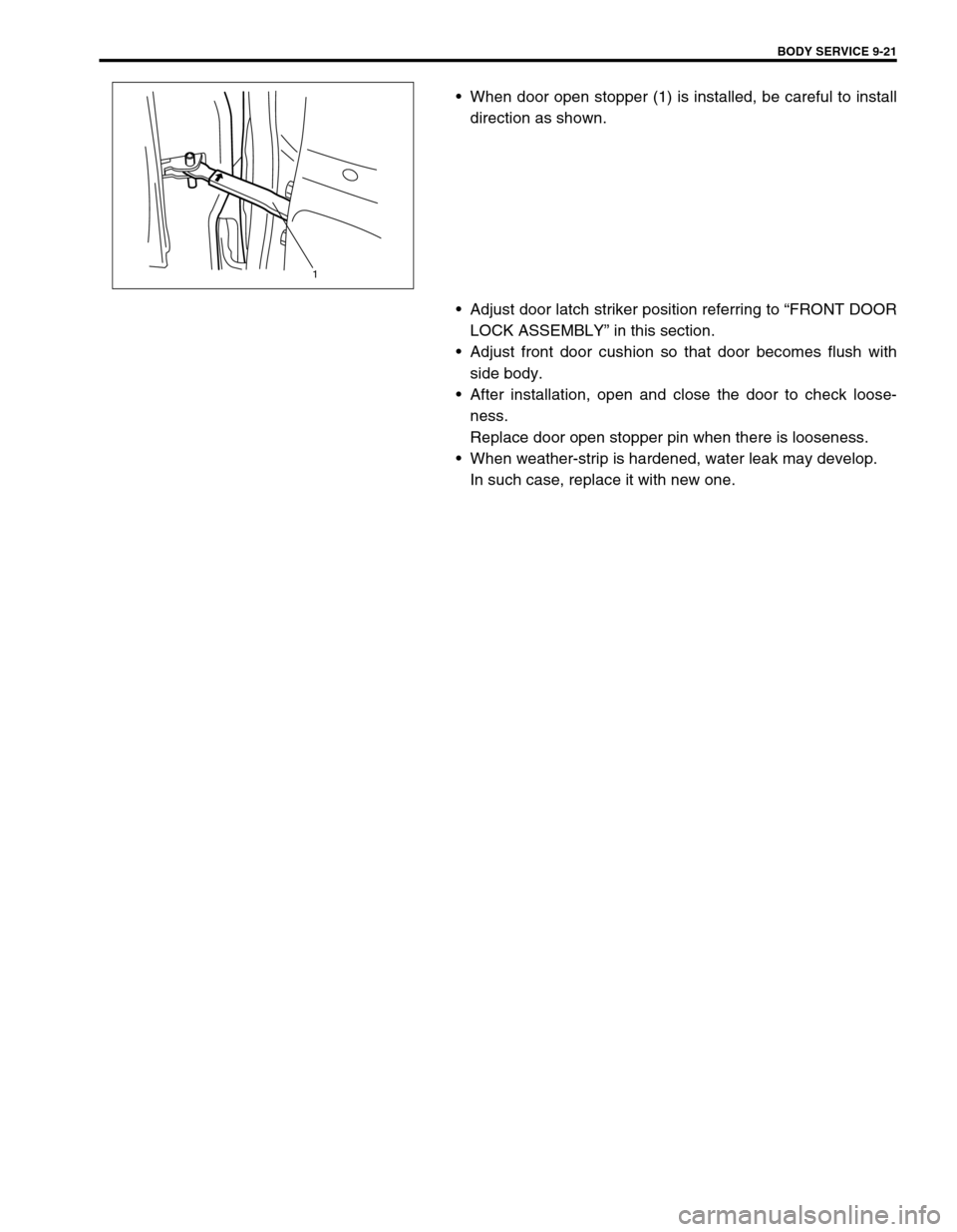
When door open stopper (1) is installed, be careful to install
direction as shown.
Adjust door latch striker position referring to “FRONT DOOR
LOCK ASSEMBLY” in this section.
Adjust front door cushion so that door becomes flush with
side body.
After installation, open and close the door to check loose-
ness.
Replace door open stopper pin when there is looseness.
When weather-strip is hardened, water leak may develop.
In such case, replace it with new one.
1
Page 326 of 447

9-22 BODY SERVICE
REAR DOOR ASSEMBLY
REMOVAL AND INSTALLATION
Refer to “FRONT DOOR ASSEMBLY” in this section noting the
following instructions.
Refer to above figure for tightening torque, grease and seal-
ant.
When door open stopper is installed, be careful to face side.
Door stopper installing direction
Right side door : RR punch mark is upward.
Left side door : RL punch mark is upward.
1. Door panel 4. Door stopper Do not reuse.
2. Door hinge
: Apply lithium grease 99000-25010 to rotating part
: Apply sealant 99000-31110 to contact face5. Rear door hinge bolt
3. Door stopper pin Tightening torque
Page 327 of 447

BODY SERVICE 9-23
BACK DOOR ASSEMBLY
REMOVAL
1) Remove back door trim (1).
2) Remove related section of head lining and quarter trim.
3) Disconnect back door harness connectors (2) and washer
hose (3).
4) Remove wire harness connectors inside back door.
5) Remove back door balancer (4) (first at its door side and next
at its body side).
6) Remove door hinge nuts (5) and remove back door assembly
(6).
1. Back door panel assembly 4. Back door balancer unit
2. Back door window glass 5. Back door trim
3. Back door hinge
: Apply lithium grease 99000-25010 to door hinge moving section
: Apply sealant 99000-31110 to contact face6. Weather strip
Page 328 of 447

9-24 BODY SERVICE
INSTALLATION
Reverse removal procedure to install back door noting the follow-
ing instructions.
Secure wiring harness.
Adjust door latch striker position by referring “BACK DOOR
LOCK ASSEMBLY” in this section.
Adjust door cushion so that door contacts body when closed.
Adjust door clearance by loosening door hinge mounting
bolts and nuts referring to “PANEL CLEARANCE” in this sec-
tion.
Apply sealant to contact face “A” of door hinge (1) and apply
grease to rotating part “B” of hinge (1).
“A” : Sealant 99000-31110
“B” : Lithium grease 99000-25010 WARNING:
Handling of Back Door Balancer (Damper)
Do not disassemble balancer (1) because its cylinder is
filled with gas.
Handle balancer carefully. Do not scar or scratch
exposed surface of its piston rod, and never allow any
paint or oil to stick to its surface.
Do not turn piston rod with balancer fully extended.
When discarding removed back door balancer
(damper), use a 2 – 3 mm (0.08 – 0.12 in.) drill (2) to
make a hole as shown.
The gas itself is harmless but it may issue out of the
hole together with chips generated by the drill (2).
Therefore, be sure to wear goggle.
Page 329 of 447

BODY SERVICE 9-25
HOOD
REMOVAL
1) Remove window washer hose (1) from hood (2).
2) Remove 4 mounting bolts (3) to detach hood (2).
INSTALLATION
Reverse removal procedure to install hood noting the following
instruction.
Apply sealant to contact face “B” of hood hinge (4).
“B” : Sealant 99000-3110
ADJUSTMENT
Adjust the following point :
Hood position adjustment.
Fore-and-aft and right-and-left adjustment.
Adjust hood clearance by loosening hood mounting bolts,
refer to “PANEL CLEARANCE” in this section.
Vertical adjustment
If only one side (right or left) of hood is not level with front
fender, make it level by tightening or loosening hood cushion
(1).
Hood lock position adjustment
When installing hood lock (1), bring bolt at highest position
and move it in vertical direction for adjustment free from
loose to hood striker.
Tightening torque
Hood latch bolts (a) : 10 N·m (1.0 kg-m, 7.0 lb-ft) CAUTION:
Place cloth on “A” in figure to prevent from any damage.
33
4
“B”
“B”
1 2
“A”“A”
Page 330 of 447

9-26 BODY SERVICE
INSPECTION
Check that hood opens and closes smoothly and properly. Lubri-
cate if necessary. Also check that secondary latch operates prop-
erly (check that secondary latch keeps hood from opening all the
way) and hood locks securely when closed.
Adjust hood locks position if necessary.
FRONT FENDER
REMOVAL
1) Remove front fender side moulding.
2) Remove front bumper.
3) Disconnect connector of side turn signal (or side marker)
lamp.
4) Remove front fender lining.
5) Remove front fender.
INSTALLATION
Reverse removal procedure to install front fender noting the fol-
lowing instructions.
If paint on fender bolt is peeled off, be sure to apply paint
again.
Adjust panel clearance referring to “PANEL CLEARANCE” in
this section.
1. Front fender lining 2. Front fender 3. Front fender side moulding
“A”“A”
2
3
1
“A”