TOYOTA RAV4 2006 Service Repair Manual
Manufacturer: TOYOTA, Model Year: 2006, Model line: RAV4, Model: TOYOTA RAV4 2006Pages: 2000, PDF Size: 45.84 MB
Page 551 of 2000

2GR-FE ENGINE CONTROL SYSTEM – SFI SYSTEMES–27
ES
READINESS MONITOR DRIVE
PAT T E R N
1. PURPOSE OF READINESS TESTS
• The On-Board Diagnostic (OBD II) system is designed to
monitor the performance of emission related components,
and indicate any detected abnormalities with DTC
(Diagnostic Trouble Codes). Since various components
need to be monitored during different driving conditions,
the OBD II system is designed to run separate monitoring
programs called Readiness Monitors.
• The intelligent tester's software must be version 9.0 or
newer to view the Readiness Monitor Status. To view the
status, select the following menu items: DIAGNOSIS /
ENHANCED OBD II / MONITOR INFO / MONITOR
STATUS.
• When the Readiness Monitor status reads COMPL
(complete), the necessary conditions have been met for
running the performance tests for that Readiness Monitor.
• A generic OBD II scan tool can also be used to view the
Readiness Monitor status.
HINT:
Many state Inspection and Maintenance (I/M) programs
require a vehicle's Readiness Monitor status to show COMPL
before beginning emission tests.
The Readiness Monitor will be reset to INCMPL (incomplete)
if:
• The ECM has lost battery power or blown a fuse.
• DTCs have been cleared.
• The conditions for running the Readiness Monitor have not
been met.
If the Readiness Monitor status shows INCMPL, follow the
appropriate Readiness Monitor Drive Pattern to change the
status to COMPL.
CAUTION:
Strictly observe posted speed limits, traffic laws, and
road conditions when performing these drive patterns.
NOTICE:
These drive patterns represent the fastest method of
satisfying all conditions necessary to achieve complete
status for each specific Readiness Monitor.
In the event of a drive pattern being interrupted (possibly
due to factors such as traffic conditions), the drive
pattern can be resumed. In most cases, the Readiness
Monitor will still achieve complete status upon
completion of the drive pattern.
To ensure completion of the Readiness Monitors, avoid
sudden changes in vehicle load and speed (driving up
and down hills and/or sudden acceleration).
Page 552 of 2000
ES–282GR-FE ENGINE CONTROL SYSTEM – SFI SYSTEM
ES
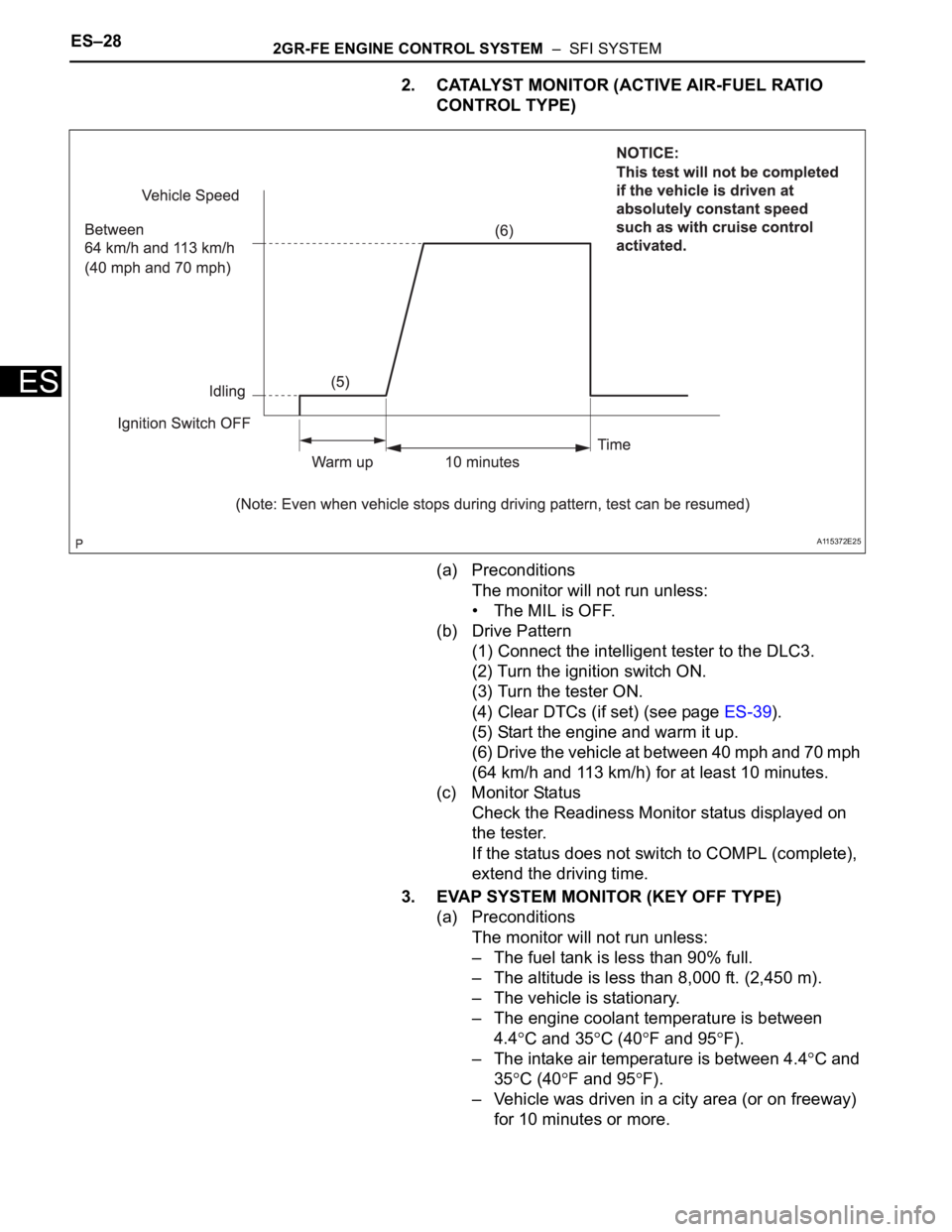
2. CATALYST MONITOR (ACTIVE AIR-FUEL RATIO
CONTROL TYPE)
(a) Preconditions
The monitor will not run unless:
• The MIL is OFF.
(b) Drive Pattern
(1) Connect the intelligent tester to the DLC3.
(2) Turn the ignition switch ON.
(3) Turn the tester ON.
(4) Clear DTCs (if set) (see page ES-39).
(5) Start the engine and warm it up.
(6) Drive the vehicle at between 40 mph and 70 mph
(64 km/h and 113 km/h) for at least 10 minutes.
(c) Monitor Status
Check the Readiness Monitor status displayed on
the tester.
If the status does not switch to COMPL (complete),
extend the driving time.
3. EVAP SYSTEM MONITOR (KEY OFF TYPE)
(a) Preconditions
The monitor will not run unless:
– The fuel tank is less than 90% full.
– The altitude is less than 8,000 ft. (2,450 m).
– The vehicle is stationary.
– The engine coolant temperature is between
4.4
C and 35C (40F and 95F).
– The intake air temperature is between 4.4
C and
35
C (40F and 95F).
– Vehicle was driven in a city area (or on freeway)
for 10 minutes or more.
A115372E25
Page 553 of 2000
2GR-FE ENGINE CONTROL SYSTEM – SFI SYSTEMES–29
ES
(b) Monitor Conditions
(1) Turn the ignition switch OFF and wait for 6
hours.
HINT:
Do not start the engine until checking Readiness
Monitor status. If the engine is started, the step
described above must be repeated.
(c) Monitor Status
(1) Connect the intelligent tester to the DLC3.
(2) Turn the ignition switch ON.
(3) Turn the tester ON.
(4) Check the Readiness Monitor status displayed
on the tester.
If the status does not switch to COMPL (complete), restart the
engine, make sure that the preconditions have been met, and
then perform the Monitor Conditions again.
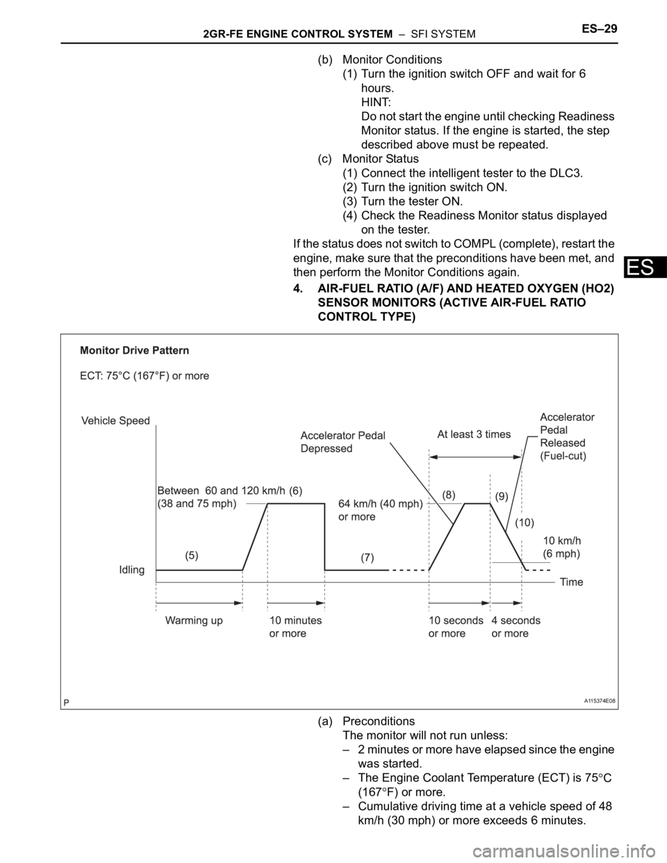
4. AIR-FUEL RATIO (A/F) AND HEATED OXYGEN (HO2)
SENSOR MONITORS (ACTIVE AIR-FUEL RATIO
CONTROL TYPE)
(a) Preconditions
The monitor will not run unless:
– 2 minutes or more have elapsed since the engine
was started.
– The Engine Coolant Temperature (ECT) is 75
C
(167
F) or more.
– Cumulative driving time at a vehicle speed of 48
km/h (30 mph) or more exceeds 6 minutes.
A115374E08
Page 554 of 2000
ES–302GR-FE ENGINE CONTROL SYSTEM – SFI SYSTEM
ES
– Air-fuel ratio feedback control is performed.
(b) Drive Pattern for front A/F sensor and HO2 sensor
(1) Connect the intelligent tester to the DLC3.
(2) Turn the ignition switch ON.
(3) Turn the tester ON.
(4) Clear DTCs (see page ES-39).
(5) Start the engine, and warm it up until the ECT
reaches 75
C (167F) or higher.
(6) Drive the vehicle at between 60 km/h (38 mph)
and 120 km/h (75 mph) for at least 10 minutes.
(7) Change the transmission to 2nd gear.
(8) Accelerate the vehicle to 64 km/h (40 mph) or
more by depressing the accelerator pedal for at
least 10 seconds.
(9) Soon after performing step (8) above, release
the accelerator pedal for at least 4 seconds without
depressing the brake pedal in order to execute fuel-
cut control.
(10) Allow the vehicle to decelerate until the vehicle
speed declines to less than 10 km/h (6 mph).
(11) Repeat steps from (8) through (10) above at
least 3 times in one driving cycle.
(c) Monitor Status
(1) Check the Readiness Monitor status displayed
on the tester.
(2) If the status does not switch to COMPL
(complete), make sure that the preconditions
have been met, and then perform steps from (5)
through (11) in the Drive Pattern above.
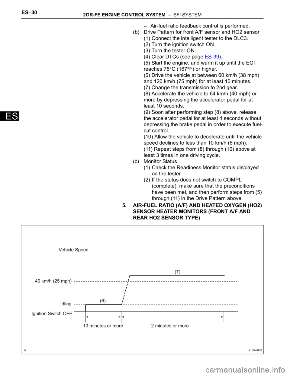
5. AIR-FUEL RATIO (A/F) AND HEATED OXYGEN (HO2)
SENSOR HEATER MONITORS (FRONT A/F AND
REAR HO2 SENSOR TYPE)
A121604E06
Page 555 of 2000

2GR-FE ENGINE CONTROL SYSTEM – SFI SYSTEMES–31
ES
(a) Preconditions
The monitor will not run unless:
– The MIL is OFF.
(b) Drive Pattern
(1) Connect the intelligent tester to the DLC3.
(2) Turn the ignition switch ON.
(3) Turn the tester ON.
(4) Clear DTCs (if set) (see page ES-39).
(5) Start the engine.
(6) Allow the engine to idle for 10 minutes or more.
(7) Drive the vehicle at 40 km/h (25 mph) or more
for at least 2 minutes.
(c) Monitor Status
(1) Check the Readiness Monitor status displayed
on the tester.
If the status does not switch to COMPL
(complete), make sure that the preconditions
have been met, and repeat steps from (5) to (7)
described in the Drive Pattern above.
Page 556 of 2000
ES–322GR-FE ENGINE CONTROL SYSTEM – SFI SYSTEM
ES
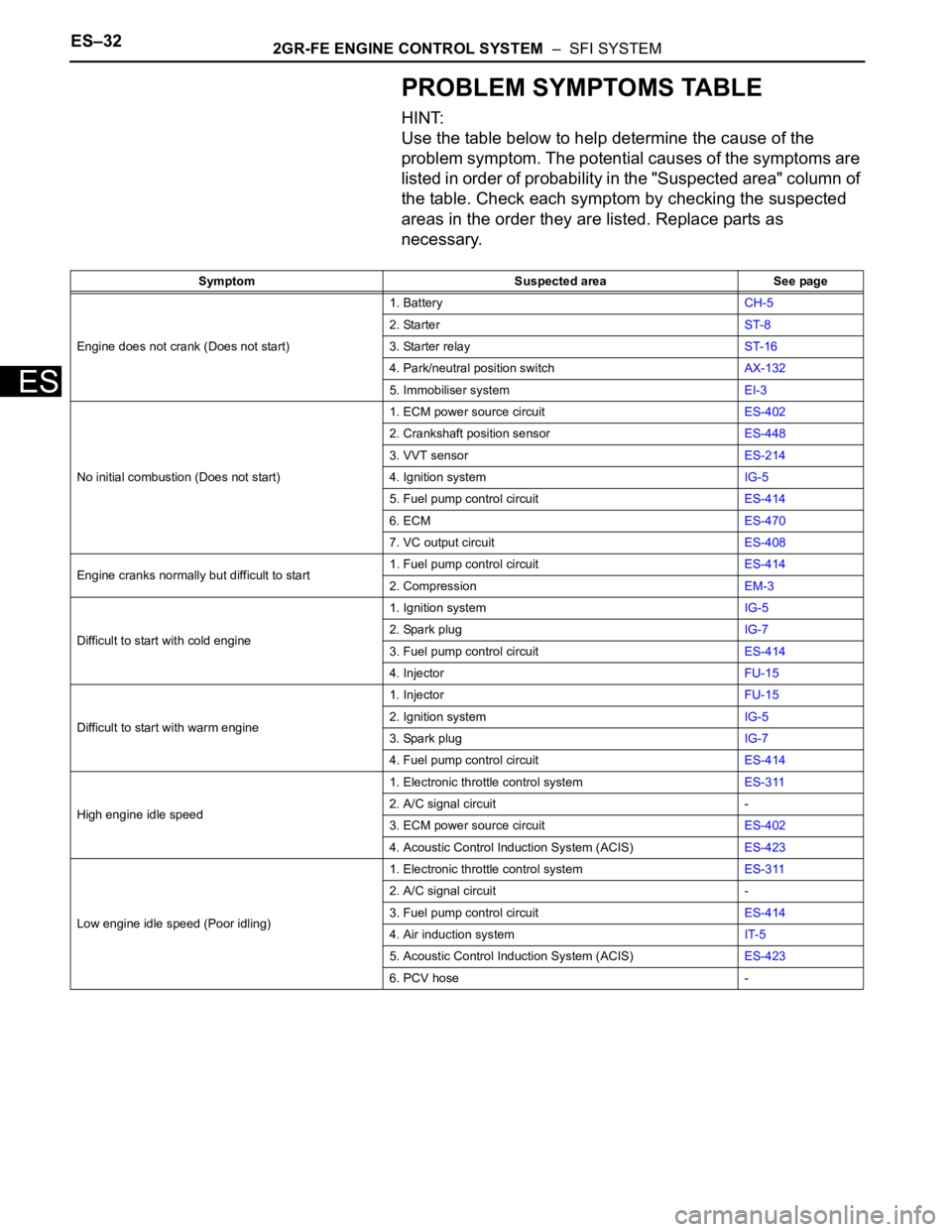
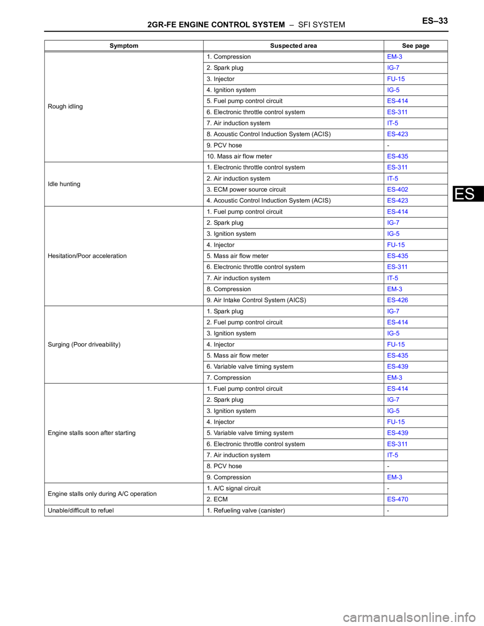
PROBLEM SYMPTOMS TABLE
HINT:
Use the table below to help determine the cause of the
problem symptom. The potential causes of the symptoms are
listed in order of probability in the "Suspected area" column of
the table. Check each symptom by checking the suspected
areas in the order they are listed. Replace parts as
necessary.
Symptom Suspected area See page
Engine does not crank (Does not start)1. BatteryCH-5
2. StarterST-8
3. Starter relayST-16
4. Park/neutral position switchAX-132
5. Immobiliser systemEI-3
No initial combustion (Does not start)1. ECM power source circuitES-402
2. Crankshaft position sensorES-448
3. VVT sensorES-214
4. Ignition systemIG-5
5. Fuel pump control circuitES-414
6. ECMES-470
7. VC output circuitES-408
Engine cranks normally but difficult to start1. Fuel pump control circuitES-414
2. CompressionEM-3
Difficult to start with cold engine1. Ignition systemIG-5
2. Spark plugIG-7
3. Fuel pump control circuitES-414
4. InjectorFU-15
Difficult to start with warm engine1. InjectorFU-15
2. Ignition systemIG-5
3. Spark plugIG-7
4. Fuel pump control circuitES-414
High engine idle speed1. Electronic throttle control systemES-311
2. A/C signal circuit -
3. ECM power source circuitES-402
4. Acoustic Control Induction System (ACIS)ES-423
Low engine idle speed (Poor idling)1. Electronic throttle control systemES-311
2. A/C signal circuit -
3. Fuel pump control circuitES-414
4. Air induction systemIT-5
5. Acoustic Control Induction System (ACIS)ES-423
6. PCV hose -
Page 557 of 2000
2GR-FE ENGINE CONTROL SYSTEM – SFI SYSTEMES–33
ES
Rough idling1. CompressionEM-3
2. Spark plugIG-7
3. InjectorFU-15
4. Ignition systemIG-5
5. Fuel pump control circuitES-414
6. Electronic throttle control systemES-311
7. Air induction systemIT-5
8. Acoustic Control Induction System (ACIS)ES-423
9. PCV hose -
10. Mass air flow meterES-435
Idle hunting1. Electronic throttle control systemES-311
2. Air induction systemIT-5
3. ECM power source circuitES-402
4. Acoustic Control Induction System (ACIS)ES-423
Hesitation/Poor acceleration1. Fuel pump control circuitES-414
2. Spark plugIG-7
3. Ignition systemIG-5
4. InjectorFU-15
5. Mass air flow meterES-435
6. Electronic throttle control systemES-311
7. Air induction systemIT-5
8. CompressionEM-3
9. Air Intake Control System (AICS)ES-426
Surging (Poor driveability)1. Spark plugIG-7
2. Fuel pump control circuitES-414
3. Ignition systemIG-5
4. InjectorFU-15
5. Mass air flow meterES-435
6. Variable valve timing systemES-439
7. CompressionEM-3
Engine stalls soon after starting1. Fuel pump control circuitES-414
2. Spark plugIG-7
3. Ignition systemIG-5
4. InjectorFU-15
5. Variable valve timing systemES-439
6. Electronic throttle control systemES-311
7. Air induction systemIT-5
8. PCV hose -
9. CompressionEM-3
Engine stalls only during A/C operation1. A/C signal circuit -
2. ECMES-470
Unable/difficult to refuel 1. Refueling valve (canister) -Symptom Suspected area See page
Page 558 of 2000
ES–342GR-FE ENGINE CONTROL SYSTEM – SFI SYSTEM
ES
TERMINALS OF ECM
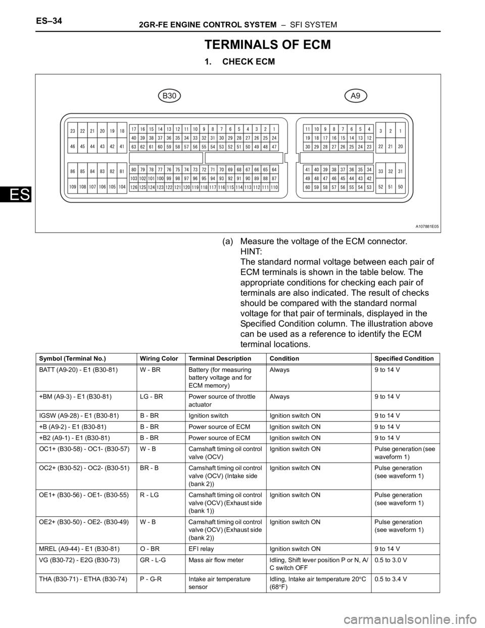
1. CHECK ECM
(a) Measure the voltage of the ECM connector.
HINT:
The standard normal voltage between each pair of
ECM terminals is shown in the table below. The
appropriate conditions for checking each pair of
terminals are also indicated. The result of checks
should be compared with the standard normal
voltage for that pair of terminals, displayed in the
Specified Condition column. The illustration above
can be used as a reference to identify the ECM
terminal locations.
A107881E05
Symbol (Terminal No.) Wiring Color Terminal Description Condition Specified Condition
BATT (A9-20) - E1 (B30-81) W - BR Battery (for measuring
battery voltage and for
ECM memory)Always 9 to 14 V
+BM (A9-3) - E1 (B30-81) LG - BR Power source of throttle
actuatorAlways 9 to 14 V
IGSW (A9-28) - E1 (B30-81) B - BR Ignition switch Ignition switch ON 9 to 14 V
+B (A9-2) - E1 (B30-81) B - BR Power source of ECM Ignition switch ON 9 to 14 V
+B2 (A9-1) - E1 (B30-81) B - BR Power source of ECM Ignition switch ON 9 to 14 V
OC1+ (B30-58) - OC1- (B30-57) W - B Camshaft timing oil control
valve (OCV)Ignition switch ON Pulse generation (see
waveform 1)
OC2+ (B30-52) - OC2- (B30-51) BR - B Camshaft timing oil control
valve (OCV) (Intake side
(bank 2))Ignition switch ON Pulse generation
(see waveform 1)
OE1+ (B30-56) - OE1- (B30-55) R - LG Camshaft timing oil control
valve (OCV) (Exhaust side
(bank 1))Ignition switch ON Pulse generation
(see waveform 1)
OE2+ (B30-50) - OE2- (B30-49) W - B Camshaft timing oil control
valve (OCV) (Exhaust side
(bank 2))Ignition switch ON Pulse generation
(see waveform 1)
MREL (A9-44) - E1 (B30-81) O - BR EFI relay Ignition switch ON 9 to 14 V
VG (B30-72) - E2G (B30-73) GR - L-G Mass air flow meter Idling, Shift lever position P or N, A/
C switch OFF0.5 to 3.0 V
THA (B30-71) - ETHA (B30-74) P - G-R Intake air temperature
sensorIdling, Intake air temperature 20
C
(68F)0.5 to 3.4 V
Page 559 of 2000

2GR-FE ENGINE CONTROL SYSTEM – SFI SYSTEMES–35
ES
THW (B30-79) - ETHW (B30-78) L - BR Engine coolant
temperature sensorIdling, Engine coolant temperature
80
C (176F)0.2 to 1.0 V
VCTA (B30-96) - ETA (B30-97) B - W Power source of throttle
position sensor (specific
voltage)Ignition switch ON 4.5 to 5.5 V
VTA1 (B30-98) - ETA (B30-97) Y - W Throttle position sensor
(for engine control)Ignition switch ON,
Throttle valve fully closed0.5 to 1.1 V
Ignition switch ON,
Throttle valve fully open3.3 to 4.9 V
VTA2 (B30-99) - ETA (B30-97) GR - W Throttle position sensor
(for sensor malfunction
detection)Ignition switch ON,
Throttle valve fully closed2.1 to 3.1 V
Ignition switch ON,
Throttle valve fully open4.6 to 5.0 V
VPA (A9-55) - EPA (A9-59) W - Y Accelerator pedal position
sensor (for engine control)Ignition switch ON,
Accelerator pedal released0.5 to 1.1 V
Ignition switch ON,
Accelerator pedal fully depressed2.6 to 4.5 V
VPA2 (A9-56) - EPA2 (A9-60) R - O Accelerator pedal position
sensor (for sensor
malfunctioning detection)Ignition switch ON,
Accelerator pedal released1.2 to 2.0 V
Ignition switch ON,
Accelerator pedal fully depressed3.4 to 5.0 V
VCPA (A9-57) - EPA (A9-59) B - Y Power source of
accelerator pedal position
sensor (for VPA)Ignition switch ON 4.5 to 5.5 V
VCP2 (A9-58) - EPA2 (A9-60) L - O Power source of
accelerator pedal position
sensor (for VPA2)Ignition switch ON 4.5 to 5.5 V
HA1A (B30-86) - E04 (B30-23)
HA2A (B30-109) - E04 (B30-23) G - BR
B - BRA/F sensor heater Idling Below 3.0 V
Ignition switch ON 9 to 14 V
A1A+ (B30-93) - E1 (B30-81) W -BR A/F sensor Ignition switch ON 3.3 V*
A1A- (B30-116) - E1 (B30-81) BR - BR A/F sensor Ignition switch ON3.0 V*
A2A+ (B30-120) - E1 (B30-81) L - BR A/F sensor Ignition switch ON 3.3 V*
A2A- (B30-119) - E1 (B30-81) Y - BR A/F sensor Ignition switch ON 3.0 V*
HT1B (B30-48) - E03 (B30-104)
HT2B (B30-47) - E03 (B30-104)LG - BR
Y - BRHeated oxygen sensor
heaterIdling Below 3.0 V
Ignition switch ON 9 to 14 V
OX1B (B30-88) - EX1B (B30-65)
OX2B (B30-87) - EX2B- (B30-64)W - GR
B - B-WHeated oxygen sensor Engine speed maintained at 2,500
rpm for 2 minutes after warming up
sensorPulse generation (see
waveform 2)
#10 (B30-45) - E01 (B30-22)
#20 (B30-85) - E01 (B30-22)
#30 (B30-44) - E01 (B30-22)
#40 (B30-84) - E01 (B30-22)
#50 (B30-43) - E01 (B30-22)
#60 (B30-83) - E01 (B30-22)Y - BR
W - BR
B - BR
BR - BR
L - BR
G - BRInjector Ignition switch ON 9 to 14 V
Idling Pulse generation (see
waveform 3)
KNK1 (B30-95) - EKNK (B30-94)
KNK2 (B30-118) - EKN2 (B30-
11 7 )R - G
B - WKnock sensor Engine speed maintained at 4,000
rpm after warming up enginePulse generation (see
waveform 4)
VCV1 (B30-115) - E1 (B30-81) G-R - BR Power source for VVT
sensor (specific voltage)Ignition switch ON 4.5 to 5.0 V
VCV2 (B30-113) - E1 (B30-81) V - BR Power source for VVT
sensor (specific voltage)Ignition switch ON 4.5 to 5.0 V
VCE1 (B30-114) - E1 (B30-81) GR - BR Power source for VVT
sensor specific voltage)Ignition switch ON 4.5 to 5.0 V
VCE2 (B30-112) - E1 (B30-81) Y - BR Power source for VVT
sensor (specific voltage)Ignition switch ON 4.5 to 5.0 V
VV1+ (B30-69) - VV1- (B30-92) P - L-B Variable valve timing
(VVT) sensor (Intake side
(bank 1))Idling Pulse generation
(see waveform 5) Symbol (Terminal No.) Wiring Color Terminal Description Condition Specified Condition
Page 560 of 2000

ES–362GR-FE ENGINE CONTROL SYSTEM – SFI SYSTEM
ES
VV2+ (B30-67) - VV2- (B30-90) W - B Variable valve timing
(VVT) sensor (Intake side
(bank 2))Idling Pulse generation
(see waveform 5)
EV1+ (B30-68) - EV1- (B30-91) Y - G Variable valve timing
(VVT) sensor (Exhaust
side (bank 1))Idling Pulse generation
(see waveform 5)
EV2+ (B30-66) - EV2- (B30-89) R - L Variable valve timing
(VVT) sensor (Exhaust
side (bank 2))Idling Pulse generation
(see waveform 5)
NE+ (B30-110) - NE- (B30-111) G - R Crankshaft position sensor Idling Pulse generation (see
waveform 5)
IGT1 (B30-40) - E1 (B30-81)
IGT2 (B30-39) - E1 (B30-81)
IGT3 (B30-38) - E1 (B30-81)
IGT4 (B30-37) - E1 (B30-81)
IGT5 (B30-36) - E1 (B30-81)
IGT6 (B30-35) - E1 (B30-81)W - BR
G-R - BR
G - BR
LG - BR
P - BR
V - BRIgnition coil (ignition
signal)Idling Pulse generation (see
waveform 6)
IGF1 (B30-106) - E1 (B30-81) Y - BR Ignition coil (ignition
confirmation signal)Ignition switch ON 4.5 to 5.5 V
Idling Pulse generation (see
waveform 6)
PRG (B30-108) - E1 (B30-81) LG - BR Purge VSV Ignition switch ON 9 to 14 V
Idling Pulse generation (see
waveform 7)
SPD (A9-8) - E1 (B30-81) V - BR Speed signal from
combination meterDriving at 20 km/h (12 mph) Pulse generation (see
waveform 8)
STA (A9-48) - E1 (B30-81) LG - BR Starter signal Cranking 5.5 V or more
NSW (B30-62) - E1 (B30-81) G-R - BR Starter relay control Ignition switch ON Below 1.5 V
Cranking 6.0 V or more
STP (A9-36) - E1 (B30-81) L - BR Stop light switch Brake pedal depressed 7.5 to 14 V
Brake pedal released Below 1.5 V
ST1- (A9-35) - E1 (B30-81) GR - BR Stop light switch
(opposite to STP terminal)Ignition switch ON,
Brake pedal depressedBelow 1.5 V
Ignition switch ON,
Brake pedal released7.5 to 14 V
M+ (B30-19) - ME01 (B30-20) G - BR Throttle actuator Idling with warm engine Pulse generation (see
waveform 9)
M- (B30-18) - ME01 (B30-20) R - BR Throttle actuator Idling with warm engine Pulse generation (see
waveform 10)
FC (A9-7) - E1 (B30-81) W - BR Fuel pump control Ignition switch ON 9 to 14 V
Idling Below 1.5 V
FPR (B30-59) - E1 (B30-81) W - BR Fuel pump control Cranking 9 to 14 V
FPR (B30-59) - E1 (B30-81) W - BR Fuel pump control Idling 9 to 14 V
W (A9-24) - E1 (B30-81) R - BR MIL Ignition switch ON Below 1.5 V
Idling 9 to 14 V
TC (A9-27) - E1 (B30-81) G - BR Terminal TC of DLC3 Ignition switch ON 9 to 14 V
TACH (A9-15) - E1 (B30-81) GR - BR Engine speed Idling Pulse generation (see
waveform 11)
VPMP (A9-42) - E1 (B30-81) W - BR Vent valve (built into
canister pump module)Ignition switch ON 9 to 14 V
MPMP (A9-34) - E1 (B30-81) B - BR Leak detection pump (built
into canister pump
module)Leak detection pump OFF Below 3 V
Leak detection pump ON 9 to 14 V
VCPP (B30-75) - EPPM (B30-76) V - BR Power source for canister
pressure sensor (specific
voltage)Ignition switch ON 4.5 to 5.5 V Symbol (Terminal No.) Wiring Color Terminal Description Condition Specified Condition