TOYOTA RAV4 2006 Service Repair Manual
Manufacturer: TOYOTA, Model Year: 2006,
Model line: RAV4,
Model: TOYOTA RAV4 2006
Pages: 2000, PDF Size: 45.84 MB
TOYOTA RAV4 2006 Service Repair Manual
RAV4 2006
TOYOTA
TOYOTA
https://www.carmanualsonline.info/img/14/57463/w960_57463-0.png
TOYOTA RAV4 2006 Service Repair Manual
Trending: mirror, transfer case, tire type, wiring diagram combination meter, radio, electrical diagram, drain bolt
Page 591 of 2000
EM–342AZ-FE ENGINE MECHANICAL – TIMING CHAIN
EM
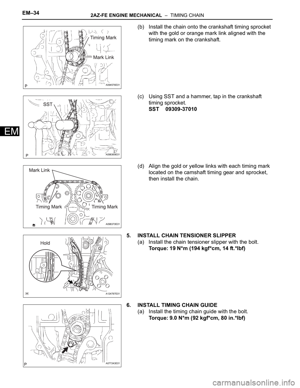
(b) Install the chain onto the crankshaft timing sprocket
with the gold or orange mark link aligned with the
timing mark on the crankshaft.
(c) Using SST and a hammer, tap in the crankshaft
timing sprocket.
SST 09309-37010
(d) Align the gold or yellow links with each timing mark
located on the camshaft timing gear and sprocket,
then install the chain.
5. INSTALL CHAIN TENSIONER SLIPPER
(a) Install the chain tensioner slipper with the bolt.
Torque: 19 N*m (194 kgf*cm, 14 ft.*lbf)
6. INSTALL TIMING CHAIN GUIDE
(a) Install the timing chain guide with the bolt.
Torque: 9.0 N*m (92 kgf*cm, 80 in.*lbf)
A094576E01
A098369E01
A098370E01
A124787E01
A077243E01
Page 592 of 2000
2AZ-FE ENGINE MECHANICAL – TIMING CHAINEM–35
EM
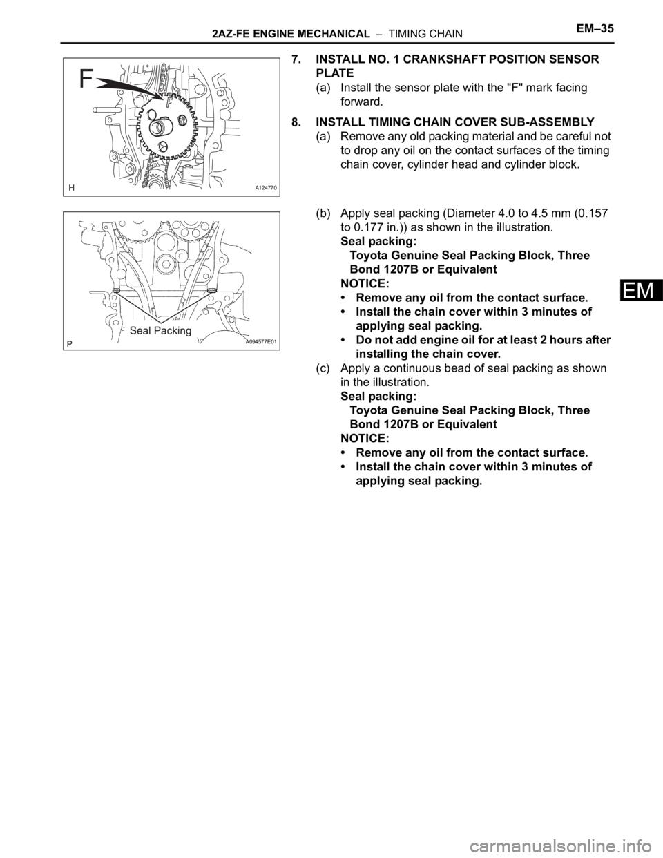
7. INSTALL NO. 1 CRANKSHAFT POSITION SENSOR
PLATE
(a) Install the sensor plate with the "F" mark facing
forward.
8. INSTALL TIMING CHAIN COVER SUB-ASSEMBLY
(a) Remove any old packing material and be careful not
to drop any oil on the contact surfaces of the timing
chain cover, cylinder head and cylinder block.
(b) Apply seal packing (Diameter 4.0 to 4.5 mm (0.157
to 0.177 in.)) as shown in the illustration.
Seal packing:
Toyota Genuine Seal Packing Block, Three
Bond 1207B or Equivalent
NOTICE:
• Remove any oil from the contact surface.
• Install the chain cover within 3 minutes of
applying seal packing.
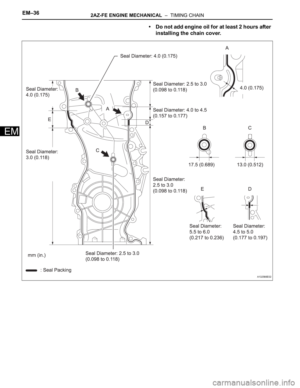
• Do not add engine oil for at least 2 hours after
installing the chain cover.
(c) Apply a continuous bead of seal packing as shown
in the illustration.
Seal packing:
Toyota Genuine Seal Packing Block, Three
Bond 1207B or Equivalent
NOTICE:
• Remove any oil from the contact surface.
• Install the chain cover within 3 minutes of
applying seal packing.
A124770
A094577E01
Page 593 of 2000
EM–362AZ-FE ENGINE MECHANICAL – TIMING CHAIN
EM
• Do not add engine oil for at least 2 hours after
installing the chain cover.
A132566E02
Page 594 of 2000
2AZ-FE ENGINE MECHANICAL – TIMING CHAINEM–37
EM
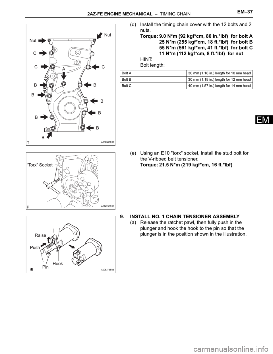
(d) Install the timing chain cover with the 12 bolts and 2
nuts.
Torque: 9.0 N*m (92 kgf*cm, 80 in.*lbf) for bolt A
25 N*m (255 kgf*cm, 18 ft.*lbf) for bolt B
55 N*m (561 kgf*cm, 41 ft.*lbf) for bolt C
11 N*m (112 kgf*cm, 8 ft.*lbf) for nut
HINT:
Bolt length:
(e) Using an E10 "torx" socket, install the stud bolt for
the V-ribbed belt tensioner.
Torque: 21.5 N*m (219 kgf*cm, 16 ft.*lbf)
9. INSTALL NO. 1 CHAIN TENSIONER ASSEMBLY
(a) Release the ratchet pawl, then fully push in the
plunger and hook the hook to the pin so that the
plunger is in the position shown in the illustration.
A132568E03
Bolt A 30 mm (1.18 in.) length for 10 mm head
Bolt B 30 mm (1.18 in.) length for 12 mm head
Bolt C 40 mm (1.57 in.) length for 14 mm head
A014253E03
A098376E03
Page 595 of 2000
EM–382AZ-FE ENGINE MECHANICAL – TIMING CHAIN
EM
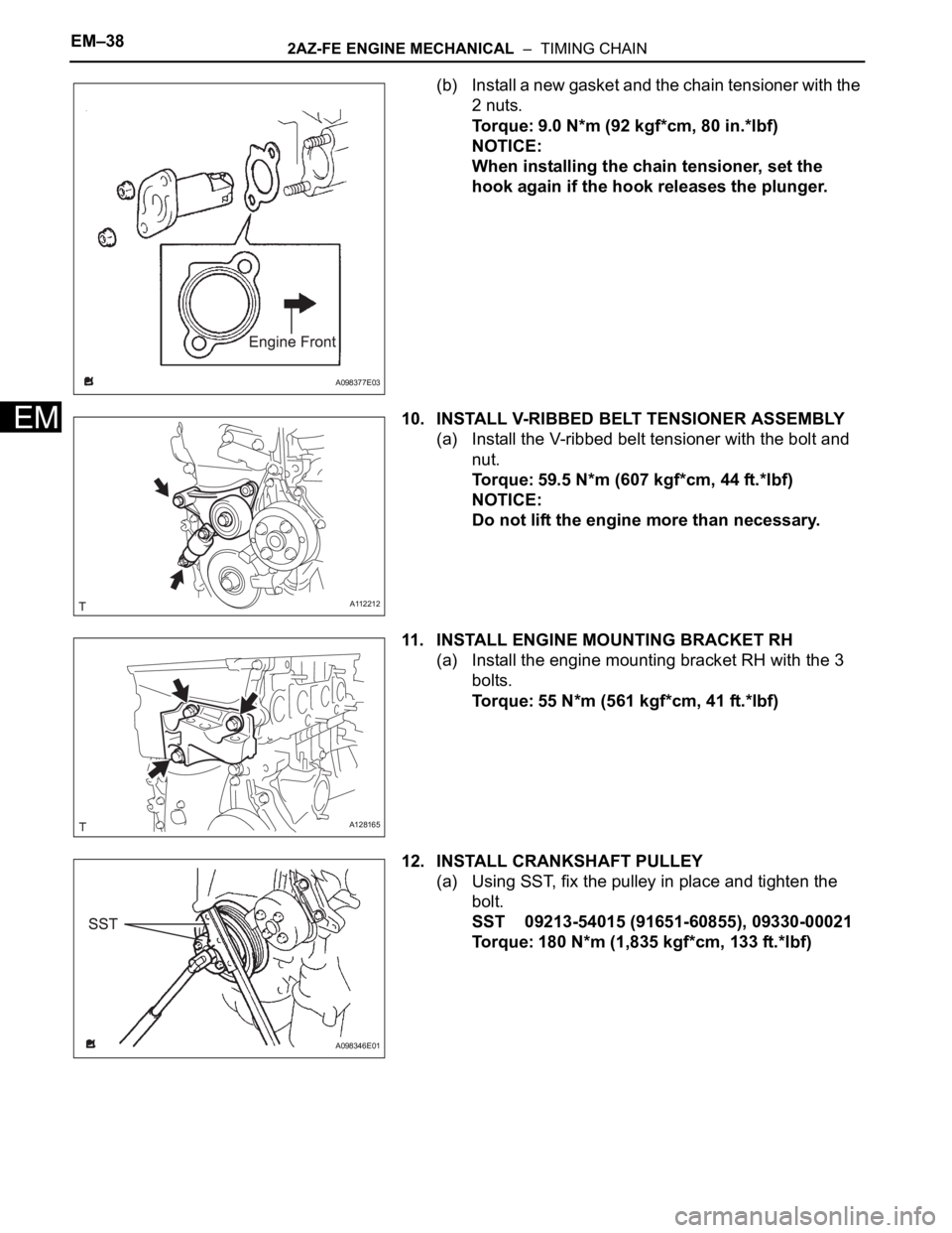
(b) Install a new gasket and the chain tensioner with the
2 nuts.
Torque: 9.0 N*m (92 kgf*cm, 80 in.*lbf)
NOTICE:
When installing the chain tensioner, set the
hook again if the hook releases the plunger.
10. INSTALL V-RIBBED BELT TENSIONER ASSEMBLY
(a) Install the V-ribbed belt tensioner with the bolt and
nut.
Torque: 59.5 N*m (607 kgf*cm, 44 ft.*lbf)
NOTICE:
Do not lift the engine more than necessary.
11. INSTALL ENGINE MOUNTING BRACKET RH
(a) Install the engine mounting bracket RH with the 3
bolts.
Torque: 55 N*m (561 kgf*cm, 41 ft.*lbf)
12. INSTALL CRANKSHAFT PULLEY
(a) Using SST, fix the pulley in place and tighten the
bolt.
SST 09213-54015 (91651-60855), 09330-00021
Torque: 180 N*m (1,835 kgf*cm, 133 ft.*lbf)
A098377E03
A112212
A128165
A098346E01
Page 596 of 2000
2AZ-FE ENGINE MECHANICAL – TIMING CHAINEM–39
EM
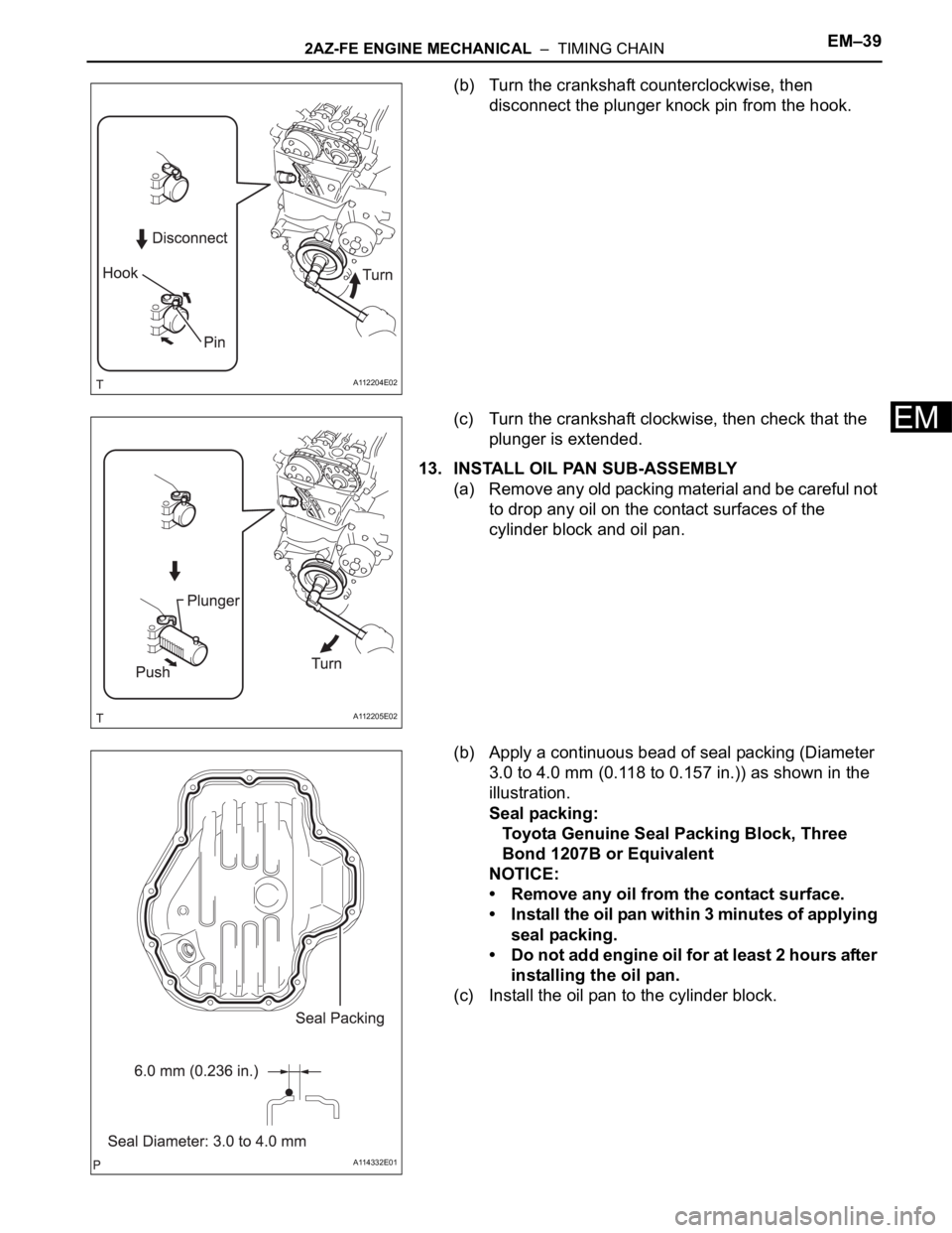
(b) Turn the crankshaft counterclockwise, then
disconnect the plunger knock pin from the hook.
(c) Turn the crankshaft clockwise, then check that the
plunger is extended.
13. INSTALL OIL PAN SUB-ASSEMBLY
(a) Remove any old packing material and be careful not
to drop any oil on the contact surfaces of the
cylinder block and oil pan.
(b) Apply a continuous bead of seal packing (Diameter
3.0 to 4.0 mm (0.118 to 0.157 in.)) as shown in the
illustration.
Seal packing:
Toyota Genuine Seal Packing Block, Three
Bond 1207B or Equivalent
NOTICE:
• Remove any oil from the contact surface.
• Instal l the oil pan wit hin 3 mi nut es of app lyi ng
seal packing.
• Do not add engine oil for at least 2 hours after
installing the oil pan.
(c) Install the oil pan to the cylinder block.
A112204E02
A112205E02
A114332E01
Page 597 of 2000

EM–402AZ-FE ENGINE MECHANICAL – TIMING CHAIN
EM
(d) Uniformly tighten the 12 bolts and 2 nuts in the
sequence shown in the illustration.
Torque: 9.0 N*m (92 kgf*cm, 80 in.*lbf)
(e) Place a transmission jack underneath the engine,
then put a wooden block on the jack.
(f) Remove the chain block and sling device.
(g) Remove the No. 1 and No. 2 engine hangers.
14. INSTALL CRANKSHAFT POSITION SENSOR (See
page ES-402)
15. INSTALL CYLINDER HEAD COVER SUB-ASSEMBLY
(a) Remove any old packing material from the contact
surface.
(b) Apply seal packing to the 2 locations shown in the
illustration.
Seal packing:
Toyota Genuine Seal Packing Block, Three
Bond 1207B or Equivalent
NOTICE:
• Remove any oil from the contact surface.
• Install the oil pan within 3 minutes of applying
seal packing.
• Do not add engine oil for at least 2 hours after
installing the oil pan.
(c) Install the cylinder head cover with the 8 bolts and 2
nuts.
Torque: 11 N*m (112 kgf*cm, 8 ft.*lbf) for bolt A
14 N*m (143 kgf*cm, 10 ft.*lbf) for bolt B
11 N*m (112 kgf*cm, 8 ft.*lbf) for nut
A114333E01
A061184E04
A094205E01
A094204E01
Page 598 of 2000
2AZ-FE ENGINE MECHANICAL – TIMING CHAINEM–41
EM
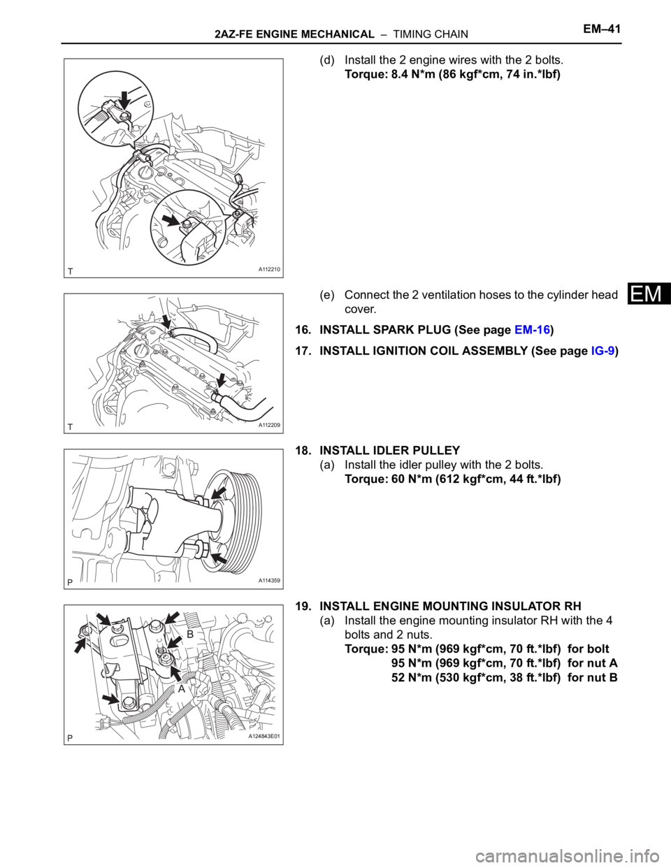
(d) Install the 2 engine wires with the 2 bolts.
Torque: 8.4 N*m (86 kgf*cm, 74 in.*lbf)
(e) Connect the 2 ventilation hoses to the cylinder head
cover.
16. INSTALL SPARK PLUG (See page EM-16)
17. INSTALL IGNITION COIL ASSEMBLY (See page IG-9)
18. INSTALL IDLER PULLEY
(a) Install the idler pulley with the 2 bolts.
Torque: 60 N*m (612 kgf*cm, 44 ft.*lbf)
19. INSTALL ENGINE MOUNTING INSULATOR RH
(a) Install the engine mounting insulator RH with the 4
bolts and 2 nuts.
Torque: 95 N*m (969 kgf*cm, 70 ft.*lbf) for bolt
95 N*m (969 kgf*cm, 70 ft.*lbf) for nut A
52 N*m (530 kgf*cm, 38 ft.*lbf) for nut B
A112210
A112209
A114359
A124843E01
Page 599 of 2000
EM–422AZ-FE ENGINE MECHANICAL – TIMING CHAIN
EM
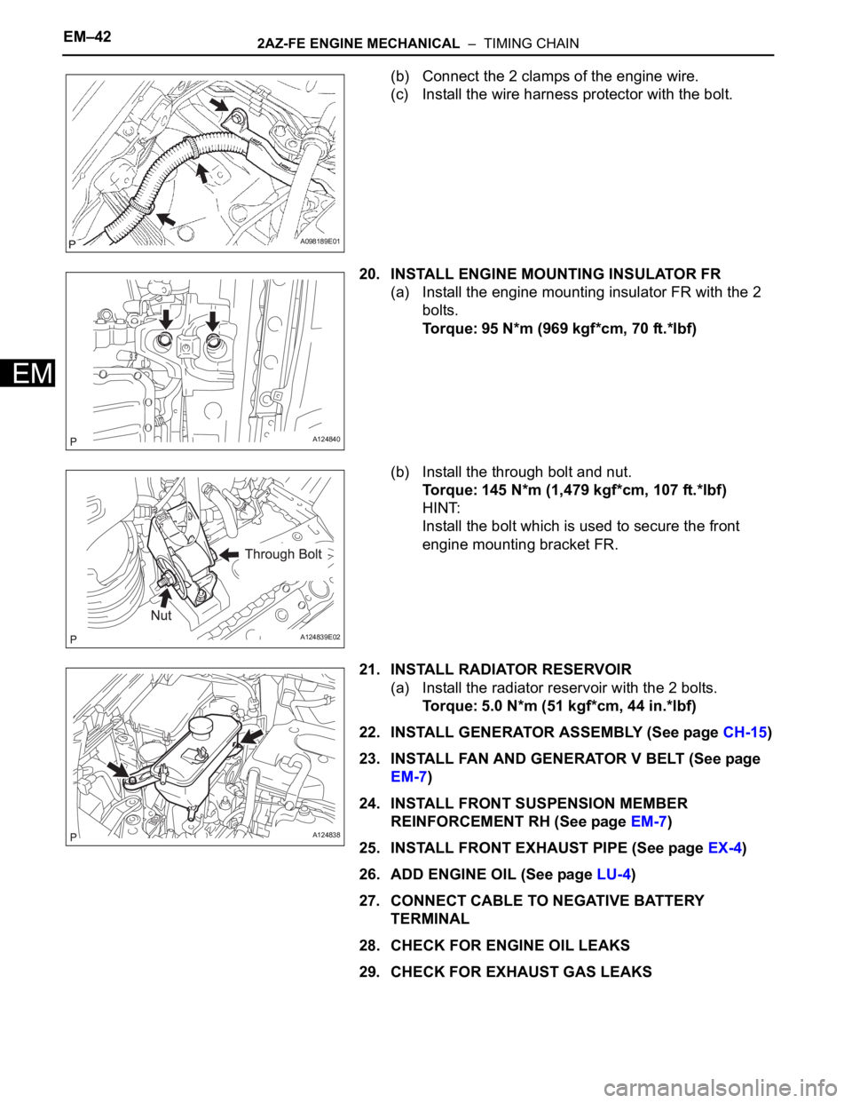
(b) Connect the 2 clamps of the engine wire.
(c) Install the wire harness protector with the bolt.
20. INSTALL ENGINE MOUNTING INSULATOR FR
(a) Install the engine mounting insulator FR with the 2
bolts.
Torque: 95 N*m (969 kgf*cm, 70 ft.*lbf)
(b) Install the through bolt and nut.
Torque: 145 N*m (1,479 kgf*cm, 107 ft.*lbf)
HINT:
Install the bolt which is used to secure the front
engine mounting bracket FR.
21. INSTALL RADIATOR RESERVOIR
(a) Install the radiator reservoir with the 2 bolts.
Torque: 5.0 N*m (51 kgf*cm, 44 in.*lbf)
22. INSTALL GENERATOR ASSEMBLY (See page CH-15)
23. INSTALL FAN AND GENERATOR V BELT (See page
EM-7)
24. INSTALL FRONT SUSPENSION MEMBER
REINFORCEMENT RH (See page EM-7)
25. INSTALL FRONT EXHAUST PIPE (See page EX-4)
26. ADD ENGINE OIL (See page LU-4)
27. CONNECT CABLE TO NEGATIVE BATTERY
TERMINAL
28. CHECK FOR ENGINE OIL LEAKS
29. CHECK FOR EXHAUST GAS LEAKS
A098189E01
A124840
A124839E02
A124838
Page 600 of 2000
2AZ-FE ENGINE MECHANICAL – TIMING CHAINEM–43
EM
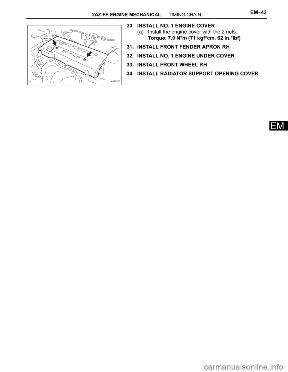
30. INSTALL NO. 1 ENGINE COVER
(a) Install the engine cover with the 2 nuts.
Torque: 7.0 N*m (71 kgf*cm, 62 in.*lbf)
31. INSTALL FRONT FENDER APRON RH
32. INSTALL NO. 1 ENGINE UNDER COVER
33. INSTALL FRONT WHEEL RH
34. INSTALL RADIATOR SUPPORT OPENING COVER
A112206
Trending: height, Oxygen sensor, tow bar, roof, Engine cover, oil reset, ignition lock cylinder
