TOYOTA RAV4 2006 Service Repair Manual
Manufacturer: TOYOTA, Model Year: 2006, Model line: RAV4, Model: TOYOTA RAV4 2006Pages: 2000, PDF Size: 45.84 MB
Page 671 of 2000
EM–1442AZ-FE ENGINE MECHANICAL – ENGINE UNIT
EM
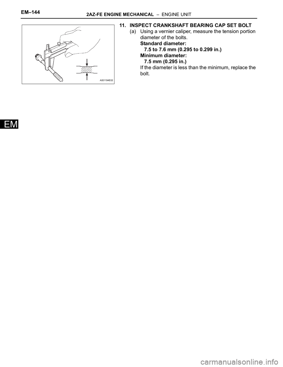
11. INSPECT CRANKSHAFT BEARING CAP SET BOLT
(a) Using a vernier caliper, measure the tension portion
diameter of the bolts.
Standard diameter:
7.5 to 7.6 mm (0.295 to 0.299 in.)
Minimum diameter:
7.5 mm (0.295 in.)
If the diameter is less than the minimum, replace the
bolt.
A001194E02
Page 672 of 2000
2AZ-FE ENGINE MECHANICAL – ENGINE UNITEM–145
EM
REPLACEMENT
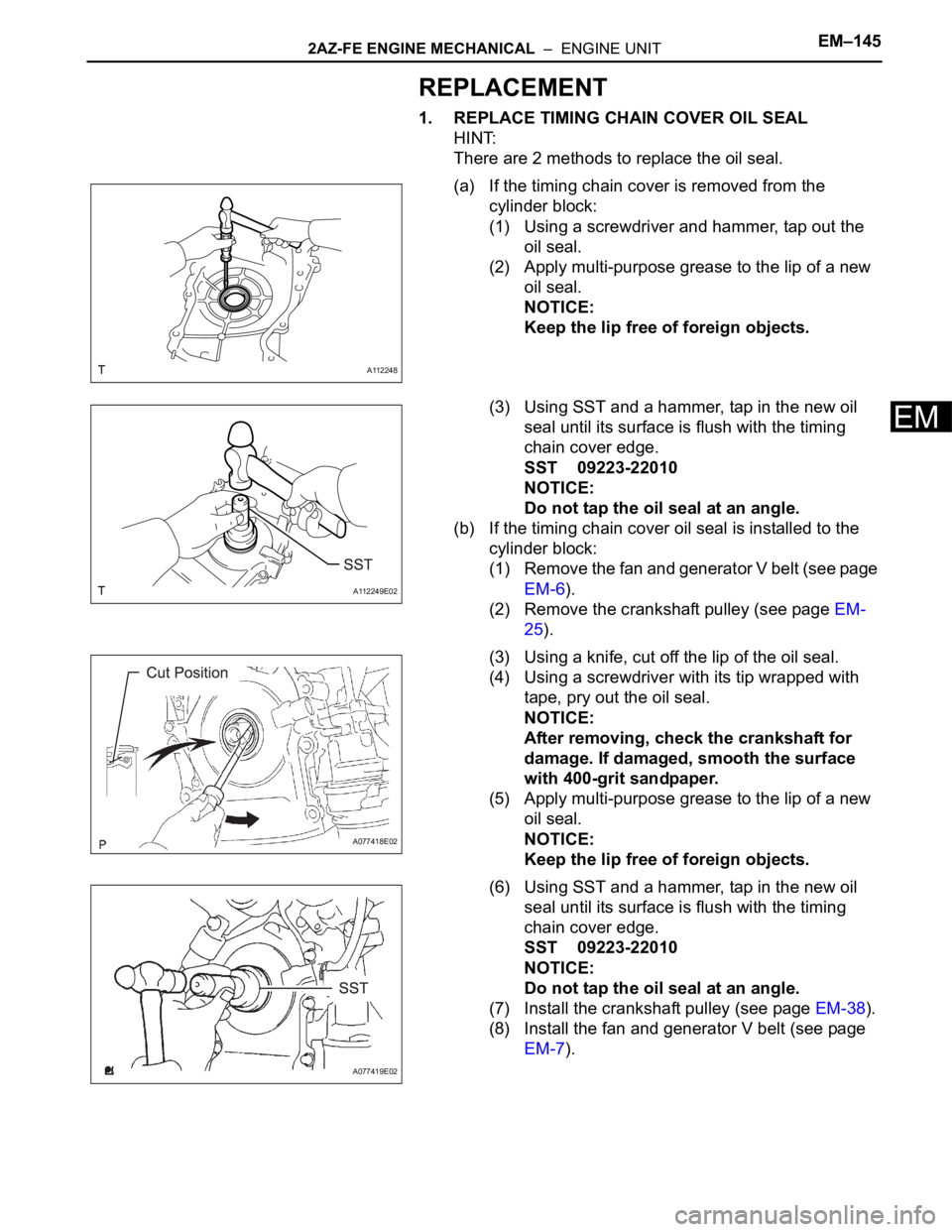
1. REPLACE TIMING CHAIN COVER OIL SEAL
HINT:
There are 2 methods to replace the oil seal.
(a) If the timing chain cover is removed from the
cylinder block:
(1) Using a screwdriver and hammer, tap out the
oil seal.
(2) Apply multi-purpose grease to the lip of a new
oil seal.
NOTICE:
Keep the lip free of foreign objects.
(3) Using SST and a hammer, tap in the new oil
seal until its surface is flush with the timing
chain cover edge.
SST 09223-22010
NOTICE:
Do not tap the oil seal at an angle.
(b) If the timing chain cover oil seal is installed to the
cylinder block:
(1) Remove the fan and generator V belt (see page
EM-6).
(2) Remove the crankshaft pulley (see page EM-
25).
(3) Using a knife, cut off the lip of the oil seal.
(4) Using a screwdriver with its tip wrapped with
tape, pry out the oil seal.
NOTICE:
After removing, check the crankshaft for
damage. If damaged, smooth the surface
with 400-grit sandpaper.
(5) Apply multi-purpose grease to the lip of a new
oil seal.
NOTICE:
Keep the lip free of foreign objects.
(6) Using SST and a hammer, tap in the new oil
seal until its surface is flush with the timing
chain cover edge.
SST 09223-22010
NOTICE:
Do not tap the oil seal at an angle.
(7) Install the crankshaft pulley (see page EM-38).
(8) Install the fan and generator V belt (see page
EM-7).
A112248
A112249E02
A077418E02
A077419E02
Page 673 of 2000
EM–1462AZ-FE ENGINE MECHANICAL – ENGINE UNIT
EM
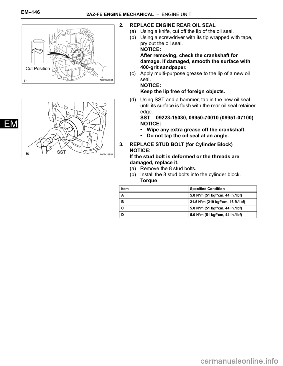
2. REPLACE ENGINE REAR OIL SEAL
(a) Using a knife, cut off the lip of the oil seal.
(b) Using a screwdriver with its tip wrapped with tape,
pry out the oil seal.
NOTICE:
After removing, check the crankshaft for
damage. If damaged, smooth the surface with
400-grit sandpaper.
(c) Apply multi-purpose grease to the lip of a new oil
seal.
NOTICE:
Keep the lip free of foreign objects.
(d) Using SST and a hammer, tap in the new oil seal
until its surface is flush with the rear oil seal retainer
edge.
SST 09223-15030, 09950-70010 (09951-07100)
NOTICE:
• Wipe any extra grease off the crankshaft.
• Do not tap the oil seal at an angle.
3. REPLACE STUD BOLT (for Cylinder Block)
NOTICE:
If the stud bolt is deformed or the threads are
damaged, replace it.
(a) Remove the 8 stud bolts.
(b) Install the 8 stud bolts into the cylinder block.
To r q u e
A098356E01
A077422E01
Item Specified Condition
A 5.0 N*m (51 kgf*cm, 44 in.*lbf)
B 21.5 N*m (219 kgf*cm, 16 ft.*lbf)
C 5.0 N*m (51 kgf*cm, 44 in.*lbf)
D 5.0 N*m (51 kgf*cm, 44 in.*lbf)
Page 674 of 2000
2AZ-FE ENGINE MECHANICAL – ENGINE UNITEM–147
EM
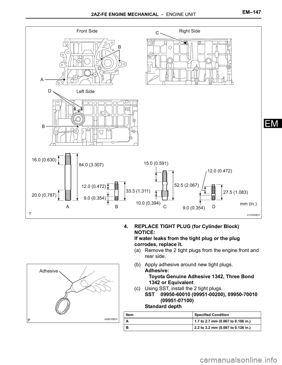
4. REPLACE TIGHT PLUG (for Cylinder Block)
NOTICE:
If water leaks from the tight plug or the plug
corrodes, replace it.
(a) Remove the 2 tight plugs from the engine front and
rear side.
(b) Apply adhesive around new tight plugs.
Adhesive:
Toyota Genuine Adhesive 1342, Three Bond
1342 or Equivalent
(c) Using SST, install the 2 tight plugs.
SST 09950-60010 (09951-00200), 09950-70010
(09951-07100)
Standard depth
A112253E01
A058129E01Item Specified Condition
A 1.7 to 2.7 mm (0.067 to 0.106 in.)
B 2.2 to 3.2 mm (0.087 to 0.126 in.)
Page 675 of 2000
EM–1482AZ-FE ENGINE MECHANICAL – ENGINE UNIT
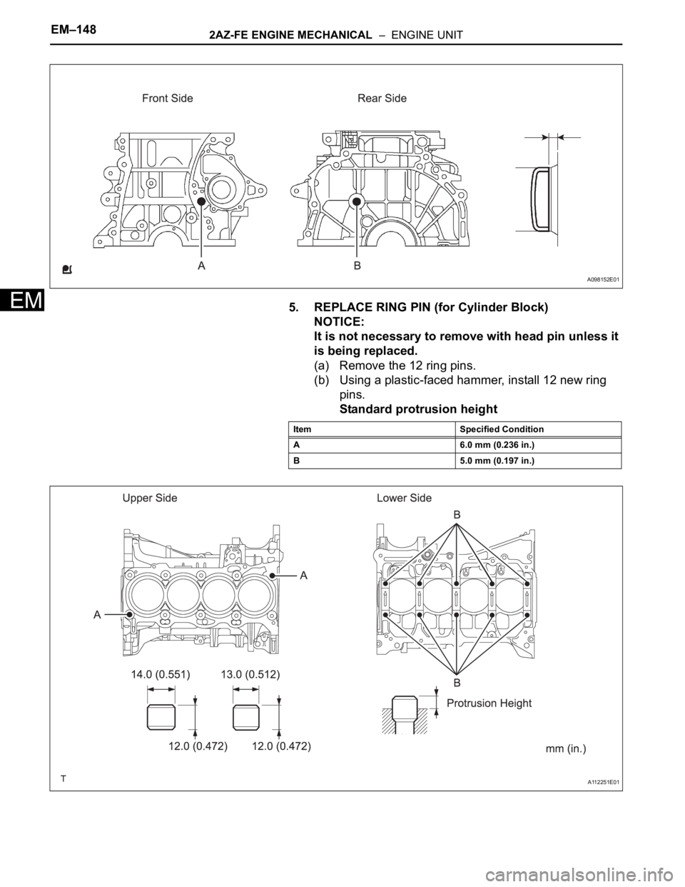
EM5. REPLACE RING PIN (for Cylinder Block)
NOTICE:
It is not necessary to remove with head pin unless it
is being replaced.
(a) Remove the 12 ring pins.
(b) Using a plastic-faced hammer, install 12 new ring
pins.
Standard protrusion height
A098152E01
Item Specified Condition
A 6.0 mm (0.236 in.)
B 5.0 mm (0.197 in.)
A112251E01
Page 676 of 2000
2AZ-FE ENGINE MECHANICAL – ENGINE UNITEM–149
EM
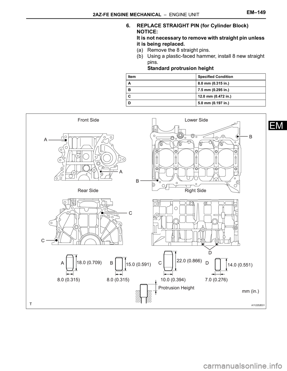
6. REPLACE STRAIGHT PIN (for Cylinder Block)
NOTICE:
It is not necessary to remove with straight pin unless
it is being replaced.
(a) Remove the 8 straight pins.
(b) Using a plastic-faced hammer, install 8 new straight
pins.
Standard protrusion height
Item Specified Condition
A 8.0 mm (0.315 in.)
B 7.5 mm (0.295 in.)
C 12.0 mm (0.472 in.)
D 5.0 mm (0.197 in.)
A112252E01
Page 677 of 2000
2GR-FE ENGINE MECHANICAL – ENGINE ASSEMBLYEM–31
EM
INSTALLATION
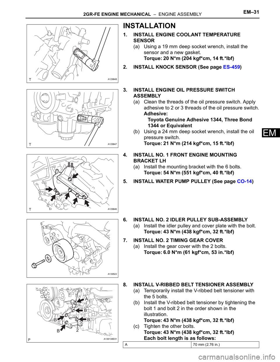
1. INSTALL ENGINE COOLANT TEMPERATURE
SENSOR
(a) Using a 19 mm deep socket wrench, install the
sensor and a new gasket.
Torque: 20 N*m (204 kgf*cm, 14 ft.*lbf)
2. INSTALL KNOCK SENSOR (See page ES-459)
3. INSTALL ENGINE OIL PRESSURE SWITCH
ASSEMBLY
(a) Clean the threads of the oil pressure switch. Apply
adhesive to 2 or 3 threads of the oil pressure switch.
Adhesive:
Toyota Genuine Adhesive 1344, Three Bond
1344 or Equivalent
(b) Using a 24 mm deep socket wrench, install the oil
pressure switch.
Torque: 21 N*m (214 kgf*cm, 15 ft.*lbf)
4. INSTALL NO. 1 FRONT ENGINE MOUNTING
BRACKET LH
(a) Install the mounting bracket with the 6 bolts.
Torque: 54 N*m (551 kgf*cm, 40 ft.*lbf)
5. INSTALL WATER PUMP PULLEY (See page CO-14)
6. INSTALL NO. 2 IDLER PULLEY SUB-ASSEMBLY
(a) Install the idler pulley and cover plate with the bolt.
Torque: 43 N*m (438 kgf*cm, 32 ft.*lbf)
7. INSTALL NO. 2 TIMING GEAR COVER
(a) Install the gear cover with the 2 bolts.
Torque: 6.0 N*m (61 kgf*cm, 53 in.*lbf)
8. INSTALL V-RIBBED BELT TENSIONER ASSEMBLY
(a) Temporarily install the V-ribbed belt tensioner with
the 5 bolts.
(b) Install the V-ribbed belt tensioner by tightening the
bolt 1 and bolt 2 in the order shown in the
illustration.
Torque: 43 N*m (438 kgf*cm, 32 ft.*lbf)
(c) Tighten the other bolts.
Torque: 43 N*m (438 kgf*cm, 32 ft.*lbf)
Each bolt length is as follows:
A129648
A129647
A129646
A139522
A139138E01
A 70 mm (2.76 in.)
Page 678 of 2000
EM–322GR-FE ENGINE MECHANICAL – ENGINE ASSEMBLY
EM
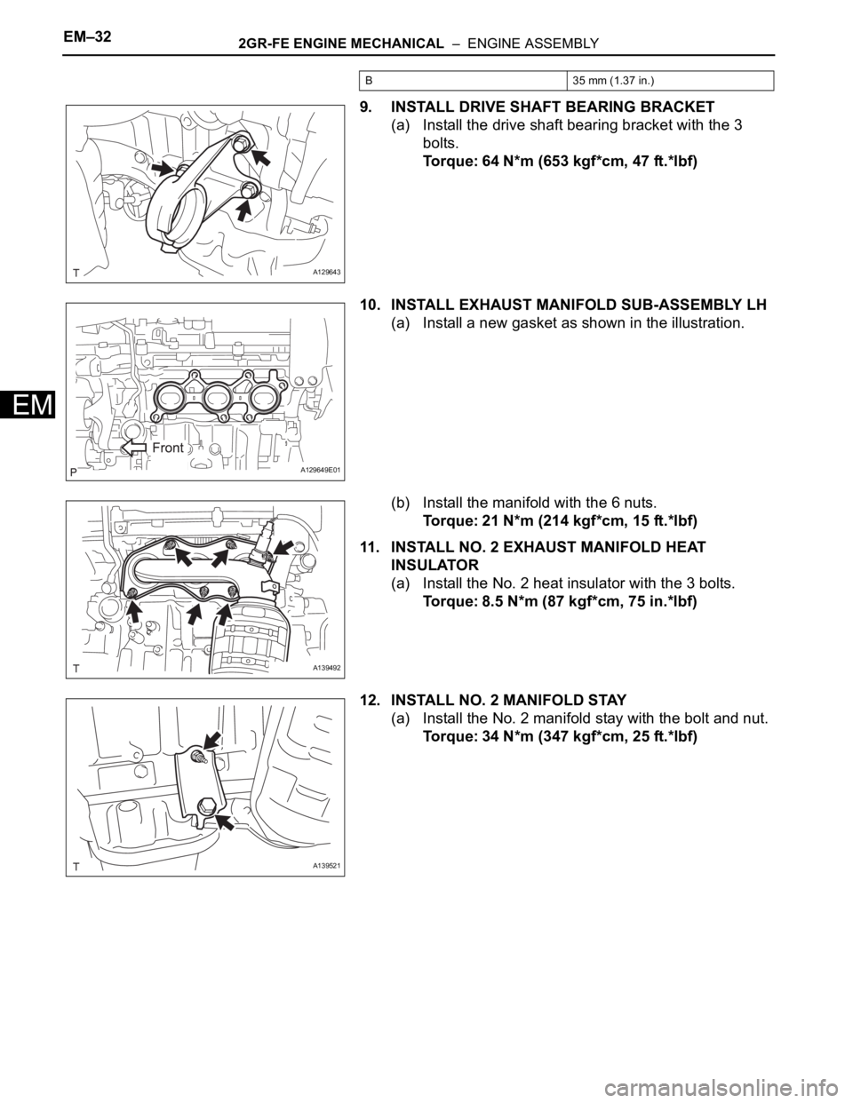
9. INSTALL DRIVE SHAFT BEARING BRACKET
(a) Install the drive shaft bearing bracket with the 3
bolts.
Torque: 64 N*m (653 kgf*cm, 47 ft.*lbf)
10. INSTALL EXHAUST MANIFOLD SUB-ASSEMBLY LH
(a) Install a new gasket as shown in the illustration.
(b) Install the manifold with the 6 nuts.
Torque: 21 N*m (214 kgf*cm, 15 ft.*lbf)
11. INSTALL NO. 2 EXHAUST MANIFOLD HEAT
INSULATOR
(a) Install the No. 2 heat insulator with the 3 bolts.
Torque: 8.5 N*m (87 kgf*cm, 75 in.*lbf)
12. INSTALL NO. 2 MANIFOLD STAY
(a) Install the No. 2 manifold stay with the bolt and nut.
Torque: 34 N*m (347 kgf*cm, 25 ft.*lbf)
B 35 mm (1.37 in.)
A129643
A129649E01
A139492
A139521
Page 679 of 2000
2GR-FE ENGINE MECHANICAL – ENGINE ASSEMBLYEM–33
EM
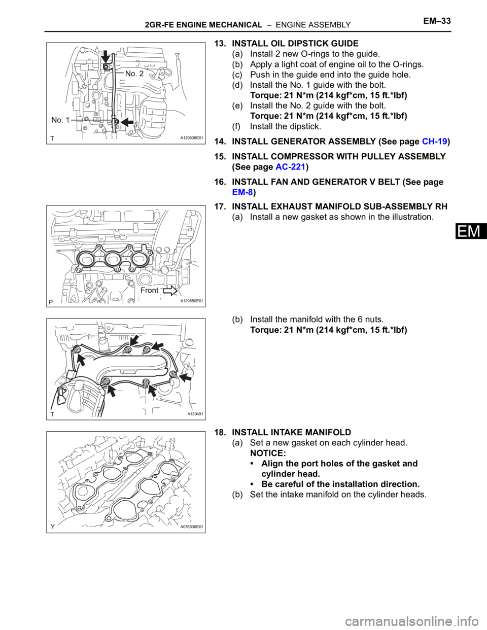
13. INSTALL OIL DIPSTICK GUIDE
(a) Install 2 new O-rings to the guide.
(b) Apply a light coat of engine oil to the O-rings.
(c) Push in the guide end into the guide hole.
(d) Install the No. 1 guide with the bolt.
Torque: 21 N*m (214 kgf*cm, 15 ft.*lbf)
(e) Install the No. 2 guide with the bolt.
Torque: 21 N*m (214 kgf*cm, 15 ft.*lbf)
(f) Install the dipstick.
14. INSTALL GENERATOR ASSEMBLY (See page CH-19)
15. INSTALL COMPRESSOR WITH PULLEY ASSEMBLY
(See page AC-221)
16. INSTALL FAN AND GENERATOR V BELT (See page
EM-8)
17. INSTALL EXHAUST MANIFOLD SUB-ASSEMBLY RH
(a) Install a new gasket as shown in the illustration.
(b) Install the manifold with the 6 nuts.
Torque: 21 N*m (214 kgf*cm, 15 ft.*lbf)
18. INSTALL INTAKE MANIFOLD
(a) Set a new gasket on each cylinder head.
NOTICE:
• Align the port holes of the gasket and
cylinder head.
• Be careful of the installation direction.
(b) Set the intake manifold on the cylinder heads.
A129638E01
A129650E01
A139491
A076536E01
Page 680 of 2000
EM–342GR-FE ENGINE MECHANICAL – ENGINE ASSEMBLY
EM
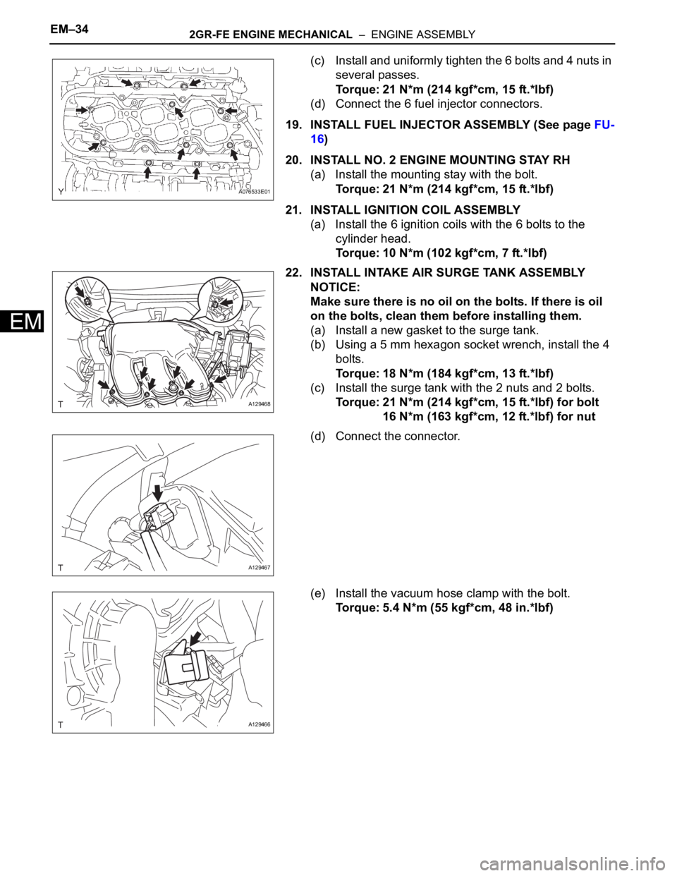
(c) Install and uniformly tighten the 6 bolts and 4 nuts in
several passes.
Torque: 21 N*m (214 kgf*cm, 15 ft.*lbf)
(d) Connect the 6 fuel injector connectors.
19. INSTALL FUEL INJECTOR ASSEMBLY (See page FU-
16)
20. INSTALL NO. 2 ENGINE MOUNTING STAY RH
(a) Install the mounting stay with the bolt.
Torque: 21 N*m (214 kgf*cm, 15 ft.*lbf)
21. INSTALL IGNITION COIL ASSEMBLY
(a) Install the 6 ignition coils with the 6 bolts to the
cylinder head.
Torque: 10 N*m (102 kgf*cm, 7 ft.*lbf)
22. INSTALL INTAKE AIR SURGE TANK ASSEMBLY
NOTICE:
Make sure there is no oil on the bolts. If there is oil
on the bolts, clean them before installing them.
(a) Install a new gasket to the surge tank.
(b) Using a 5 mm hexagon socket wrench, install the 4
bolts.
Torque: 18 N*m (184 kgf*cm, 13 ft.*lbf)
(c) Install the surge tank with the 2 nuts and 2 bolts.
Torque: 21 N*m (214 kgf*cm, 15 ft.*lbf) for bolt
16 N*m (163 kgf*cm, 12 ft.*lbf) for nut
(d) Connect the connector.
(e) Install the vacuum hose clamp with the bolt.
Torque: 5.4 N*m (55 kgf*cm, 48 in.*lbf)
A076533E01
A129468
A129467
A129466