ACURA NSX 1997 Service Repair Manual
Manufacturer: ACURA, Model Year: 1997, Model line: NSX, Model: ACURA NSX 1997Pages: 1503, PDF Size: 57.08 MB
Page 1381 of 1503
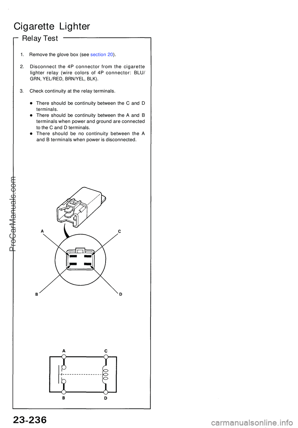
1. Remov e th e glov e bo x (se e sectio n 20 ).
2 . Disconnec t th e 4 P connecto r fro m th e cigarett e
lighte r rela y (wir e color s of 4P connector : BLU /
GRN, YEL/RED , BRN/YEL , BLK) .
3. Chec k continuit y a t th e rela y terminals .
Ther e shoul d b e continuit y betwee n th e C an d D
terminals .
There shoul d b e continuit y betwee n th e A an d B
terminal s whe n powe r an d groun d ar e connecte d
t o th e C an d D terminals .
Ther e shoul d b e n o continuit y betwee n th e A
an d B terminal s whe n powe r i s disconnected .
Cigarette Lighte r
Relay Tes t
ProCarManuals.com
Page 1382 of 1503
Stereo Soun d Syste m
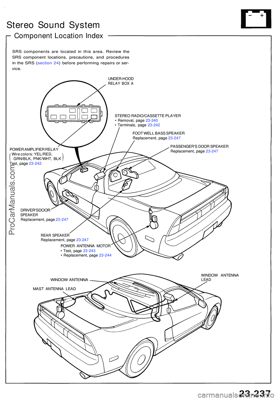
Componen t Locatio n Inde x
SRS component s ar e locate d i n thi s area . Revie w th e
SR S componen t locations , precautions , an d procedure s
i n th e SR S ( sectio n 24 ) befor e performin g repair s o r ser -
vice .
UNDER-HOO DRELAY BO X A
STERE O RADIO/CASSETT E PLAYE R
• Removal , pag e 23-24 0
• Terminals , pag e 23-24 2
FOO T WEL L BAS S SPEAKE R
Replacement , pag e 23-247
POWE R AMPLIFIE R RELA Y
Wir e colors : YEL/RED ,
GRN/BLK , PNK/WHT , BL K
Test , pag e 23-24 2 PASSENGER'
S DOO R SPEAKE R
Replacement , pag e 23-24 7
DRIVER'SDOO RSPEAKERReplacement , pag e 23-24 7
REAR SPEAKE RReplacement , pag e 23-24 7
POWE R ANTENN A MOTO R
• Test , pag e 23-24 3
• Replacement , pag e 23-24 4
WINDO W ANTENN A
MAST ANTENN A LEA D WINDO
W ANTENN A
LEAD
ProCarManuals.com
Page 1383 of 1503
Stereo Soun d Syste m
Unit Remova l
SRS component s ar e locate d i n thi s area . Revie w th e
SR S componen t locations , precautions , an d procedure s
i n th e SR S sectio n 24 befor e performin g repair s o r ser -
vice .
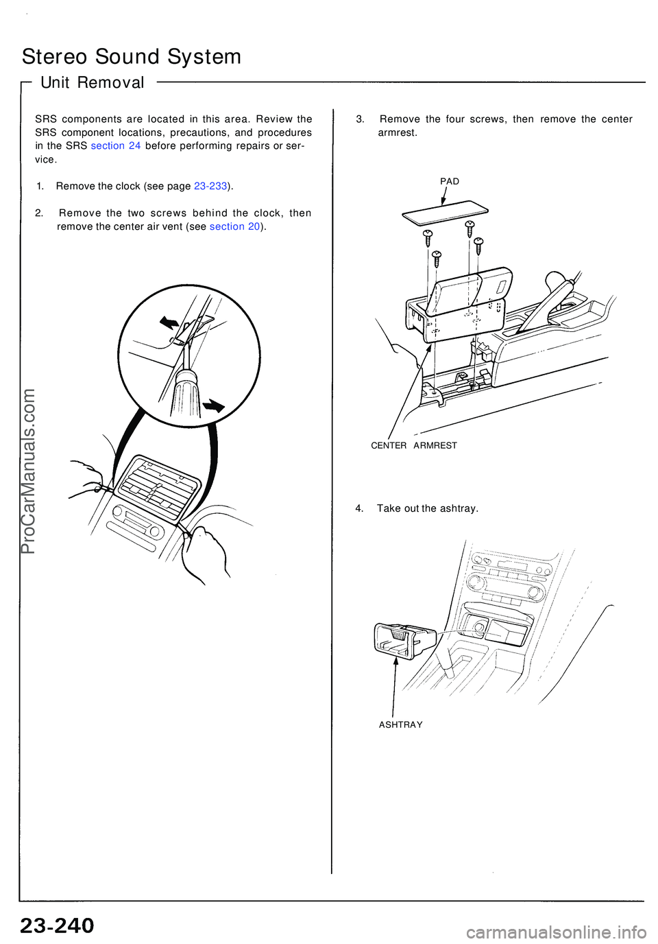
1. Remov e th e cloc k (se e pag e 23-233 ).
2 . Remov e th e tw o screw s behin d th e clock , the n
remov e th e cente r ai r ven t (se e sectio n 20 ). 3
. Remov e th e fou r screws , the n remov e th e cente r
armrest .PAD
CENTE R ARMRES T
4. Tak e ou t th e ashtray .
ASHTRA Y
ProCarManuals.com
Page 1384 of 1503
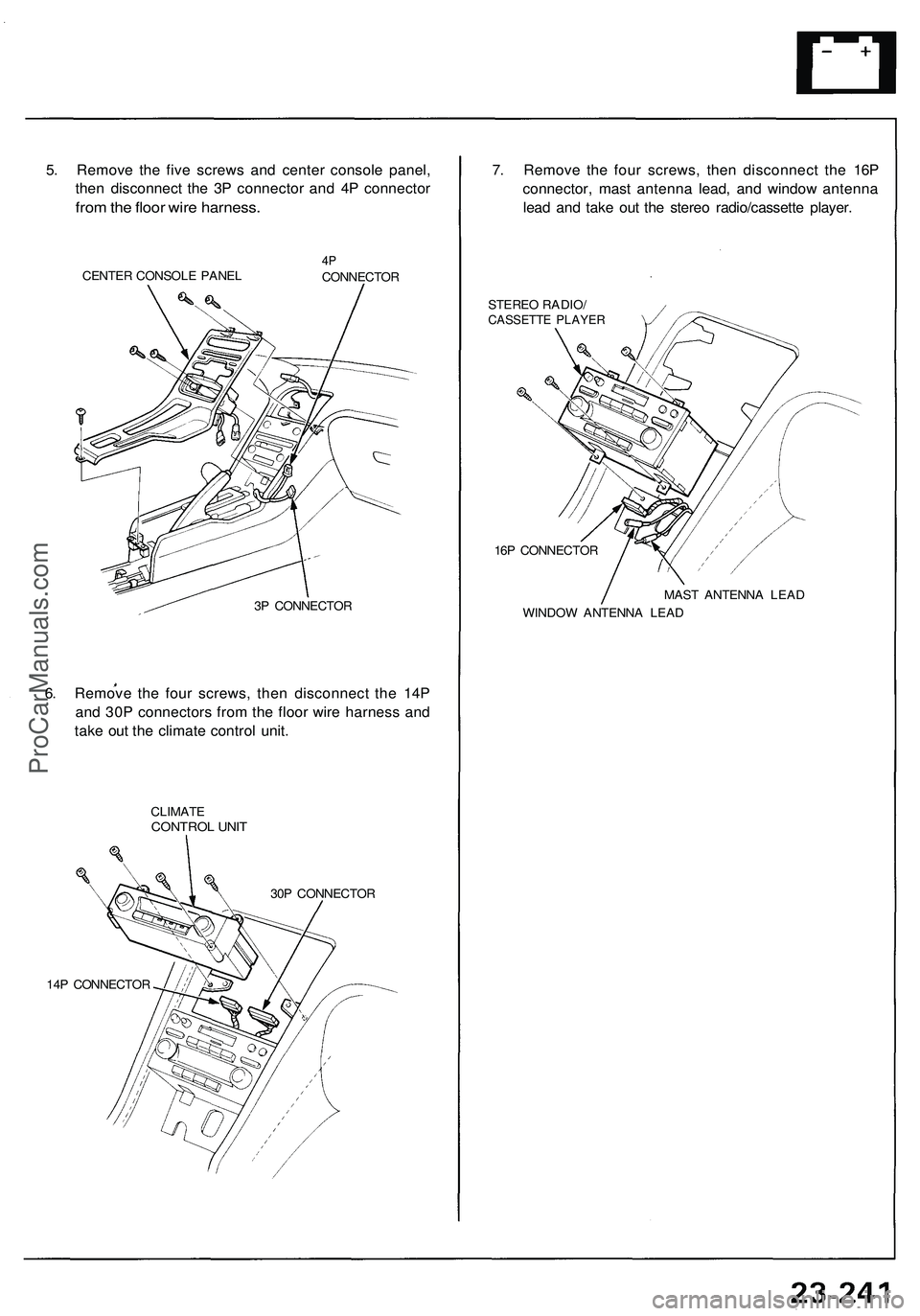
5. Remove the five screws and center console panel,
then disconnect the 3P connector and 4P connector
from the floor wire harness.
CENTER CONSOLE PANEL
4P
CONNECTOR
3P CONNECTOR
6. Remove the four screws, then disconnect the 14P
and 30P connectors from the floor wire harness and
take out the climate control unit.
CLIMATE
CONTROL UNIT
30P CONNECTOR
14P CONNECTOR
7. Remove the four screws, then disconnect the 16P
connector, mast antenna lead, and window antenna
lead and take out the stereo radio/cassette player.
STEREO RADIO/
CASSETTE PLAYER
16P CONNECTOR
WINDOW ANTENNA LEAD
MAST ANTENNA LEADProCarManuals.com
Page 1385 of 1503
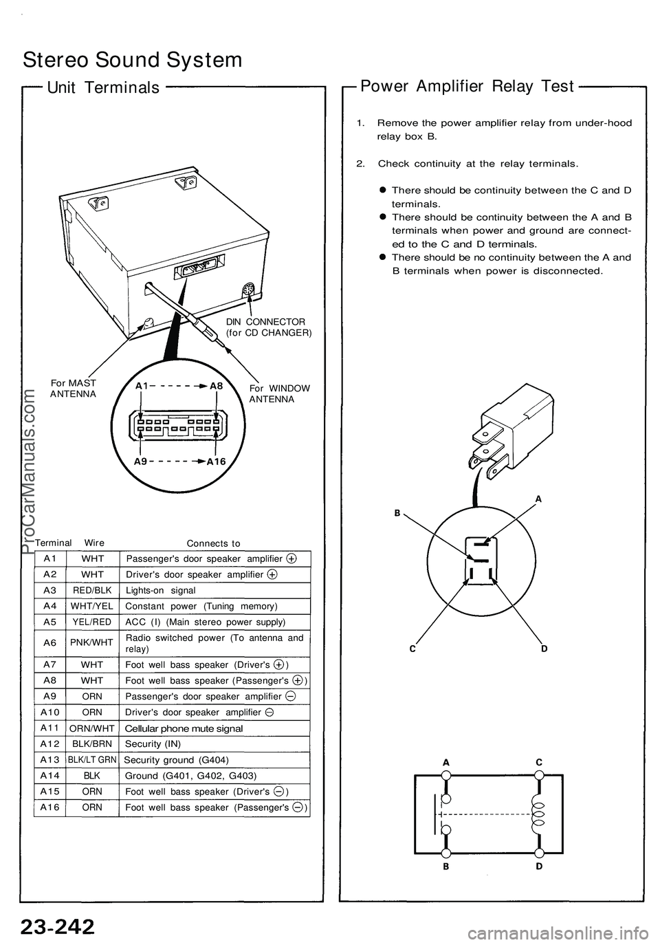
Stereo Sound System
Unit Terminals
For MAST
ANTENNA
DIN CONNECTOR
(for CD CHANGER)
For WINDOW
ANTENNA
Terminal Wire
Connects to
A1
A2
A3
A4
A5
A6
A7
A8
A9
A10
A11
A12
A13
A14
A15
A16
WHT
WHT
RED/BLK
WHT/YEL
YEL/RED
PNK/WHT
WHT
WHT
ORN
ORN
ORN/WHT
BLK/BRN
BLK/LT GRN
BLK
ORN
ORN
Passenger's door speaker amplifier
Driver's door speaker amplifier
Lights-on signal
Constant power (Tuning memory)
ACC (I) (Main stereo power supply)
Radio switched power (To antenna and
relay)
Foot well bass speaker (Driver's )
Foot well bass speaker (Passenger's )
Passenger's door speaker amplifier
Driver's door speaker amplifier
Cellular phone mute signal
Security (IN)
Security ground (G404)
Ground (G401, G402, G403)
Foot well bass speaker (Driver's )
Foot well bass speaker (Passenger's )
Power Amplifier Relay Test
1. Remove the power amplifier relay from under-hood
relay box B.
2. Check continuity at the relay terminals.
There should be continuity between the C and D
terminals.
There should be continuity between the A and B
terminals when power and ground are connect-
ed to the C and D terminals.
There should be no continuity between the A and
B terminals when power is disconnected.ProCarManuals.com
Page 1386 of 1503
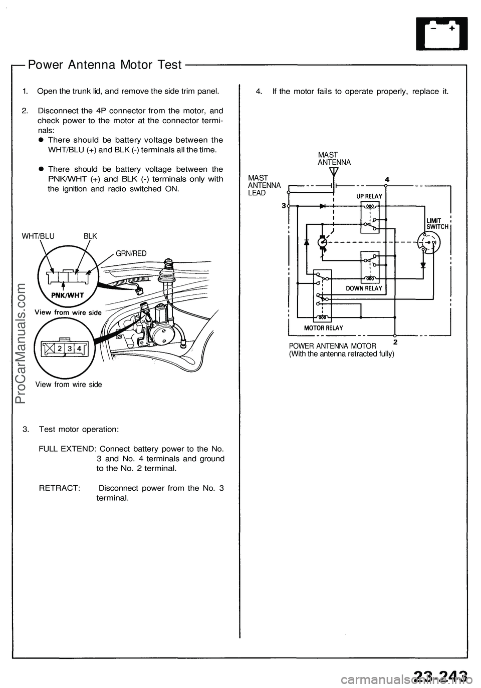
— Power Antenna Motor Test
1. Open the trunk lid, and remove the side trim panel.
2. Disconnect the 4P connector from the motor, and
check power to the motor at the connector termi-
nals:
There should be battery voltage between the
WHT/BLU (+) and BLK (-) terminals all the time.
There should be battery voltage between the
PNK/WHT (+) and BLK (-) terminals only with
the ignition and radio switched ON.
WHT/BLU BLK
View from wire side
3. Test motor operation:
FULL EXTEND: Connect battery power to the No.
3 and No. 4 terminals and ground
to the No. 2 terminal.
RETRACT: Disconnect power from the No. 3
terminal.
4. If the motor fails to operate properly, replace it.
MAST
ANTENNA
MAST
ANTENNA
LEAD
POWER ANTENNA MOTOR
(With the antenna retracted fully)
GRN/REDProCarManuals.com
Page 1387 of 1503
Stereo Soun d Syste m
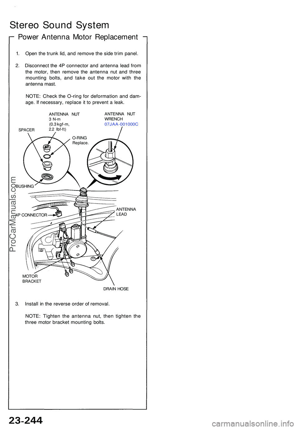
Power Antenn a Moto r Replacemen t
1. Ope n th e trun k lid , an d remov e th e sid e tri m panel .
2 . Disconnec t th e 4 P connecto r an d antenn a lea d fro m
th e motor , the n remov e th e antenn a nu t an d thre e
mountin g bolts , an d tak e ou t th e moto r wit h th e
antenn a mast .
NOTE : Chec k th e O-rin g fo r deformatio n an d dam -
age. I f necessary , replac e i t t o preven t a leak .
SPACE R
ANTENN A NU T3 N- m(0.3 kgf-m ,2.2 Ibf-ft )
ANTENN A NU T
WRENC H
07JAA-001000 C
BUSHING
4 P CONNECTO R ANTENN
A
LEAD
MOTO RBRACKE T
DRAIN HOS E
3. Instal l i n th e revers e orde r o f removal .
NOTE : Tighte n th e antenn a nut , the n tighte n th e
thre e moto r bracke t mountin g bolts .
O-RIN GReplace .
ProCarManuals.com
Page 1388 of 1503
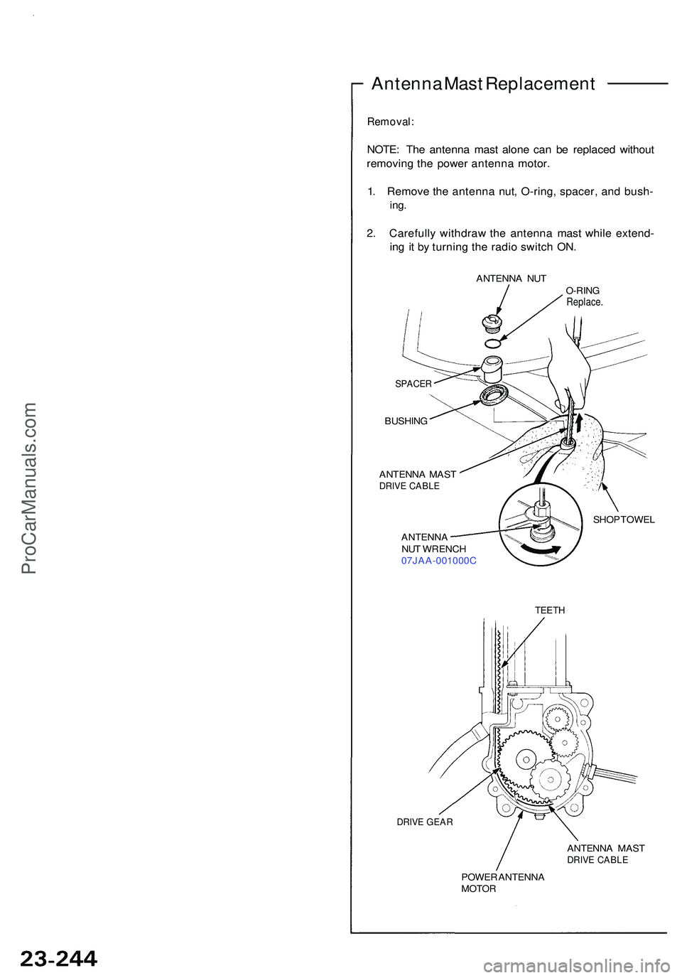
Antenna Mas t Replacemen t
Removal:
NOTE: Th e antenn a mas t alone can be replace d withou t
removin g th e powe r antenn a motor .
1 . Remov e th e antenn a nut , O-ring , spacer , an d bush -
ing.
2. Carefull y withdra w th e antenn a mas t whil e extend -
in g i t b y turnin g th e radi o switc h ON .
ANTENN A NU TO-RIN GReplace .
SPACER
BUSHIN G
ANTENN A MAS T
DRIVE CABL E
ANTENN ANUT WRENC H
07JAA-001000 C SHO
P TOWE L
TEETH
DRIVE GEA R
ANTENN A MAS TDRIVE CABL E
POWER ANTENN AMOTOR
ProCarManuals.com
Page 1389 of 1503
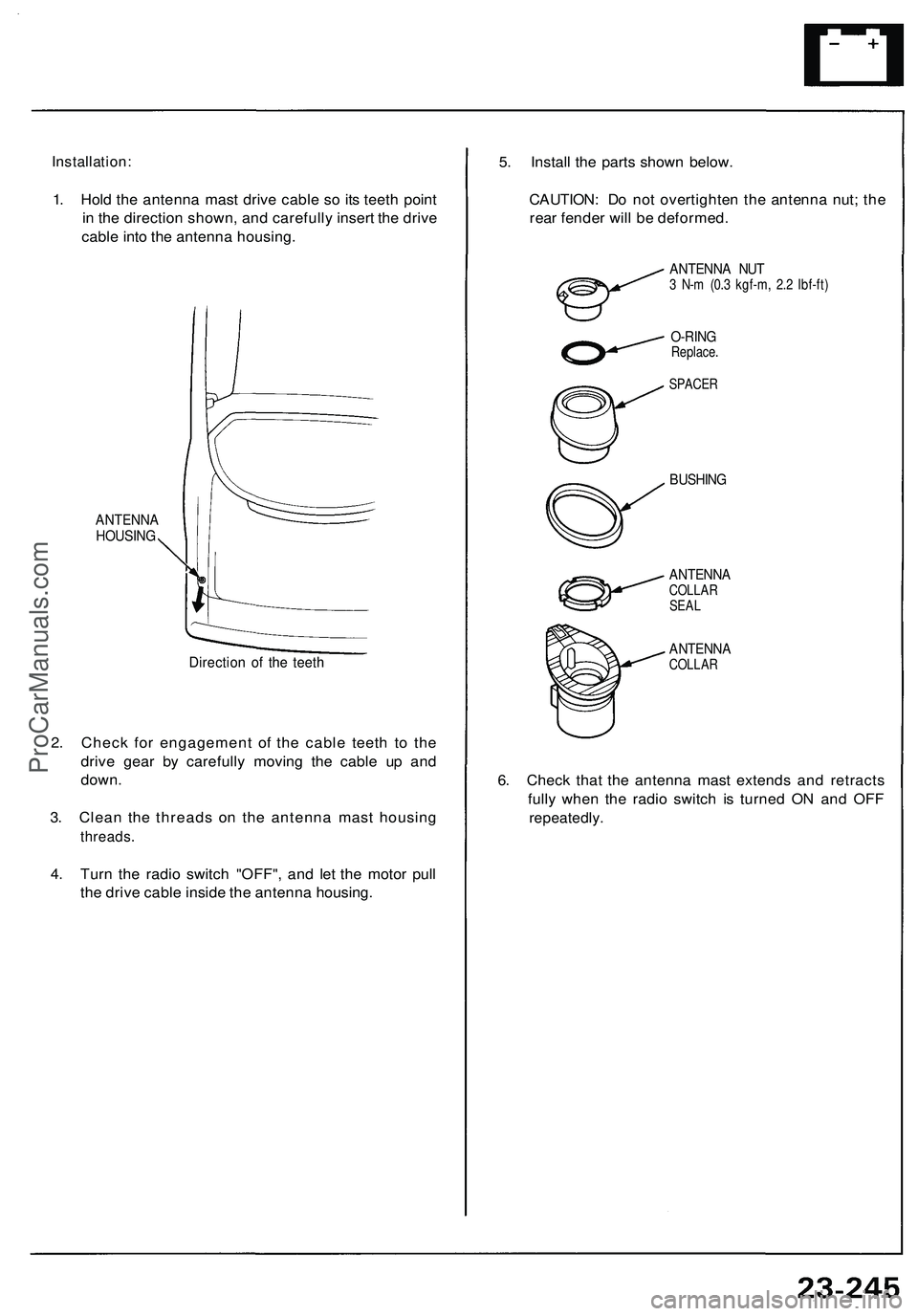
Installation:
1. Hold the antenna mast drive cable so its teeth point
in the direction shown, and carefully insert the drive
cable into the antenna housing.
ANTENNA
HOUSING
Direction of the teeth
2. Check for engagement of the cable teeth to the
drive gear by carefully moving the cable up and
down.
3. Clean the threads on the antenna mast housing
threads.
4. Turn the radio switch "OFF", and let the motor pull
the drive cable inside the antenna housing.
5. Install the parts shown below.
CAUTION: Do not overtighten the antenna nut; the
rear fender will be deformed.
ANTENNA NUT
3 N-m (0.3 kgf-m, 2.2 Ibf-ft)
O-RING
Replace.
SPACER
BUSHING
ANTENNA
COLLAR
SEAL
ANTENNA
COLLAR
6. Check that the antenna mast extends and retracts
fully when the radio switch is turned ON and OFF
repeatedly.ProCarManuals.com
Page 1390 of 1503
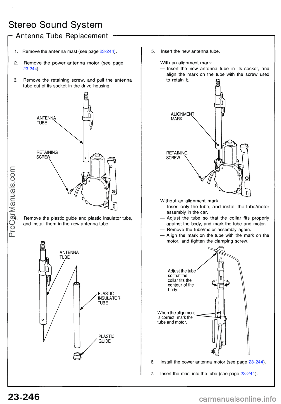
Stereo Soun d Syste m
Antenn a Tub e Replacemen t
1. Remov e th e antenn a mas t (se e pag e 23-244 ).
2 . Remov e th e powe r antenn a moto r (se e pag e
23-244).
3 . Remov e th e retainin g screw , an d pul l th e antenn a
tub e ou t o f it s socke t i n th e driv e housing .
ANTENN ATUBE
RETAININ GSCREW
4. Remov e th e plasti c guid e an d plasti c insulato r tube ,
an d instal l the m in th e ne w antenn a tube .
ANTENN ATUBE
PLASTIC
INSULATO RTUBE
PLASTI C
GUIDE
5. Inser t th e ne w antenn a tube .
With a n alignmen t mark :
— Inser t th e ne w antenn a tub e i n it s socket , an d
alig n th e mar k o n th e tub e wit h th e scre w use d
t o retai n it .
ALIGNMEN TMARK
RETAININ GSCREW
Withou t a n alignmen t mark :
— Inser t onl y th e tube , an d instal l th e tube/moto r
assembly i n th e car .
— Adjus t th e tub e s o tha t th e colla r fit s properl y
agains t th e body , an d mar k th e tub e an d motor .
— Remov e th e tube/moto r assembl y again .
— Alig n th e mar k o n th e tub e wit h th e mar k o n th e
motor , an d tighte n th e clampin g screw .
Adjust th e tub eso tha t th ecolla r fit s th econtou r o f th ebody .
When th e alignmen tis correct , mar k th etub e an d motor .
6. Instal l th e powe r antenn a moto r (se e pag e 23-244 ).
7 . Inser t th e mas t int o th e tub e (se e pag e 23-244 ).
ProCarManuals.com