CHEVROLET PLYMOUTH ACCLAIM 1993 Service Manual
PLYMOUTH ACCLAIM 1993
CHEVROLET
CHEVROLET
https://www.carmanualsonline.info/img/24/56861/w960_56861-0.png
CHEVROLET PLYMOUTH ACCLAIM 1993 Service Manual
Trending: maintenance, battery replacement, interior lights, run flat, wheel bolts, sensor, turn signal bulb
Page 2031 of 2438
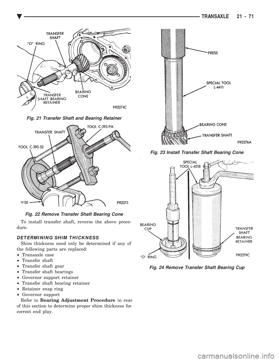
To install transfer shaft, reverse the above proce-
dure.
DETERMINING SHIM THICKNESS
Shim thickness need only be determined if any of
the following parts are replaced:
² Transaxle case
² Transfer shaft
² Transfer shaft gear
² Transfer shaft bearings
² Governor support retainer
² Transfer shaft bearing retainer
² Retainer snap ring
² Governor support
Refer to Bearing Adjustment Procedure in rear
of this section to determine proper shim thickness for
correct end play.
Fig. 23 Install Transfer Shaft Bearing Cone
Fig. 24 Remove Transfer Shaft Bearing Cup
Fig. 21 Transfer Shaft and Bearing Retainer
Fig. 22 Remove Transfer Shaft Bearing Cone
Ä TRANSAXLE 21 - 71
Page 2032 of 2438
PARKING PAWL
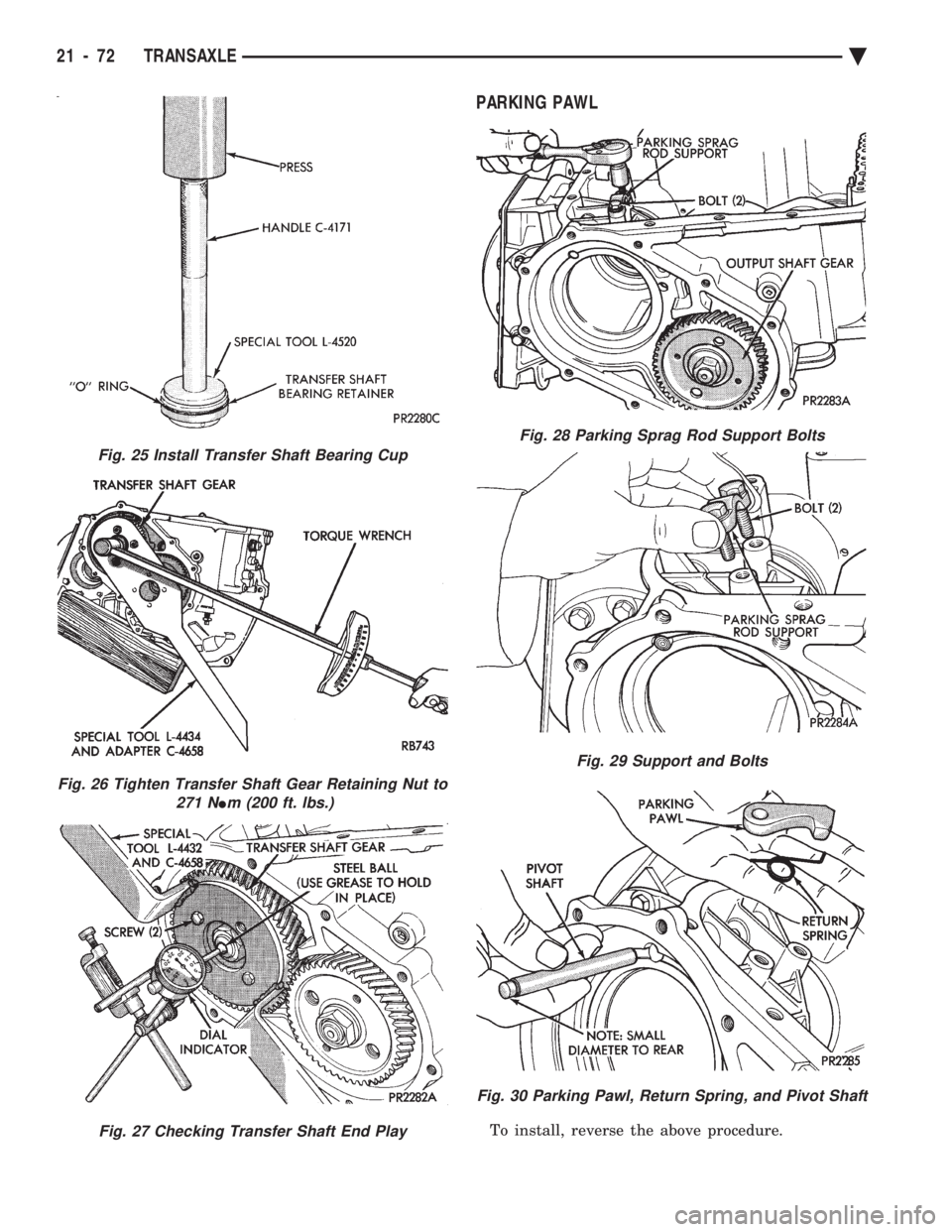
To install, reverse the above procedure.
Fig. 25 Install Transfer Shaft Bearing Cup
Fig. 26 Tighten Transfer Shaft Gear Retaining Nut to 271 N
Im (200 ft. lbs.)
Fig. 27 Checking Transfer Shaft End Play
Fig. 28 Parking Sprag Rod Support Bolts
Fig. 29 Support and Bolts
Fig. 30 Parking Pawl, Return Spring, and Pivot Shaft
21 - 72 TRANSAXLE Ä
Page 2033 of 2438
OUTPUT SHAFT REPAIR
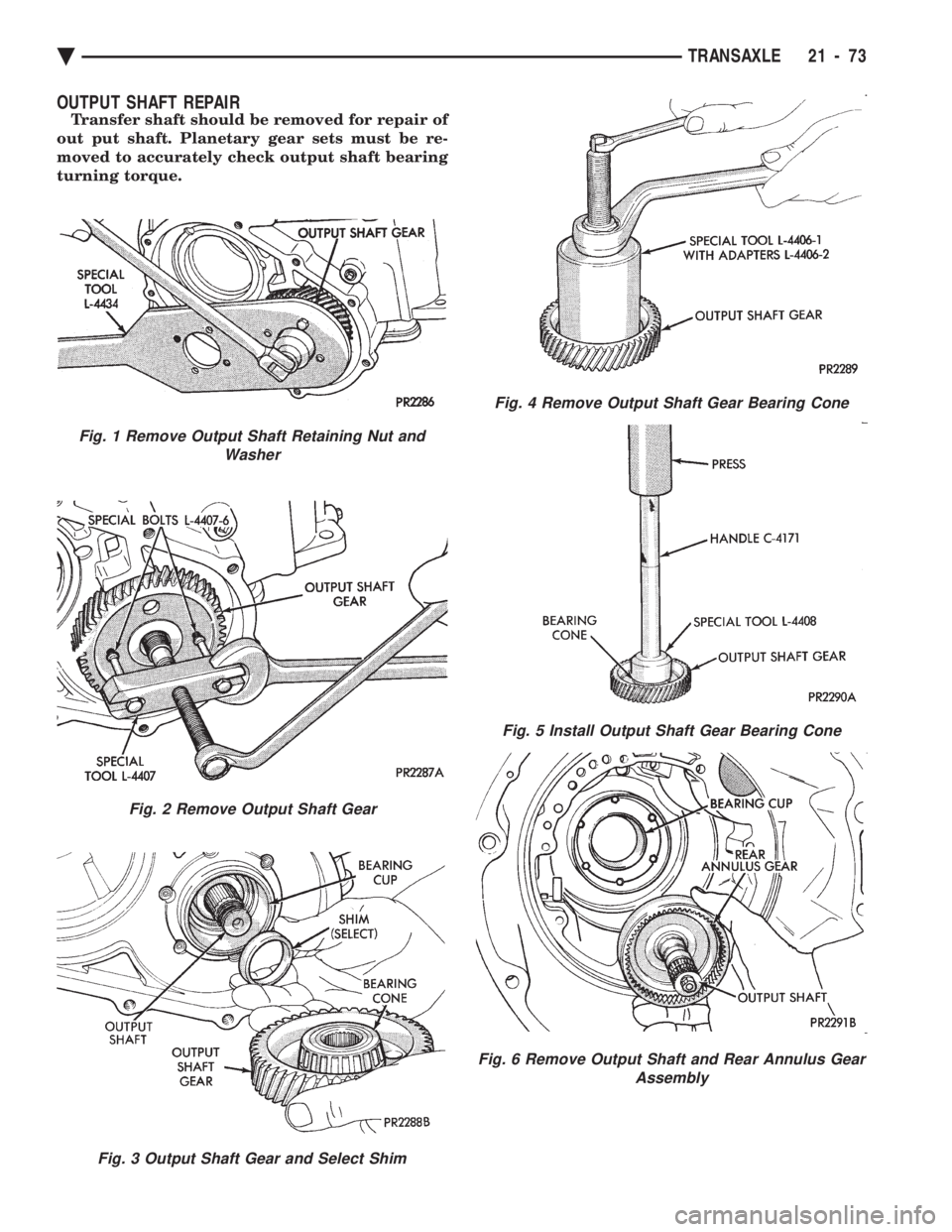
Transfer shaft should be removed for repair of
out put shaft. Planetary gear sets must be re-
moved to accurately check output shaft bearing
turning torque.
Fig. 1 Remove Output Shaft Retaining Nut and Washer
Fig. 2 Remove Output Shaft Gear
Fig. 3 Output Shaft Gear and Select Shim
Fig. 4 Remove Output Shaft Gear Bearing Cone
Fig. 5 Install Output Shaft Gear Bearing Cone
Fig. 6 Remove Output Shaft and Rear Annulus Gear Assembly
Ä TRANSAXLE 21 - 73
Page 2034 of 2438
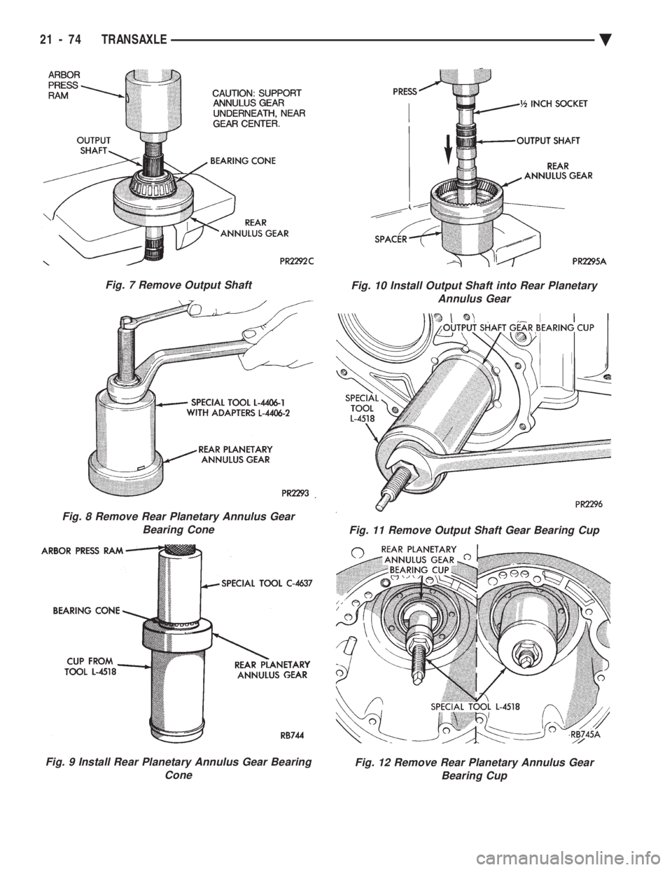
Fig. 7 Remove Output Shaft
Fig. 8 Remove Rear Planetary Annulus Gear Bearing Cone
Fig. 9 Install Rear Planetary Annulus Gear Bearing Cone
Fig. 10 Install Output Shaft into Rear PlanetaryAnnulus Gear
Fig. 11 Remove Output Shaft Gear Bearing Cup
Fig. 12 Remove Rear Planetary Annulus GearBearing Cup
21 - 74 TRANSAXLE Ä
Page 2035 of 2438
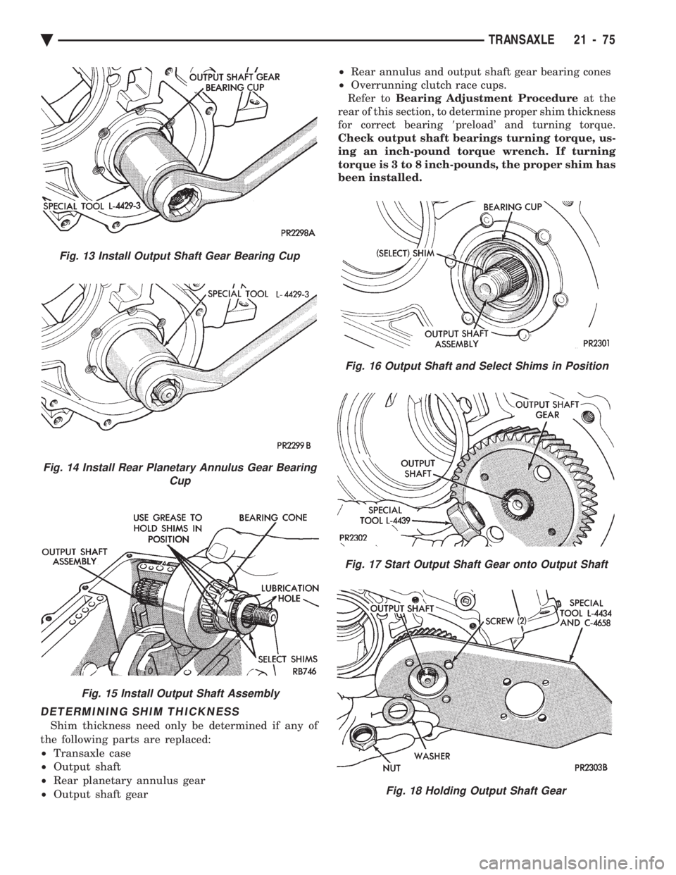
DETERMINING SHIM THICKNESS
Shim thickness need only be determined if any of
the following parts are replaced:
² Transaxle case
² Output shaft
² Rear planetary annulus gear
² Output shaft gear ²
Rear annulus and output shaft gear bearing cones
² Overrunning clutch race cups.
Refer to Bearing Adjustment Procedure at the
rear of this section, to determine proper shim thickness
for correct bearing 8preload' and turning torque.
Check output shaft bearings turning torque, us-
ing an inch-pound torque wrench. If turning
torque is 3 to 8 inch-pounds, the proper shim has
been installed.
Fig. 15 Install Output Shaft Assembly
Fig. 16 Output Shaft and Select Shims in Position
Fig. 17 Start Output Shaft Gear onto Output Shaft
Fig. 18 Holding Output Shaft Gear
Fig. 14 Install Rear Planetary Annulus Gear Bearing Cup
Fig. 13 Install Output Shaft Gear Bearing Cup
Ä TRANSAXLE 21 - 75
Page 2036 of 2438
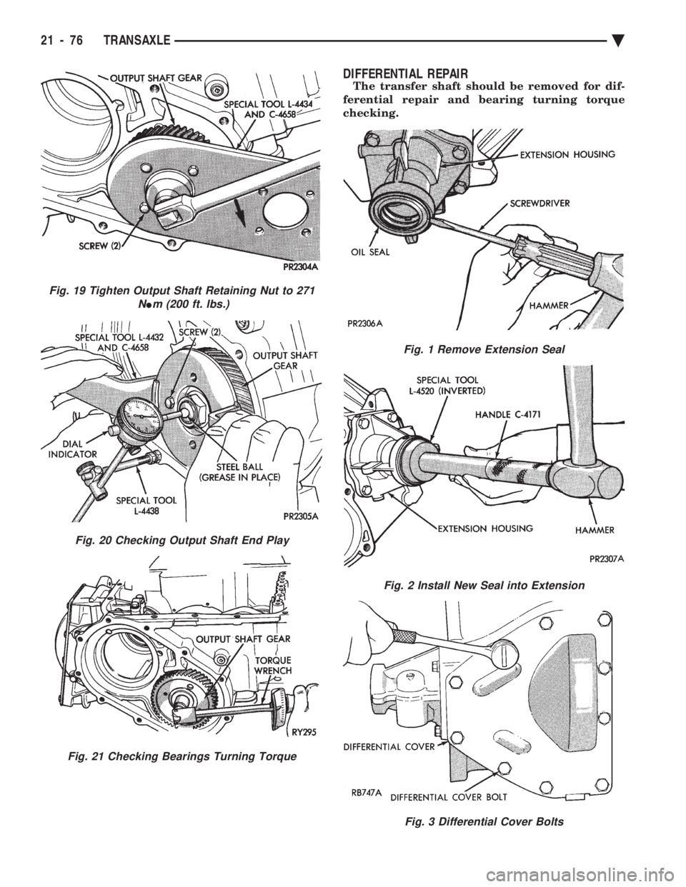
DIFFERENTIAL REPAIR
The transfer shaft should be removed for dif-
ferential repair and bearing turning torque
checking.
Fig. 19 Tighten Output Shaft Retaining Nut to 271 N
Im (200 ft. lbs.)
Fig. 20 Checking Output Shaft End Play
Fig. 21 Checking Bearings Turning Torque
Fig. 1 Remove Extension Seal
Fig. 2 Install New Seal into Extension
Fig. 3 Differential Cover Bolts
21 - 76 TRANSAXLE Ä
Page 2037 of 2438
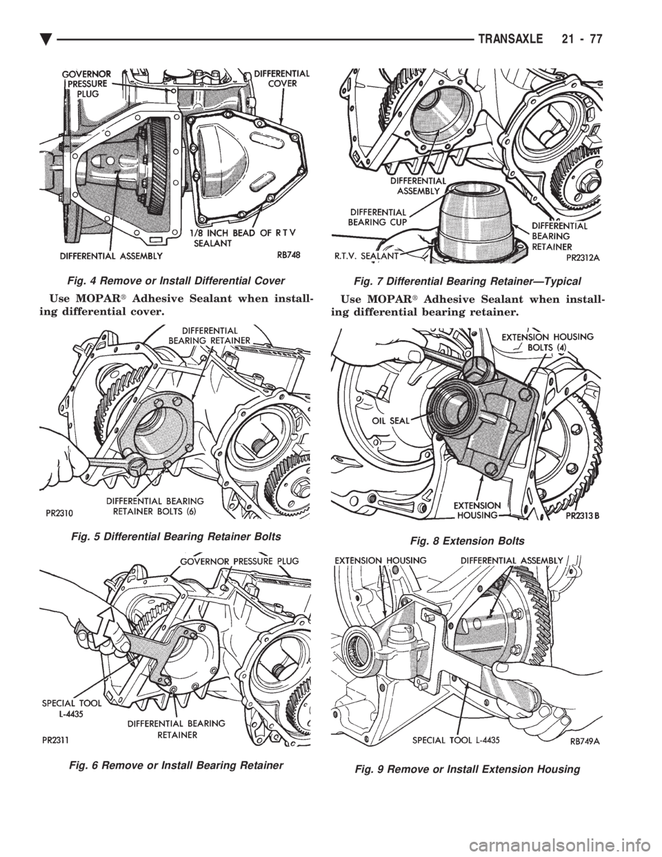
Use MOPAR tAdhesive Sealant when install-
ing differential cover. Use MOPAR
tAdhesive Sealant when install-
ing differential bearing retainer.
Fig. 4 Remove or Install Differential Cover
Fig. 5 Differential Bearing Retainer Bolts
Fig. 6 Remove or Install Bearing Retainer
Fig. 7 Differential Bearing RetainerÐTypical
Fig. 8 Extension Bolts
Fig. 9 Remove or Install Extension Housing
Ä TRANSAXLE 21 - 77
Page 2038 of 2438
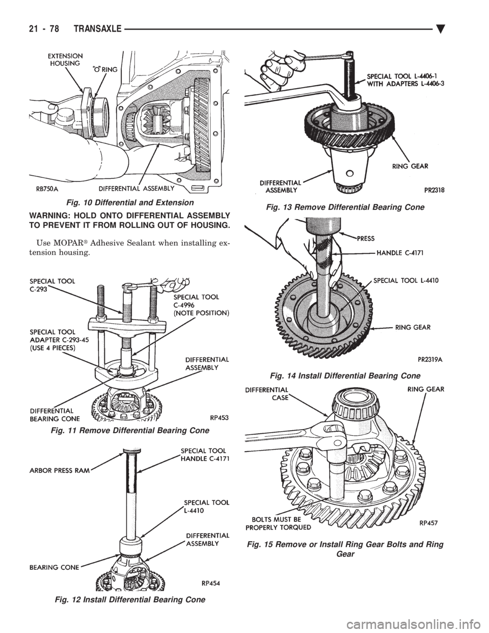
WARNING: HOLD ONTO DIFFERENTIAL ASSEMBLY
TO PREVENT IT FROM ROLLING OUT OF HOUSING.
Use MOPAR tAdhesive Sealant when installing ex-
tension housing.
Fig. 10 Differential and Extension
Fig. 11 Remove Differential Bearing Cone
Fig. 12 Install Differential Bearing Cone
Fig. 13 Remove Differential Bearing Cone
Fig. 14 Install Differential Bearing Cone
Fig. 15 Remove or Install Ring Gear Bolts and Ring Gear
21 - 78 TRANSAXLE Ä
Page 2039 of 2438
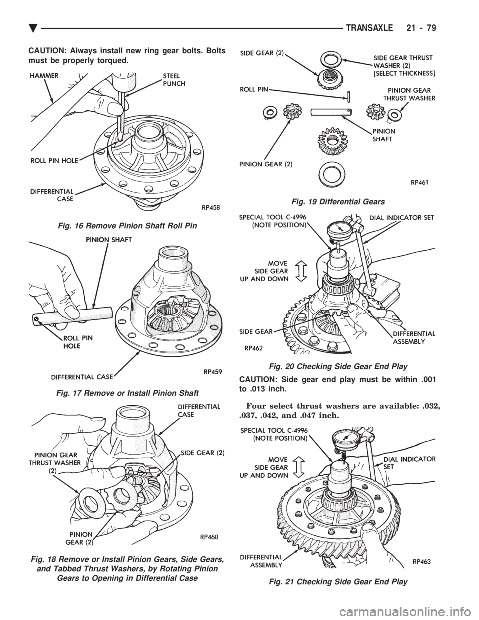
CAUTION: Always install new ring gear bolts. Bolts
must be properly torqued. CAUTION: Side gear end play must be within .001
to .013 inch.
Four select thrust washers are available: .032,
.037, .042, and .047 inch.
Fig. 16 Remove Pinion Shaft Roll Pin
Fig. 17 Remove or Install Pinion Shaft
Fig. 18 Remove or Install Pinion Gears, Side Gears, and Tabbed Thrust Washers, by Rotating Pinion Gears to Opening in Differential Case
Fig. 19 Differential Gears
Fig. 20 Checking Side Gear End Play
Fig. 21 Checking Side Gear End Play
Ä TRANSAXLE 21 - 79
Page 2040 of 2438
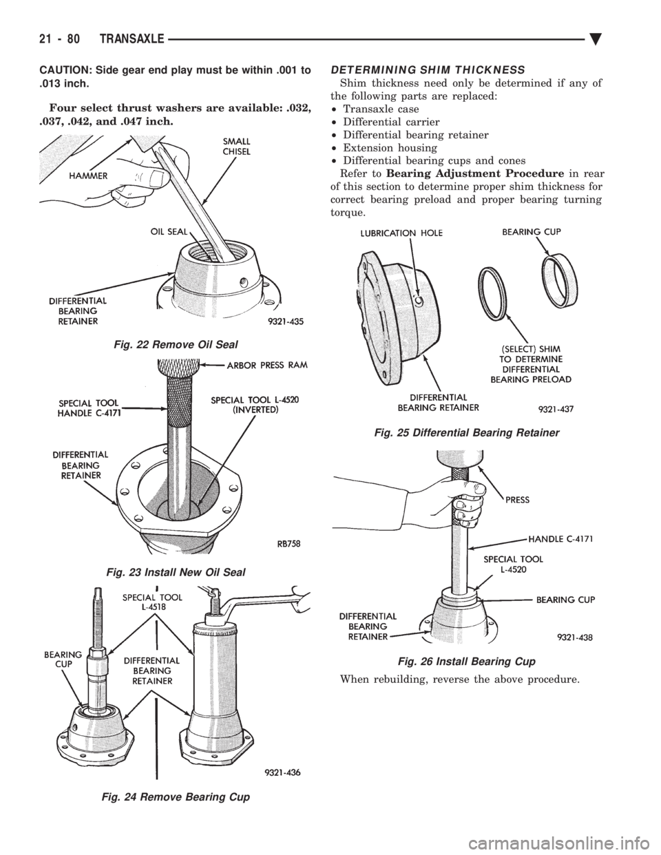
CAUTION: Side gear end play must be within .001 to
.013 inch. Four select thrust washers are available: .032,
.037, .042, and .047 inch.DETERMINING SHIM THICKNESS
Shim thickness need only be determined if any of
the following parts are replaced:
² Transaxle case
² Differential carrier
² Differential bearing retainer
² Extension housing
² Differential bearing cups and cones
Refer to Bearing Adjustment Procedure in rear
of this section to determine proper shim thickness for
correct bearing preload and proper bearing turning
torque.
When rebuilding, reverse the above procedure.
Fig. 25 Differential Bearing Retainer
Fig. 26 Install Bearing Cup
Fig. 22 Remove Oil Seal
Fig. 23 Install New Oil Seal
Fig. 24 Remove Bearing Cup
21 - 80 TRANSAXLE Ä
Trending: fascia, clock setting, engine oil capacity, wiper fluid, air bleeding, oil type, width
