DODGE RAM 2001 Service Repair Manual
Manufacturer: DODGE, Model Year: 2001, Model line: RAM, Model: DODGE RAM 2001Pages: 2889, PDF Size: 68.07 MB
Page 1481 of 2889
FRAME
DESCRIPTION
The BR/BE frame is the structural center of the
vehicle. In addition to supporting the body and pay-
load, the frame provides a station for the engine and
drivetrain. BR/BE trucks have a ladder type frame
with Box-section front rails, dropped center section,
and open-channel side rails in the rear.
Cross members attach to the side rails with rivets,
welds, or bolts. The cab is isolated from the frame
with rubber load cushions with through bolts. The
cargo box or bed is attached to the frame with bolts.
The frame is designed to absorb and dissipate flex-
ing and twisting due to acceleration, braking, corner-
ing, and road surface variances without bending
when subjected to normal driving conditions.
FRAME SERVICE
SAFETY PRECAUTIONS AND WARNINGS
WARNING: USE EYE PROTECTION WHEN GRIND-
ING OR WELDING METAL, SERIOUS EYE INJURY
CAN RESULT. BEFORE PROCEEDING WITH FRAME
REPAIR INVOLVING GRINDING OR WELDING, VER-
IFY THAT VEHICLE FUEL SYSTEM IS NOT LEAKING
OR IN CONTACT WITH REPAIR AREA, PERSONAL
INJURY CAN RESULT. DO NOT ALLOW OPEN
FLAME TO CONTACT PLASTIC BODY PANELS.
FIRE OR EXPLOSION CAN RESULT. WHEN
WELDED FRAME COMPONENTS ARE REPLACED,
100% PENETRATION WELD MUST BE ACHIEVED
DURING INSTALLATION. IF NOT, DANGEROUS
OPERATING CONDITIONS CAN RESULT. STAND
CLEAR OF CABLES OR CHAINS ON PULLING
EQUIPMENT DURING FRAME STRAIGHTENING
OPERATIONS, PERSONAL INJURY CAN RESULT.
DO NOT VENTURE UNDER A HOISTED VEHICLE
THAT IS NOT SUPPORTED ON SAFETY STANDS,
PERSONAL INJURY CAN RESULT.
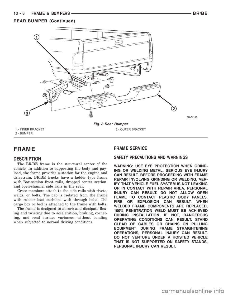
Fig. 8 Rear Bumper
1 - INNER BRACKET
2 - BUMPER3 - OUTER BRACKET
13 - 6 FRAME & BUMPERSBR/BE
REAR BUMPER (Continued)
Page 1482 of 2889
CAUTION: Do not reuse damaged fasteners, quality
of repair would be suspect. Do not drill holes in top
or bottom frame rail flanges, frame rail failure can
result. Do Not use softer than Grade 5 bolts to
replace production fasteners, loosening or failure
can result. When using heat to straighten frame
components do not exceed 566ÉC (1050ÉF), metal
fatigue can result. Welding the joints around riveted
cross members and frame side rails can weaken
frame.
FRAME STRAIGHTENING
When necessary, a conventional frame that is bent
or twisted can be straightened by application of heat.
The temperature must not exceed 566ÉC (1050ÉF).
The metal will have a dull red glow at the desired
temperature. Excessive heat will decrease the
strength of the metal and result in a weakened
frame.
Welding the joints around riveted cross members
and frame side rails is not recommended.
A straightening repair process should be limited to
frame members that are not severely damaged. The
replacement bolts, nuts and rivets that are used to
join the frame members should conform to the same
specifications as the original bolts, nuts and rivets.
FRAME REPAIRS
DRILLING HOLES
Do not drill holes in frame side rail top and bottom
flanges, metal fatigue can result causing frame fail-
ure. Holes drilled in the side of the frame rail must
be at least 38 mm (1.5 in.) from the top and bottom
flanges.
Additional drill holes should be located away from
existing holes.
WELDING
Use MIG, TIG or arc welding equipment to repair
welded frame components.
Frame components that have been damaged should
be inspected for cracks before returning the vehicle
to use. If cracks are found in accessible frame com-
ponents perform the following procedures.
(1) Drill a hole at each end of the crack with a 3
mm (O.125 in.) diameter drill bit.
(2) Using a suitable die grinder with 3 inch cut off
wheel, V-groove the crack to allow 100% weld pene-
tration.
(3) Weld the crack.(4) If necessary when a side rail is repaired, grind
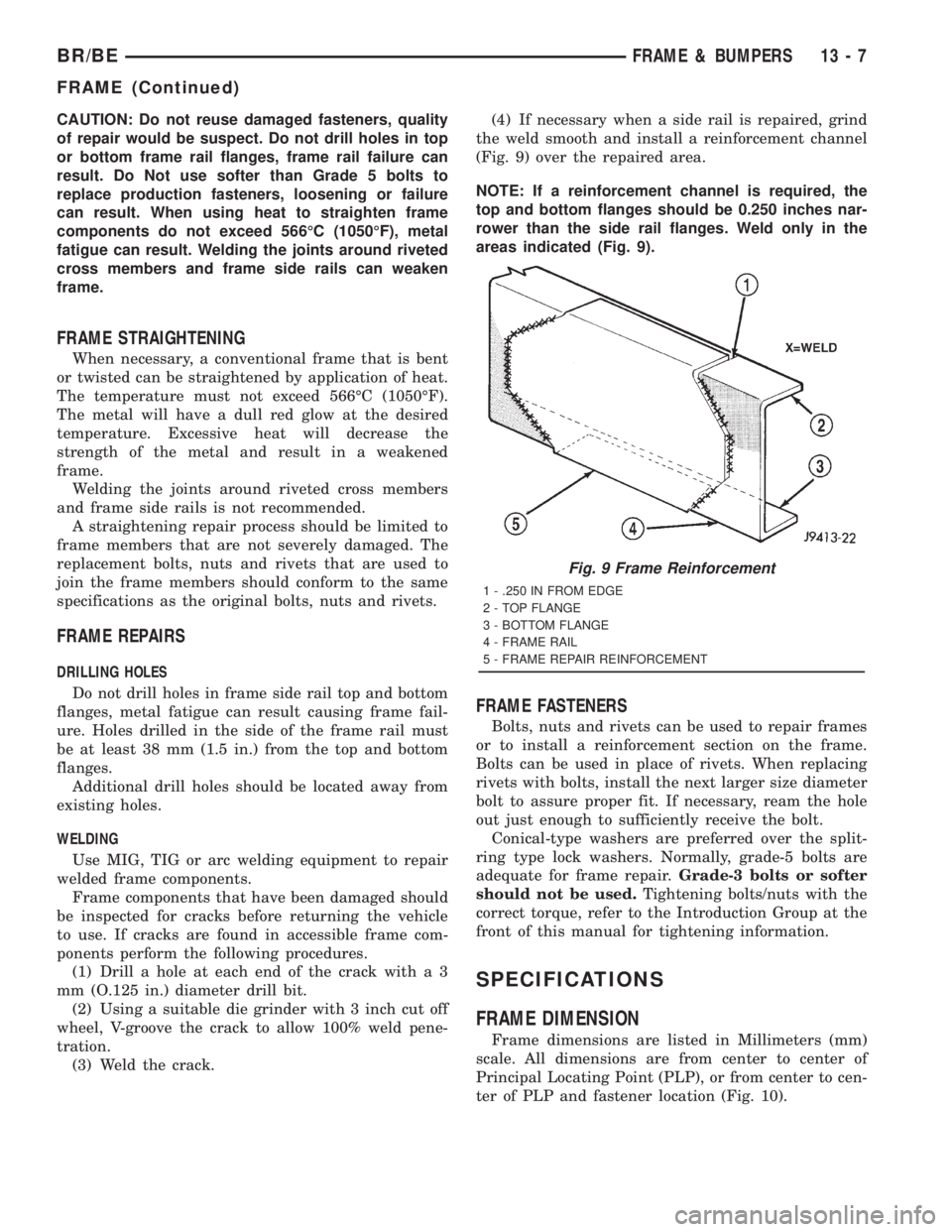
the weld smooth and install a reinforcement channel
(Fig. 9) over the repaired area.
NOTE: If a reinforcement channel is required, the
top and bottom flanges should be 0.250 inches nar-
rower than the side rail flanges. Weld only in the
areas indicated (Fig. 9).
FRAME FASTENERS
Bolts, nuts and rivets can be used to repair frames
or to install a reinforcement section on the frame.
Bolts can be used in place of rivets. When replacing
rivets with bolts, install the next larger size diameter
bolt to assure proper fit. If necessary, ream the hole
out just enough to sufficiently receive the bolt.
Conical-type washers are preferred over the split-
ring type lock washers. Normally, grade-5 bolts are
adequate for frame repair.Grade-3 bolts or softer
should not be used.Tightening bolts/nuts with the
correct torque, refer to the Introduction Group at the
front of this manual for tightening information.
SPECIFICATIONS
FRAME DIMENSION
Frame dimensions are listed in Millimeters (mm)
scale. All dimensions are from center to center of
Principal Locating Point (PLP), or from center to cen-
ter of PLP and fastener location (Fig. 10).
Fig. 9 Frame Reinforcement
1 - .250 IN FROM EDGE
2 - TOP FLANGE
3 - BOTTOM FLANGE
4 - FRAME RAIL
5 - FRAME REPAIR REINFORCEMENT
BR/BEFRAME & BUMPERS 13 - 7
FRAME (Continued)
Page 1483 of 2889
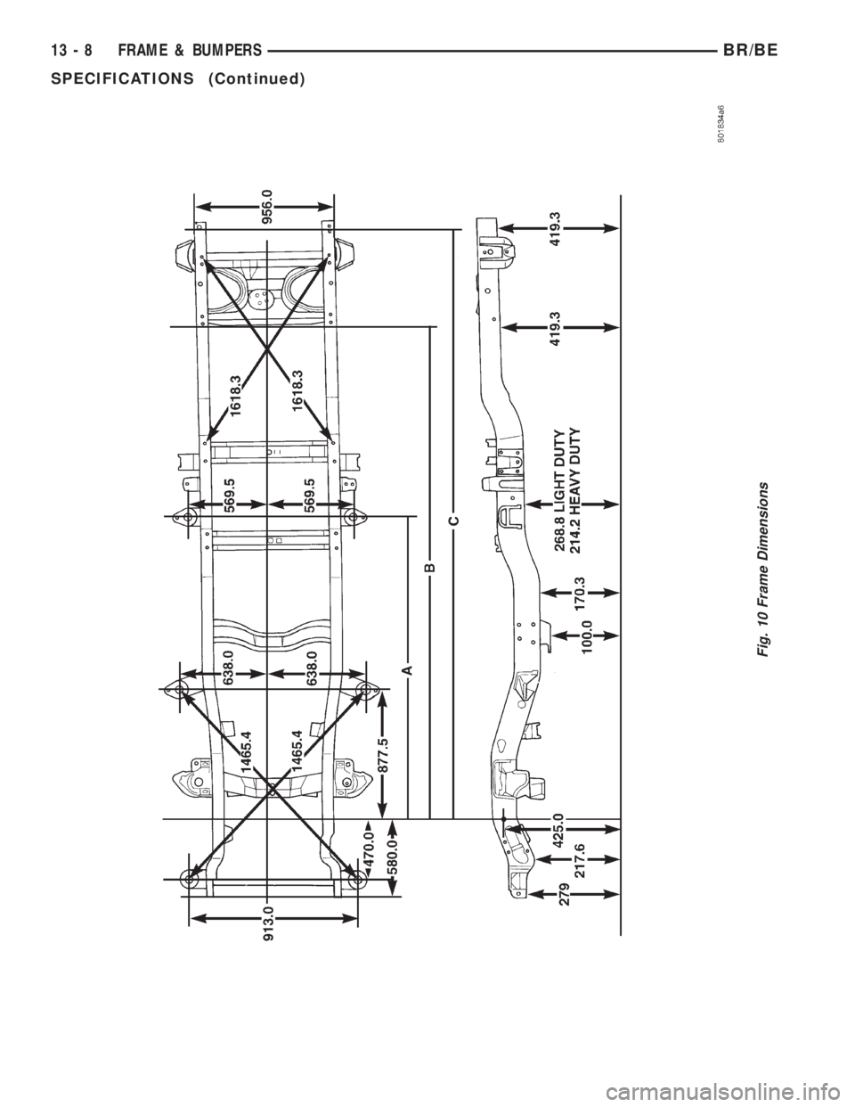
Fig. 10 Frame Dimensions
13 - 8 FRAME & BUMPERSBR/BE
SPECIFICATIONS (Continued)
Page 1484 of 2889
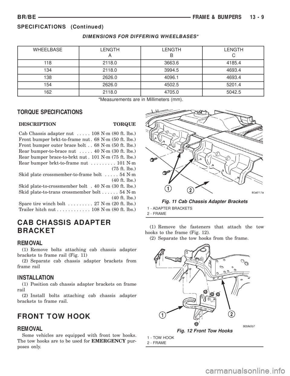
DIMENSIONS FOR DIFFERING WHEELBASES*
WHEELBASE LENGTH
ALENGTH
BLENGTH
C
118 2118.0 3663.6 4185.4
134 2118.0 3994.5 4693.4
138 2626.0 4096.1 4693.4
154 2626.0 4502.5 5201.4
162 2118.0 4705.0 5042.5
*Measurements are in Millimeters (mm).
TORQUE SPECIFICATIONS
DESCRIPTION TORQUE
Cab Chassis adapter nut..... 108N´m(80ft.lbs.)
Front bumper brkt-to-frame nut . 68 N´m (50 ft. lbs.)
Front bumper outer brace bolt . . 68 N´m (50 ft. lbs.)
Rear bumper-to-brace nut..... 40N´m(30ft.lbs.)
Rear bumper brace-to-brkt nut . 101 N´m (75 ft. lbs.)
Rear bumper brkt-to-frame nut......... 101N´m
(75 ft. lbs.)
Skid plate crossmember-to-frame bolt..... 54N´m
(40 ft. lbs.)
Skid plate-to-crossmember bolt . 40 N´m (30 ft. lbs.)
Skid plate-to-trans crossmember bolt...... 54N´m
(40 ft. lbs.)
Spare tire winch bolt......... 27N´m(20ft.lbs.)
Trailer hitch nut............ 108N´m(80ft.lbs.)
CAB CHASSIS ADAPTER
BRACKET
REMOVAL
(1) Remove bolts attaching cab chassis adapter
brackets to frame rail (Fig. 11)
(2) Separate cab chassis adapter brackets from
frame rail
INSTALLATION
(1) Position cab chassis adapter brackets on frame
rail
(2) Install bolts attaching cab chassis adapter
brackets to frame rail.
FRONT TOW HOOK
REMOVAL
Some vehicles are equipped with front tow hooks.
The tow hooks are to be used forEMERGENCYpur-
poses only.(1) Remove the fasteners that attach the tow
hooks to the frame (Fig. 12).
(2) Separate the tow hooks from the frame.
Fig. 11 Cab Chassis Adapter Brackets
1 - ADAPTER BRACKETS
2 - FRAME
Fig. 12 Front Tow Hooks
1 - TOW HOOK
2 - FRAME
BR/BEFRAME & BUMPERS 13 - 9
SPECIFICATIONS (Continued)
Page 1485 of 2889
Installation
Some vehicles are equipped with front tow hooks.
The tow hooks are to be used forEMERGENCYpur-
poses only.
(1) Position the tow hooks on the frame.
(2) Install the fasteners that attach the tow hooks
to the frame.
(3) Tighten the nuts to 108 N´m (80 ft. lbs.) torque.
SPARE TIRE WINCH
REMOVAL
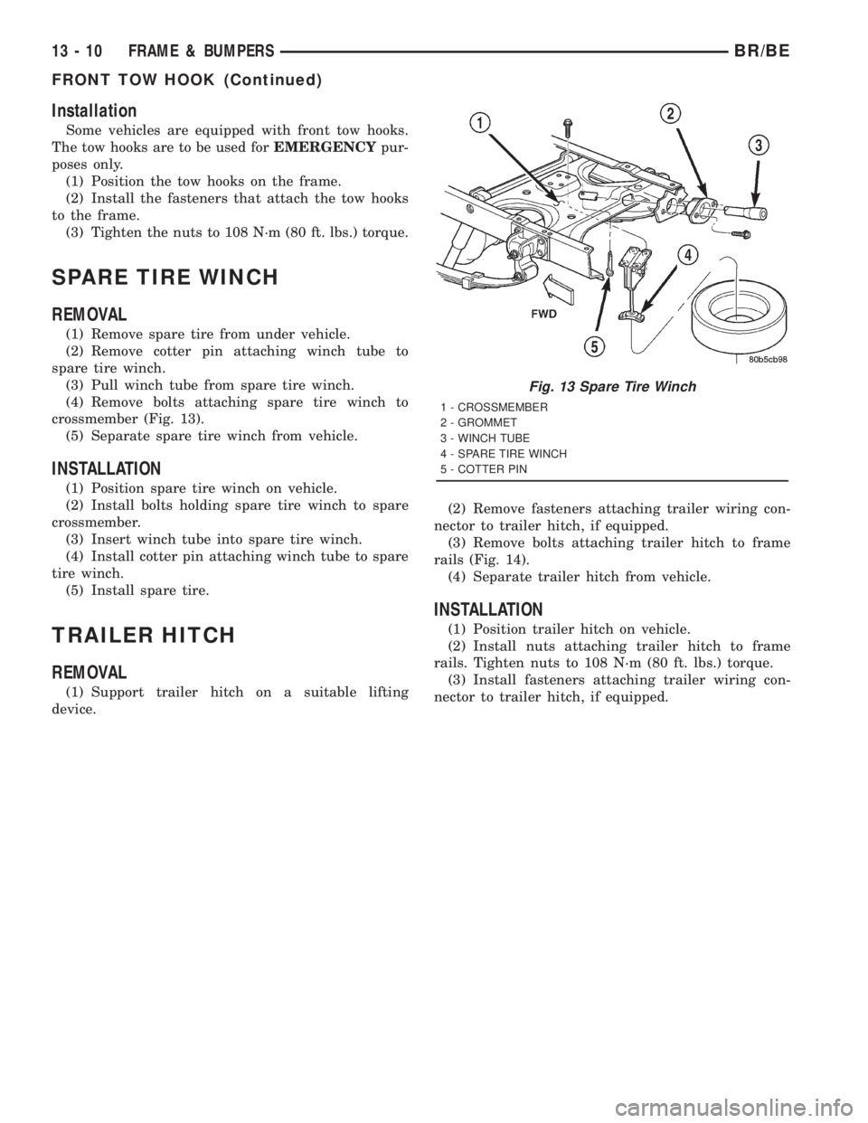
(1) Remove spare tire from under vehicle.
(2) Remove cotter pin attaching winch tube to
spare tire winch.
(3) Pull winch tube from spare tire winch.
(4) Remove bolts attaching spare tire winch to
crossmember (Fig. 13).
(5) Separate spare tire winch from vehicle.
INSTALLATION
(1) Position spare tire winch on vehicle.
(2) Install bolts holding spare tire winch to spare
crossmember.
(3) Insert winch tube into spare tire winch.
(4) Install cotter pin attaching winch tube to spare
tire winch.
(5) Install spare tire.
TRAILER HITCH
REMOVAL
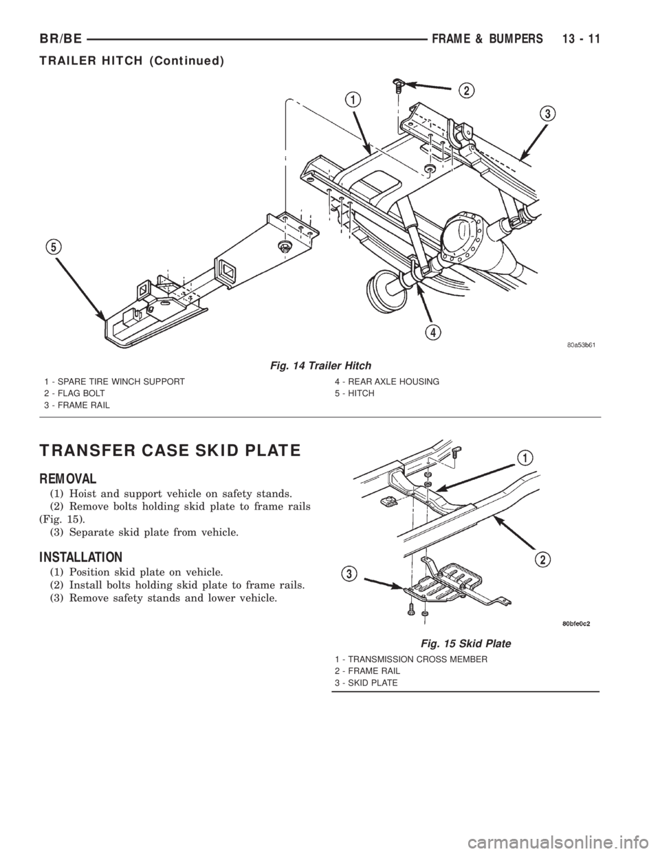
(1) Support trailer hitch on a suitable lifting
device.(2) Remove fasteners attaching trailer wiring con-
nector to trailer hitch, if equipped.
(3) Remove bolts attaching trailer hitch to frame
rails (Fig. 14).
(4) Separate trailer hitch from vehicle.
INSTALLATION
(1) Position trailer hitch on vehicle.
(2) Install nuts attaching trailer hitch to frame
rails. Tighten nuts to 108 N´m (80 ft. lbs.) torque.
(3) Install fasteners attaching trailer wiring con-
nector to trailer hitch, if equipped.
Fig. 13 Spare Tire Winch
1 - CROSSMEMBER
2 - GROMMET
3 - WINCH TUBE
4 - SPARE TIRE WINCH
5 - COTTER PIN
13 - 10 FRAME & BUMPERSBR/BE
FRONT TOW HOOK (Continued)
Page 1486 of 2889
TRANSFER CASE SKID PLATE
REMOVAL
(1) Hoist and support vehicle on safety stands.
(2) Remove bolts holding skid plate to frame rails
(Fig. 15).
(3) Separate skid plate from vehicle.
INSTALLATION
(1) Position skid plate on vehicle.
(2) Install bolts holding skid plate to frame rails.
(3) Remove safety stands and lower vehicle.
Fig. 14 Trailer Hitch
1 - SPARE TIRE WINCH SUPPORT
2 - FLAG BOLT
3 - FRAME RAIL4 - REAR AXLE HOUSING
5 - HITCH
Fig. 15 Skid Plate
1 - TRANSMISSION CROSS MEMBER
2 - FRAME RAIL
3 - SKID PLATE
BR/BEFRAME & BUMPERS 13 - 11
TRAILER HITCH (Continued)
Page 1487 of 2889

Page 1488 of 2889
FUEL SYSTEM
TABLE OF CONTENTS
page page
FUEL DELIVERY - GASOLINE................1
FUEL INJECTION - GASOLINE..............28FUEL DELIVERY - DIESEL.................54
FUEL INJECTION - DIESEL.................87
FUEL DELIVERY - GASOLINE
TABLE OF CONTENTS
page page
FUEL DELIVERY - GASOLINE
DESCRIPTION............................2
OPERATION.............................2
DIAGNOSIS AND TESTING..................2
FUEL PRESSURE LEAK DOWN TEST........2
STANDARD PROCEDURE...................3
FUEL SYSTEM PRESSURE RELEASE
PROCEDURE...........................3
SPECIFICATIONS.........................4
SPECIAL TOOLS..........................4
FUEL FILTER/PRESSURE REGULATOR
DESCRIPTION............................5
OPERATION.............................5
REMOVAL...............................5
INSTALLATION............................6
FUEL LEVEL SENDING UNIT / SENSOR
DESCRIPTION............................7
OPERATION.............................7
DIAGNOSIS AND TESTING..................8
FUEL GAUGE SENDING UNIT..............8
REMOVAL...............................8
INSTALLATION............................9
FUEL LINES
DESCRIPTION............................9
FUEL PUMP
DESCRIPTION............................9
OPERATION.............................9
DIAGNOSIS AND TESTING..................9
FUEL PUMP CAPACITY TEST..............9FUEL PUMP PRESSURE TEST............10
FUEL PUMP AMPERAGE TEST............10
FUEL PUMP MODULE
DESCRIPTION...........................12
OPERATION.............................13
REMOVAL..............................13
INSTALLATION...........................13
FUEL RAIL
DESCRIPTION...........................15
OPERATION.............................15
REMOVAL..............................16
INSTALLATION...........................18
FUEL TANK
DESCRIPTION...........................19
OPERATION.............................19
REMOVAL..............................19
INSTALLATION...........................20
INLET FILTER
REMOVAL..............................22
INSTALLATION...........................22
QUICK CONNECT FITTING
DESCRIPTION...........................22
STANDARD PROCEDURE..................22
QUICK-CONNECT FITTINGS..............22
ROLLOVER VALVE
DESCRIPTION...........................25
REMOVAL..............................26
INSTALLATION...........................27
BR/BEFUEL SYSTEM 14 - 1
Page 1489 of 2889
FUEL DELIVERY - GASOLINE
DESCRIPTION - FUEL DELIVERY SYSTEM
The fuel delivery system consists of:
²the fuel pump module containing the electric
fuel pump, fuel filter/fuel pressure regulator, rollover
valve (certain modules), fuel gauge sending unit (fuel
level sensor) and a separate fuel filter located at bot-
tom of pump module
²fuel tubes/lines/hoses
²quick-connect fittings
²fuel injector rail
²fuel injectors
²fuel tank
²fuel tank filler/vent tube assembly
²fuel tank filler tube cap
²accelerator pedal
²throttle cable
OPERATION - FUEL DELIVERY SYSTEM
Fuel is returned through the fuel pump module
and back into the fuel tank through the fuel filter/
fuel pressure regulator. A separate fuel return line
from the engine to the tank is not used with any gas-
oline powered engine.
The fuel tank assembly consists of: the fuel tank,
fuel pump module assembly, fuel pump module lock-
nut/gasket and rollover valve(s) (refer to 25, Emis-
sion Control System for rollover valve information).
A fuel filler/vent tube assembly using a pressure/
vacuum, 1/4 turn fuel filler cap is used. The fuel
filler tube contains a flap door located below the fuel
fill cap.
Also to be considered part of the fuel system is the
evaporation control system. This is designed to
reduce the emission of fuel vapors into the atmo-
sphere. The description and function of the Evapora-
tive Control System is found in 25, Emission Control
Systems.
Both fuel filters (at bottom of fuel pump module
and within fuel pressure regulator) are designed for
extended service. They do not require normal sched-
uled maintenance. Filters should only be replaced if
a diagnostic procedure indicates to do so.
DIAGNOSIS AND TESTING - FUEL PRESSURE
LEAK DOWN TEST
Use this test in conjunction with the Fuel Pump
Pressure Test and Fuel Pump Capacity Test.
Check Valve Operation:The electric fuel pump
outlet contains a one-way check valve to prevent fuel
flow back into the tank and to maintain fuel supply
line pressure (engine warm) when pump is not oper-
ational. It is also used to keep the fuel supply line
full of gasoline when pump is not operational. Afterthe vehicle has cooled down, fuel pressure may drop
to 0 psi (cold fluid contracts), but liquid gasoline will
remain in fuel supply line between the check valve
and fuel injectors.Fuel pressure that has
dropped to 0 psi on a cooled down vehicle
(engine off) is a normal condition.When the elec-
tric fuel pump is activated, fuel pressure should
immediately(1±2 seconds) rise to specification.
Abnormally long periods of cranking to restart a
hotengine that has been shut down for a short
period of time may be caused by:
²Fuel pressure bleeding past a fuel injector(s).
²Fuel pressure bleeding past the check valve in
the fuel pump module.
(1) Disconnect the fuel inlet line at fuel rail. Refer
to Fuel Tubes/Lines/Hoses and Clamps for proce-
dures. On some engines, air cleaner housing removal
may be necessary before fuel line disconnection.
(2) Obtain correct Fuel Line Pressure Test Adapter
Tool Hose. Tool number 6539 is used for 5/16º fuel
lines and tool number 6631 is used for 3/8º fuel lines.
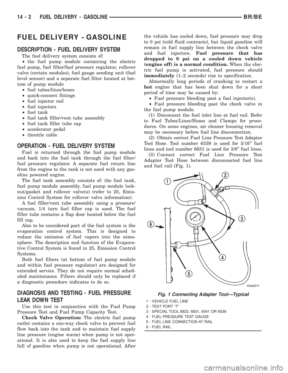
(3) Connect correct Fuel Line Pressure Test
Adapter Tool Hose between disconnected fuel line
and fuel rail (Fig. 1).
Fig. 1 Connecting Adapter ToolÐTypical
1 - VEHICLE FUEL LINE
2 - TEST PORT ªTº
3 - SPECIAL TOOL 6923, 6631, 6541 OR 6539
4 - FUEL PRESSURE TEST GAUGE
5 - FUEL LINE CONNECTION AT RAIL
6 - FUEL RAIL
14 - 2 FUEL DELIVERY - GASOLINEBR/BE
Page 1490 of 2889
(4) Connect the 0-414 kPa (0-60 psi) fuel pressure
test gauge (from Gauge Set 5069) to the test port on
the appropriate Adaptor Tool.The DRBtIII Scan
Tool along with the PEP module, the 500 psi
pressure transducer, and the transducer-to-test
port adapter may also be used in place of the
fuel pressure gauge.
The fittings on both tools must be in good
condition and free from any small leaks before
performing the proceeding test.
(5) Start engine and bring to normal operating
temperature.
(6) Observe test gauge. Normal operating pressure
should be 339 kPa +/±34 kPa (49.2 psi +/±5 psi).
(7) Shut engine off.
(8) Pressure should not fall below30 psi for five
minutes.
(9) If pressure falls below 30 psi, it must be deter-
mined if a fuel injector, the check valve within the
fuel pump module, or a fuel tube/line is leaking.
(10) Again, start engine and bring to normal oper-
ating temperature.
(11) Shut engine off.
(12)Testing for fuel injector or fuel rail leak-
age:Clamp off the rubber hose portion of Adaptor
Tool between the fuel rail and the test port ªTº on
Adapter Tool. If pressure now holds at or above 30
psi, a fuel injector or the fuel rail is leaking.
(13)Testing for fuel pump check valve, filter/
regulator check valve or fuel tube/line leakage:
Clamp off the rubber hose portion of Adaptor Tool
between the vehicle fuel line and test port ªTº on
Adapter Tool. If pressure now holds at or above 30
psi, a leak may be found at a fuel tube/line. If no
leaks are found at fuel tubes or lines, one of the
check valves in either the electric fuel pump or filter/
regulator may be leaking.
Note: A quick loss of pressure usually indicates a
defective check valve in the filter/regulator. A slow
loss of pressure usually indicates a defective check
valve in the electric fuel pump.
The electric fuel pump is not serviced separately.
Replace the fuel pump module assembly. The filter/
regulator may be replaced separately on certain
applications. Refer to Fuel Filter/Fuel Pressure Reg-
ulator Removal/Installation for additional informa-
tion.STANDARD PROCEDURE - FUEL SYSTEM
PRESSURE RELEASE
Use following procedure if the fuel injector
rail is, or is not equipped with a fuel pressure
test port.
(1) Remove fuel fill cap.
(2) Remove fuel pump relay from Power Distribu-
tion Center (PDC). For location of relay, refer to label
on underside of PDC cover.
(3) Start and run engine until it stalls.
(4) Attempt restarting engine until it will no
longer run.
(5) Turn ignition key to OFF position.
CAUTION: Steps 1, 2, 3 and 4 must be performed to
relieve high pressure fuel from within fuel rail. Do
not attempt to use following steps to relieve this
pressure as excessive fuel will be forced into a cyl-
inder chamber.
(6) Unplug connector from any fuel injector.
(7) Attach one end of a jumper wire with alligator
clips (18 gauge or smaller) to either injector terminal.
(8) Connect other end of jumper wire to positive
side of battery.
(9) Connect one end of a second jumper wire to
remaining injector terminal.
CAUTION: Powering an injector for more than a few
seconds will permanently damage the injector.
(10) Momentarily touch other end of jumper wire
to negative terminal of battery for no more than a
few seconds.
(11) Place a rag or towel below fuel line quick-con-
nect fitting at fuel rail.
(12) Disconnect quick-connect fitting at fuel rail.
Refer to Quick-Connect Fittings.
(13) Return fuel pump relay to PDC.
(14) One or more Diagnostic Trouble Codes (DTC's)
may have been stored in PCM memory due to fuel
pump relay removal. The DRBtscan tool must be
used to erase a DTC.
BR/BEFUEL DELIVERY - GASOLINE 14 - 3
FUEL DELIVERY - GASOLINE (Continued)