INFINITI QX56 2011 Factory Service Manual
Manufacturer: INFINITI, Model Year: 2011, Model line: QX56, Model: INFINITI QX56 2011Pages: 5598, PDF Size: 94.53 MB
Page 491 of 5598
BRAKE PEDALBR-21
< REMOVAL AND INSTALLATION >
C
DE
G H
I
J
K L
M A
B
BR
N
O P
Install the brake pedal assembly and hydraulic booster assembly mounting nuts, and tighten it to the speci- fied torque. Refer to BR-28, "
Exploded View".
Perform adjustment after installation. Refer to BR-21, "
Inspection and Adjustment".
NOTE:
The clevis pin may be inserted in either direction.
Inspection and AdjustmentINFOID:0000000006222474
INSPECTION AFTER REMOVAL
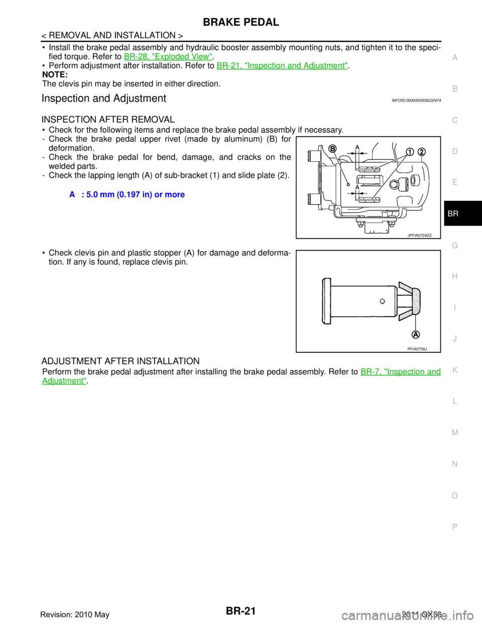
Check for the following items and replace the brake pedal assembly if necessary.
- Check the brake pedal upper rivet (made by aluminum) (B) for deformation.
- Check the brake pedal for bend, damage, and cracks on the welded parts.
- Check the lapping length (A) of sub-bracket (1) and slide plate (2).
Check clevis pin and plastic stopper (A) for damage and deforma-
tion. If any is found, replace clevis pin.
ADJUSTMENT AFTER INSTALLATION
Perform the brake pedal adjustment after installing the brake pedal assembly. Refer to BR-7, "Inspection and
Adjustment".
A : 5.0 mm (0.197 in) or more
JPFIA0724ZZ
PFIA0756J
Revision: 2010 May2011 QX56
Page 492 of 5598

BR-22
< REMOVAL AND INSTALLATION >
BRAKE PIPING
BRAKE PIPING
FRONT
FRONT : Exploded ViewINFOID:0000000006222475
1. Brake tube 2. Connector 3. Connector bracket
4. Hydraulic booster assembly 5. Lock plate 6. Brake hose bracket
7. Copper washer 8. Union bolt 9. Brake hose
A. To rear brake tube
Refer to GI-4, "
Components" for symbols in the figure.
JPFIA0794GB
Revision: 2010 May2011 QX56
Page 493 of 5598
BRAKE PIPINGBR-23
< REMOVAL AND INSTALLATION >
C
DE
G H
I
J
K L
M A
B
BR
N
O P
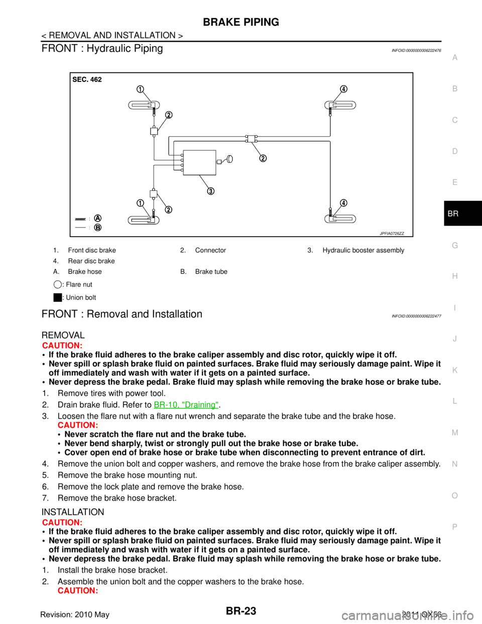
FRONT : Hydraulic PipingINFOID:0000000006222476
FRONT : Removal and InstallationINFOID:0000000006222477
REMOVAL
CAUTION:
If the brake fluid adheres to the brake caliper assembly and disc rotor, quickly wipe it off.
Never spill or splash brake fluid on painted surfaces. Brake fluid may seriously damage paint. Wipe it
off immediately and wash with wate r if it gets on a painted surface.
Never depress the brake pedal. Brake fluid may spl ash while removing the brake hose or brake tube.
1. Remove tires with power tool.
2. Drain brake fluid. Refer to BR-10, "
Draining".
3. Loosen the flare nut with a flare nut wrench and separate the brake tube and the brake hose.
CAUTION:
Never scratch the flare nut and the brake tube.
Never bend sharply, twist or strongly pull out the brake hose or brake tube.
Cover open end of brake hose or brake tube wh en disconnecting to prevent entrance of dirt.
4. Remove the union bolt and copper washers, and remove the brake hose from the brake caliper assembly.
5. Remove the brake hose mounting nut.
6. Remove the lock plate and remove the brake hose.
7. Remove the brake hose bracket.
INSTALLATION
CAUTION:
If the brake fluid adheres to the brake caliper assembly and disc rotor, quickly wipe it off.
Never spill or splash brake fluid on painted surfaces. Brake fluid may seriously damage paint. Wipe it
off immediately and wash with wate r if it gets on a painted surface.
Never depress the brake pedal. Brake fluid may spl ash while removing the brake hose or brake tube.
1. Install the brake hose bracket.
2. Assemble the union bolt and the copper washers to the brake hose. CAUTION:
1. Front disc brake 2. Connector 3. Hydraulic booster assembly
4. Rear disc brake
A. Brake hose B. Brake tube
: Flare nut
: Union bolt
JPFIA0726ZZ
Revision: 2010 May2011 QX56
Page 494 of 5598
BR-24
< REMOVAL AND INSTALLATION >
BRAKE PIPING
Never reuse the copper washer.
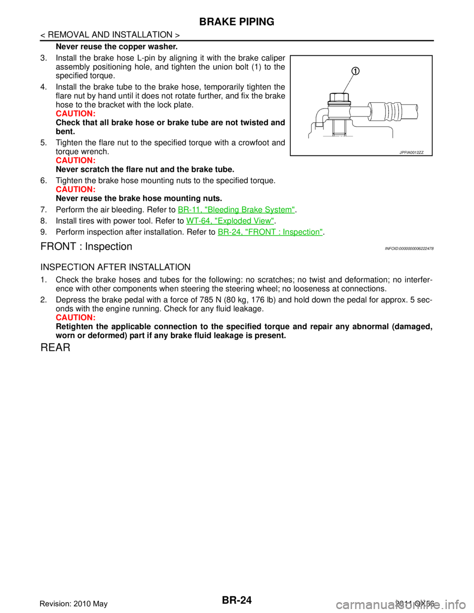
3. Install the brake hose L-pin by aligning it with the brake caliper assembly positioning hole, and tighten the union bolt (1) to the
specified torque.
4. Install the brake tube to the brake hose, temporarily tighten the flare nut by hand until it does not rotate further, and fix the brake
hose to the bracket with the lock plate.
CAUTION:
Check that all brake hose or brake tube are not twisted and
bent.
5. Tighten the flare nut to the specified torque with a crowfoot and torque wrench.
CAUTION:
Never scratch the flare nut and the brake tube.
6. Tighten the brake hose mounting nuts to the specified torque. CAUTION:
Never reuse the brake hose mounting nuts.
7. Perform the air bleeding. Refer to BR-11, "
Bleeding Brake System".
8. Install tires with power tool. Refer to WT-64, "
Exploded View".
9. Perform inspection after installation. Refer to BR-24, "
FRONT : Inspection".
FRONT : InspectionINFOID:0000000006222478
INSPECTION AFTER INSTALLATION
1. Check the brake hoses and tubes for the following: no scratches; no twist and deformation; no interfer-
ence with other components when steering the steering wheel; no looseness at connections.
2. Depress the brake pedal with a force of 785 N (80 kg, 176 lb) and hold down the pedal for approx. 5 sec- onds with the engine running. Check for any fluid leakage.
CAUTION:
Retighten the applicable connection to the specified torque and repair any abnormal (damaged,
worn or deformed) part if any brake fluid leakage is present.
REAR
JPFIA0012ZZ
Revision: 2010 May2011 QX56
Page 495 of 5598

BRAKE PIPINGBR-25
< REMOVAL AND INSTALLATION >
C
DE
G H
I
J
K L
M A
B
BR
N
O P
REAR : Exploded ViewINFOID:0000000006222479
REAR : Hydraulic PipingINFOID:0000000006222480
1. Brake tube 2. Lock plate 3. Brake hose
4. Union bolt 5. Copper washer
A. To connector
Refer to GI-4, "
Components" for symbols in the figure.
JPFIA0795GB
JPFIA0726ZZ
Revision: 2010 May2011 QX56
Page 496 of 5598
BR-26
< REMOVAL AND INSTALLATION >
BRAKE PIPING
REAR : Removal and Installation
INFOID:0000000006222481
REMOVAL
CAUTION:
If the brake fluid adheres to the brake caliper assembly and disc rotor, quickly wipe it off.
Never spill or splash brake fluid on painted surfaces. Brake fluid may seriously damage paint. Wipe it
off immediately and wash with wate r if it gets on a painted surface.
Never depress the brake pedal. Brake fluid may spl ash while removing the brake hose or brake tube.
1. Remove tires with power tool.
2. Drain brake fluid. Refer to BR-10, "
Draining".
3. Loosen the flare nut with a flare nut wrench and separate the brake tube and the brake hose. CAUTION:
Never scratch the flare nut and the brake tube.
Never bend sharply, twist or strongly pull out the brake hose or brake tube.
Cover open end of brake hose or brake tube wh en disconnecting to prevent entrance of dirt.
4. Remove the union bolt and copper washers, and remove the brake hose from the brake caliper assembly.
5. Remove the lock plate and remove the brake hose.
INSTALLATION
CAUTION:
If the brake fluid adheres to the brake caliper assembly and disc rotor, quickly wipe it off.
Never spill or splash brake fluid on painted surfaces. Brake fluid may seriously damage paint. Wipe it
off immediately and wash with wate r if it gets on a painted surface.
Never depress the brake pedal. Brake fluid may spl ash while removing the brake hose or brake tube.
1. Assemble the union bolt and the copper washers to the brake hose. CAUTION:
Never reuse the copper washer.
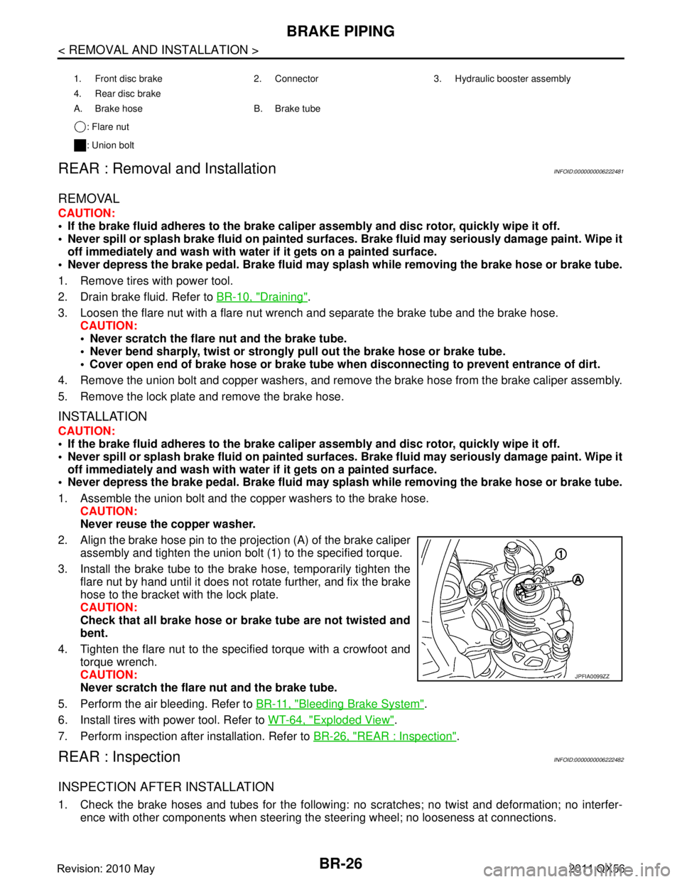
2. Align the brake hose pin to the projection (A) of the brake caliper
assembly and tighten the union bolt (1) to the specified torque.
3. Install the brake tube to the brake hose, temporarily tighten the flare nut by hand until it does not rotate further, and fix the brake
hose to the bracket with the lock plate.
CAUTION:
Check that all brake hose or brake tube are not twisted and
bent.
4. Tighten the flare nut to the specified torque with a crowfoot and torque wrench.
CAUTION:
Never scratch the flare nut and the brake tube.
5. Perform the air bleeding. Refer to BR-11, "
Bleeding Brake System".
6. Install tires with power tool. Refer to WT-64, "
Exploded View".
7. Perform inspection after installation. Refer to BR-26, "
REAR : Inspection".
REAR : InspectionINFOID:0000000006222482
INSPECTION AFTER INSTALLATION
1. Check the brake hoses and tubes for the following: no scratches; no twist and deformation; no interfer-
ence with other components when steering the steering wheel; no looseness at connections.
1. Front disc brake 2. Connector 3. Hydraulic booster assembly
4. Rear disc brake
A. Brake hose B. Brake tube
: Flare nut
: Union bolt
JPFIA0099ZZ
Revision: 2010 May2011 QX56
Page 497 of 5598
BRAKE PIPINGBR-27
< REMOVAL AND INSTALLATION >
C
DE
G H
I
J
K L
M A
B
BR
N
O P
2. Depress the brake pedal with a force of 785 N (80 kg, 176 lb) and hold down the pedal for approx. 5 sec- onds with the engine running. Check for any fluid leakage.
CAUTION:
Retighten the applicable connect ion to the specified torque and repair any abnormal (damaged,
worn or deformed) part if any brake fluid leakage is present.
Revision: 2010 May2011 QX56
Page 498 of 5598

BR-28
< REMOVAL AND INSTALLATION >
HYDRAULIC BOOSTER ASSEMBLY
HYDRAULIC BOOSTER ASSEMBLY
Exploded ViewINFOID:0000000006222483
REMOVAL
DISASSEMBLY
1. Hydraulic booster assembly 2. Lock nut 3. Clevis
Refer to GI-4, "
Components" for symbols in the figure.
JPFIA0767GB
Revision: 2010 May2011 QX56
Page 499 of 5598

HYDRAULIC BOOSTER ASSEMBLYBR-29
< REMOVAL AND INSTALLATION >
C
DE
G H
I
J
K L
M A
B
BR
N
O P
Removal and InstallationINFOID:0000000006222484
REMOVAL
1. Turn the ignition switch OFF. CAUTION:
Never turn the ignition switch ON before th e completion of the installation procedure.
2. Drain brake fluid. Refer to BR-10, "
Draining".
3. Depress the brake pedal 20 times or more to release the pressure from the accumulator. CAUTION:
Always perform this step before re moving the hydraulic booster assembly.
4. Disconnect hydraulic booster assembly harness connector.
5. Separate the brake tube from hydraulic booste r assembly with a flare nut wrench. Refer to BR-22,
"FRONT : Exploded View".
6. Remove brake tube from clip.
1. Reservoir cap 2. Lab el 3. Reservoir tank
4. Pin 5. Motor/accumulator assembly 6. Brake tube
7. Brake hose assembly 8. Grommet 9. Harness band
10. Collar 11. Bushing 12. Pin mount
13. Grommet 14. Bracket 15. Cap
16. Bushing 17. Bracket 18. ABS actuator and electric unit (con- trol unit)
19. Gasket 20. Spacer
: Apply brake fluid.
Refer to GI-4, "
Components" for symbols not described on the above.
JPFIA0748GB
Revision: 2010 May2011 QX56
Page 500 of 5598

BR-30
< REMOVAL AND INSTALLATION >
HYDRAULIC BOOSTER ASSEMBLY
7. Remove snap pin (1) and clevis pin (2) from clevis.
8. Remove nuts on hydraulic booster assembly and brake pedalassembly.
CAUTION:
Hold the hydraulic booster assembly so as to avoid drop-
ping out.
9. Remove hydraulic booster assembly. CAUTION:
Always hold (A) when removi ng the hydraulic booster
assembly.
Never deform or bend the brake tubes when removing the hydraulic booster assembly.
Always use a cushion or an equivalent to place the hydraulic booster assembly. Failure to do this may cause
uneven loads or impact and result in a malfunction.
10. After replacing hydraulic booster assembly, always follow the accumulator disposal procedure to discard the hydraulic booster
assembly. Refer to BR-33, "
Disposal".
INSTALLATION
Note the following, and install in the reverse order of removal.
Perform adjustment before installation. Refer to BR-32, "
Inspection and Adjustment".
Never reuse a hydraulic booster assembly after an e xcessive impact. (Slight impulse caused during installa-
tion work is acceptable.)
Never turn the ignition switch ON before the completion of the installation procedure.
Be careful not to damage hydraulic booster assembly stud bolt threads. If hydraulic booster assembly is
tilted during installation, the dash panel may damage the threads.
Always hold (A) when removing the hydraulic booster assembly.
Never deform or bend the brake tubes when installing the hydraulic booster assembly.
Always use a new gasket between the hydraulic booster assembly, spacer and the dash panel.
Replace the clevis pin if it is damaged. Refer to BR-21, "
Inspection
and Adjustment".
Perform the air bleeding. Refer to BR-11, "
Bleeding Brake Sys-
tem".
Perform the brake pedal adjustment after installing the brake pedal assembly and hydraulic booster assembly. Refer to BR-7, "
Inspec-
tion and Adjustment".
Perform inspection after installation. Refer to BR-32, "
Inspection and Adjustment".
Disassembly and AssemblyINFOID:0000000006222485
DISASSEMBLY
CAUTION:
Disassemble the hydraulic booster assembly when necessary.
1. Remove gaskets and spacer from hydraulic booster assembly.
JPFIA0019ZZ
JPFIA0749ZZ
JPFIA0749ZZ
Revision: 2010 May2011 QX56