ISUZU KB P190 2007 Workshop Repair Manual
Manufacturer: ISUZU, Model Year: 2007, Model line: KB P190, Model: ISUZU KB P190 2007Pages: 6020, PDF Size: 70.23 MB
Page 151 of 6020

HEATER AND AIR CONDITIONING 1-117
YES
• Disconnect the condenser fan relay connector condenser
fan.
YES
• Is there battery voltage between the engine room
harness connector terminal NO. 3 (C-24) and ground?Open circuit between the condenser fan
relay No.3 (X-10) and engine room harness
connector terminal No. 4 (C-24).
NO
• Is there continuity between the relay terminal No. 3 (X-
10) and engine room harness connector terminal No.4
(C-24)?
YES
Open circuit between the No. EB-13 fuse
and engine room harness connector
terminal No. 3 (C-24).
NO
YES
• Is there continuity between the engine room harness
connector terminal No. 2 (C-55) and the engine room
harness connector terminal No. 2 (C-24)?
Open circuit between the engine room
harness connector terminal No. 4 (X-15)
and the engine room harness connector
terminal No. 1 (C-24).
NO
• Disconnect the pressure switch.
• Is there continuity between the engine room harness
connector terminal No. 4 (X-15) and the engine room
harness connector terminal No. 1 (C-24).
Open circuit between the No. EB-13 fuse
and the engine room harness connector
terminal No. 2 (X-15).
NO
• Connect the A/C thermo relay connector.
• Disconnect the electronic thermostat.
Open circuit between the engine room
harness connector terminal No.3 (X-15)
and the engine room harness connector
terminal No. 1 (C-24).
NO
BACK TO CHAPTER INDEX
TO MODEL INDEX
ISUZU KB P190 2007
Page 152 of 6020
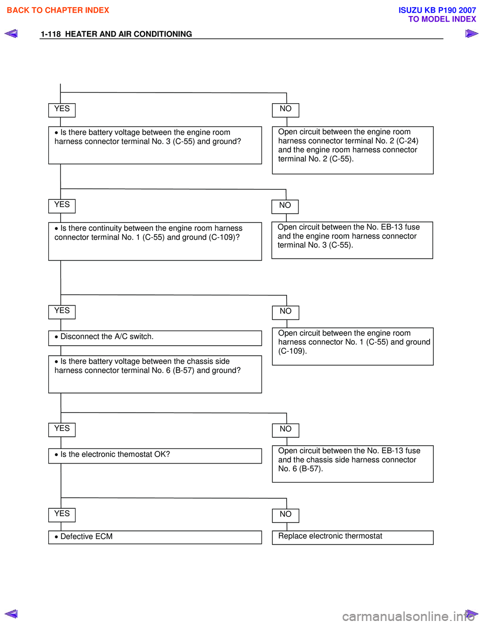
1-118 HEATER AND AIR CONDITIONING
YES
• Disconnect the A/C switch.
• Is there battery voltage between the chassis side
harness connector terminal No. 6 (B-57) and ground?
Open circuit between the engine room
harness connector terminal No. 2 (C-24)
and the engine room harness connector
terminal No. 2 (C-55).
NO YES
• Is there battery voltage between the engine room
harness connector terminal No. 3 (C-55) and ground?
Open circuit between the No. EB-13 fuse
and the engine room harness connector
terminal No. 3 (C-55).
NO YES
• Is there continuity between the engine room harness
connector terminal No. 1 (C-55) and ground (C-109)?
Open circuit between the engine room
harness connector No. 1 (C-55) and ground
(C-109).
NO
YES
• Is the electronic themostat OK? Open circuit between the No. EB-13 fuse
and the chassis side harness connector
No. 6 (B-57).
NO
YES
• Defective ECM Replace electronic thermostat
NO
BACK TO CHAPTER INDEX
TO MODEL INDEX
ISUZU KB P190 2007
Page 153 of 6020
HEATER AND AIR CONDITIONING 1-119
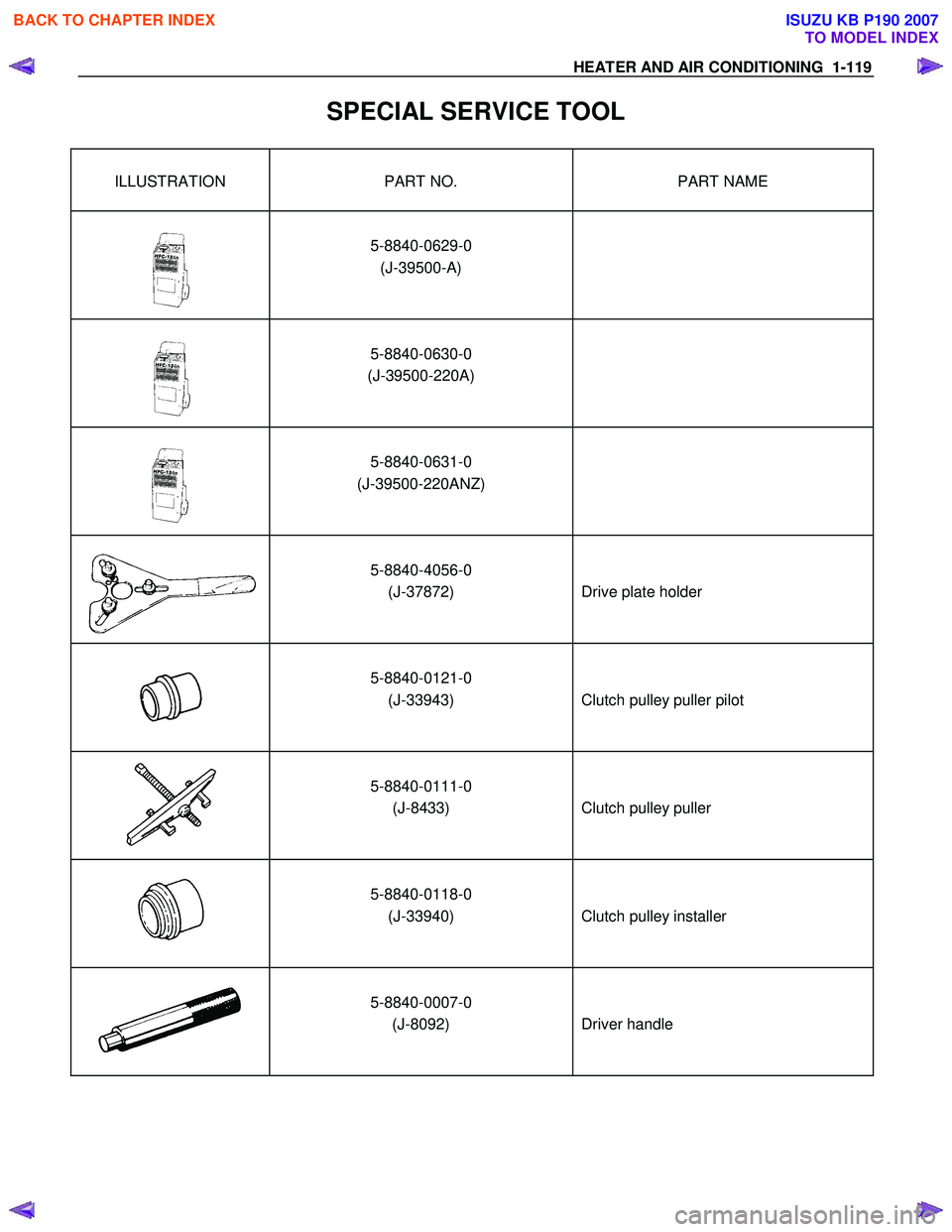
SPECIAL SERVICE TOOL
ILLUSTRATION PART NO. PART NAME
5-8840-0629-0 (J-39500-A)
5-8840-0630-0
(J-39500-220A)
5-8840-0631-0
(J-39500-220ANZ)
5-8840-4056-0 (J-37872)
Drive plate holder
5-8840-0121-0 (J-33943)
Clutch pulley puller pilot
5-8840-0111-0 (J-8433)
Clutch pulley puller
5-8840-0118-0 (J-33940)
Clutch pulley installer
5-8840-0007-0 (J-8092)
Driver handle
BACK TO CHAPTER INDEX
TO MODEL INDEX
ISUZU KB P190 2007
Page 154 of 6020
FRAME AND CAB 2 -1
SECTI ON 2
FRAME AND CAB
TA BLE OF CONTENTS
PA GE
Section 2A Frame and Bumper ........................................................................................... 157
Section 2B Sheet Metal........................... ............................................................................. 200
TO MODEL INDEX
BACK TO MAIN INDEX
ISUZU KB P190 2007
Page 155 of 6020

FRAME AND BUMPER 2A-1
SECTION 2A
FRAME AND BUMPER
TABLE OF CONTENTS
Front Bumper (A type) ...................................................................................................... 2A- 2
Front Bumper (B type)....................................................................................................... 2A- 5
Rear Step Bumper ............................................................................................................. 2A - 8
Rear Bumper and Rear Guard .......................................................................................... 2A- 11
Front Air Dam .................................................................................................................. ...2A - 13
Frame Dimensions ............................................................................................................ 2A- 14
PAGE
BACK TO CHAPTER INDEX
TO MODEL INDEX
ISUZU KB P190 2007
Page 156 of 6020
2A-2 FRAME AND BUMPER
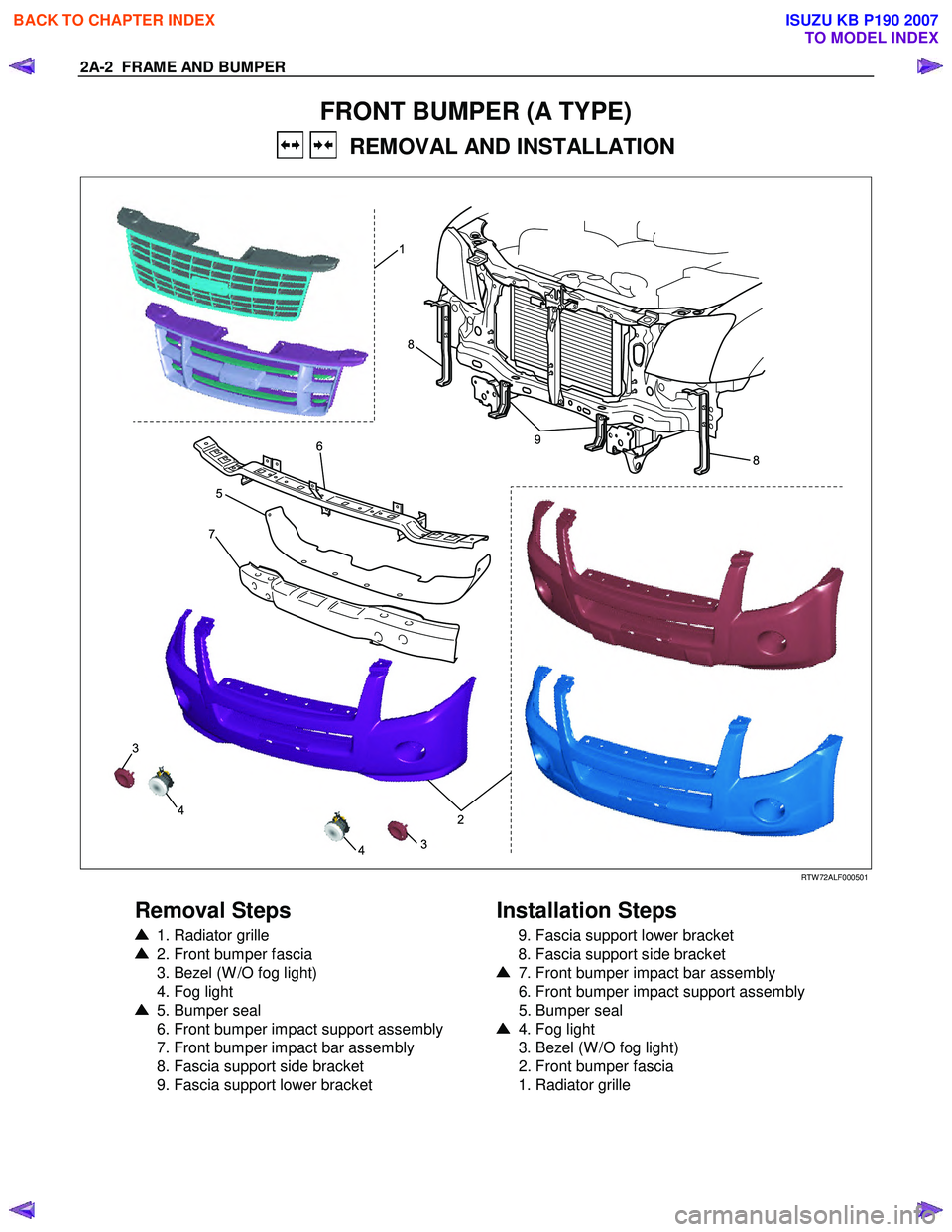
FRONT BUMPER (A TYPE)
REMOVAL AND INSTALLATION
8
8
9
2
1
7
5
4
43
3
6
RTW 72ALF000501
Removal Steps
1. Radiator grille
2. Front bumper fascia
3. Bezel (W /O fog light)
4. Fog light
5. Bumper seal
6. Front bumper impact support assembly
7. Front bumper impact bar assembly
8. Fascia support side bracket
9. Fascia support lower bracket
Installation Steps
9. Fascia support lower bracket
8. Fascia support side bracket
7. Front bumper impact bar assembly
6. Front bumper impact support assembly
5. Bumper seal
4. Fog light
3. Bezel (W /O fog light)
2. Front bumper fascia
1. Radiator grille
BACK TO CHAPTER INDEX
TO MODEL INDEX
ISUZU KB P190 2007
Page 157 of 6020
FRAME AND BUMPER 2A-3
Important Operations - Removal
1. Radiator Grille
Refer to the Radiator Grille in this section.
RTW 72ASH000501
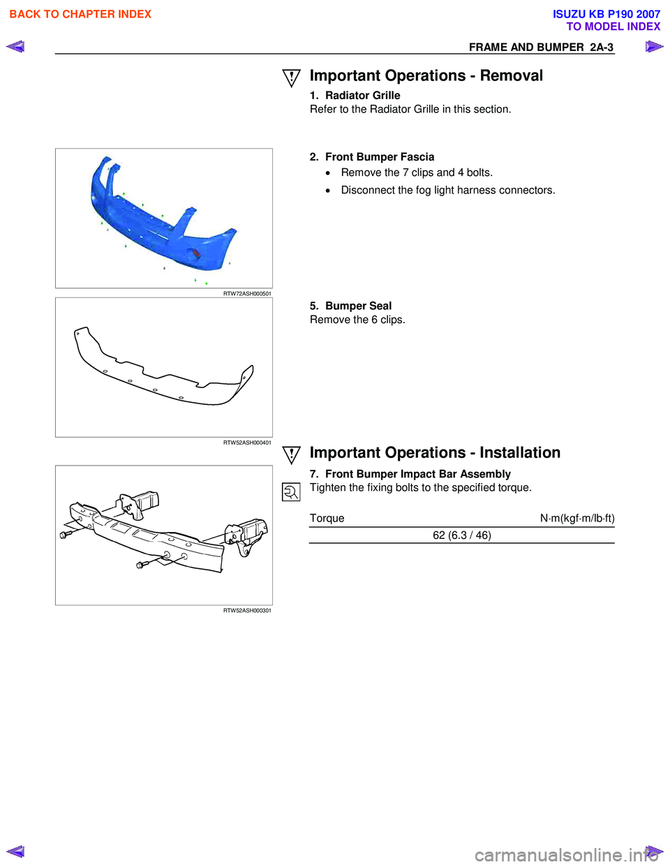
2. Front Bumper Fascia
• Remove the 7 clips and 4 bolts.
• Disconnect the fog light harness connectors.
RTW 52ASH000401
5. Bumper Seal
Remove the 6 clips.
Important Operations - Installation
RTW 52ASH000301
7. Front Bumper Impact Bar Assembly
Tighten the fixing bolts to the specified torque.
Torque N ⋅m(kgf ⋅m/lb ⋅ft)
62 (6.3 / 46)
BACK TO CHAPTER INDEX
TO MODEL INDEX
ISUZU KB P190 2007
Page 158 of 6020
2A-4 FRAME AND BUMPER
RTW 72ASH000601
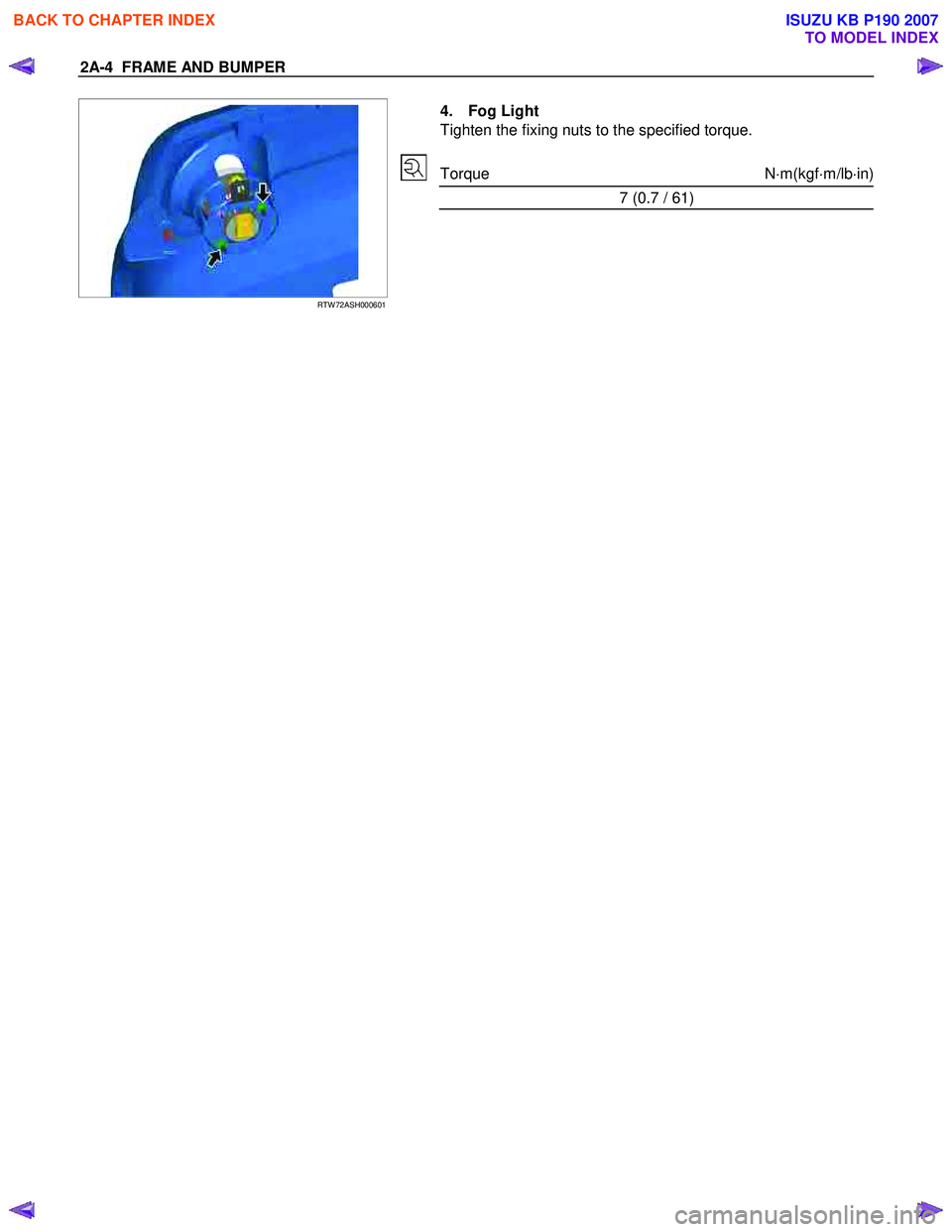
4. Fog Light
Tighten the fixing nuts to the specified torque.
Torque N ⋅m(kgf ⋅m/lb ⋅in)
7 (0.7 / 61)
BACK TO CHAPTER INDEX
TO MODEL INDEX
ISUZU KB P190 2007
Page 159 of 6020
FRAME AND BUMPER 2A-5
FRONT BUMPER (B TYPE)
REMOVAL AND INSTALLATION
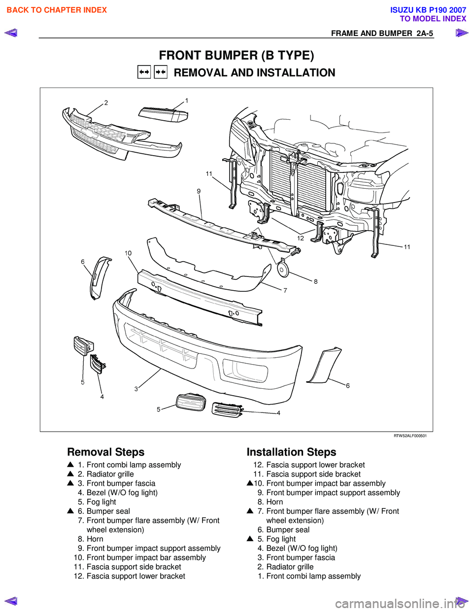
RTW 52ALF000501
Removal Steps
1. Front combi lamp assembly
2. Radiator grille
3. Front bumper fascia
4. Bezel (W /O fog light)
5. Fog light
6. Bumper seal
7. Front bumper flare assembly (W / Front
wheel extension)
8. Horn
9. Front bumper impact support assembly
10. Front bumper impact bar assembly
11. Fascia support side bracket
12. Fascia support lower bracket
Installation Steps
12. Fascia support lower bracket
11. Fascia support side bracket
10. Front bumper impact bar assembly
9. Front bumper impact support assembly
8. Horn
7. Front bumper flare assembly (W / Front
wheel extension)
6. Bumper seal
5. Fog light
4. Bezel (W /O fog light)
3. Front bumper fascia
2. Radiator grille
1. Front combi lamp assembly
BACK TO CHAPTER INDEX
TO MODEL INDEX
ISUZU KB P190 2007
Page 160 of 6020
2A-6 FRAME AND BUMPER
Important Operations - Removal
1. Front Combi Lamp Assembly
2. Radiator Grille
Refer to the Radiator Grille in this section.
RTW 52ASH000101
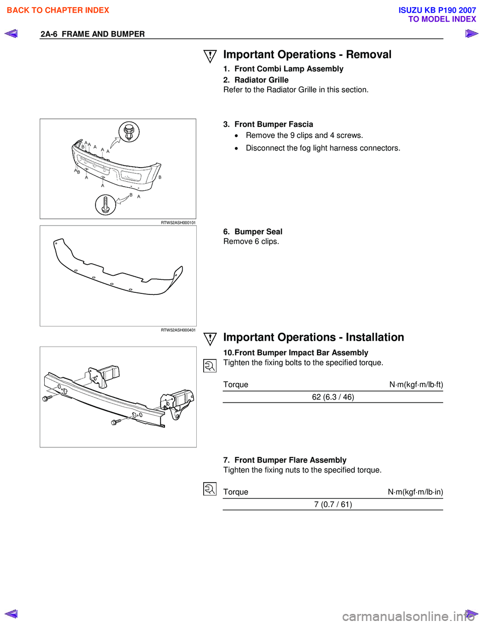
3. Front Bumper Fascia
• Remove the 9 clips and 4 screws.
• Disconnect the fog light harness connectors.
RTW 52ASH000401
6. Bumper Seal
Remove 6 clips.
Important Operations - Installation
10. Front Bumper Impact Bar Assembly
Tighten the fixing bolts to the specified torque.
Torque N ⋅m(kgf ⋅m/lb ⋅ft)
62 (6.3 / 46)
7. Front Bumper Flare Assembly
Tighten the fixing nuts to the specified torque.
Torque N ⋅m(kgf ⋅m/lb ⋅in)
7 (0.7 / 61)
BACK TO CHAPTER INDEX
TO MODEL INDEX
ISUZU KB P190 2007