ISUZU KB P190 2007 Workshop Repair Manual
KB P190 2007
ISUZU
ISUZU
https://www.carmanualsonline.info/img/61/57177/w960_57177-0.png
ISUZU KB P190 2007 Workshop Repair Manual
Trending: cooling, bulb, differential, door, tire size, warning, wiring
Page 211 of 6020
2B-14 SHEET METAL
Important Operations - Installation
5. Control Cable
Reroute the control cable to its original position, and check to
see if the lock assembly and control lever work normally.
3. Engine Hood Lock Assembly
Adjustment
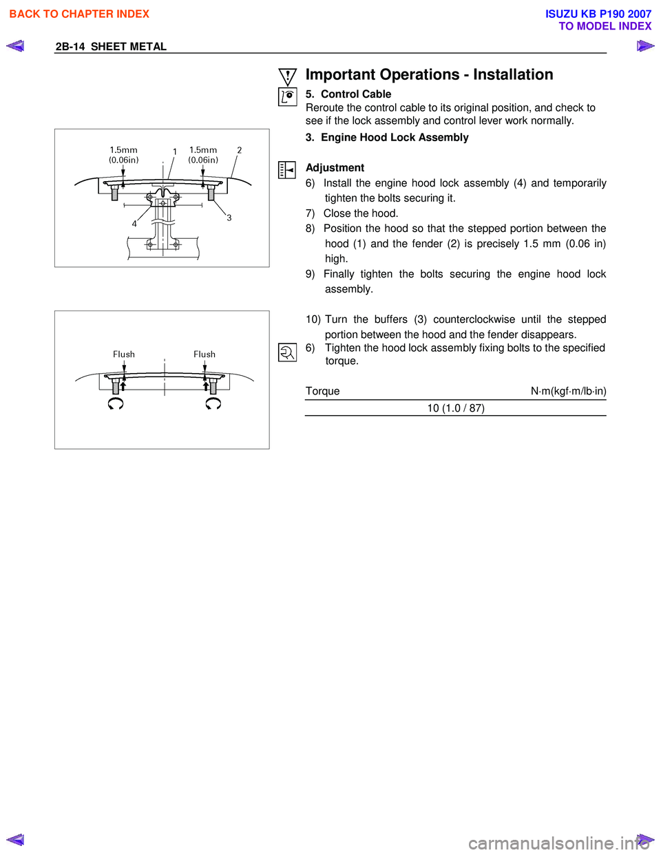
6) Install the engine hood lock assembly (4) and temporaril
y
tighten the bolts securing it.
7) Close the hood.
8) Position the hood so that the stepped portion between the hood (1) and the fender (2) is precisely 1.5 mm (0.06 in)
high.
9) Finally tighten the bolts securing the engine hood lock assembly.
10) Turn the buffers (3) counterclockwise until the stepped
portion between the hood and the fender disappears.
6) Tighten the hood lock assembly fixing bolts to the specified torque.
Torque N ⋅m(kgf ⋅m/lb ⋅in)
10 (1.0 / 87)
BACK TO CHAPTER INDEX
TO MODEL INDEX
ISUZU KB P190 2007
Page 212 of 6020
SHEET METAL 2B-15
FRONT FENDER PANEL (A TYPE)
REMOVAL AND INSTALLATION
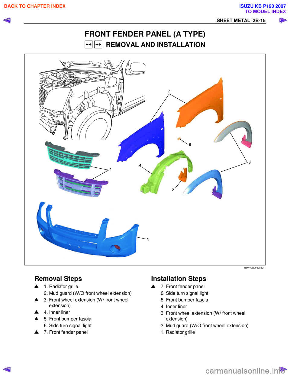
1
52
4
6
3
7
RTW 72BLF000201
Removal Steps
Installation Steps
1. Radiator grille
2. Mud guard (W /O front wheel extension)
3. Front wheel extension (W / front wheel
extension)
4. Inner liner
5. Front bumper fascia
6. Side turn signal light
7. Front fender panel
7. Front fender panel
6. Side turn signal light
5. Front bumper fascia
4. Inner liner
3. Front wheel extension (W / front wheel
extension)
2. Mud guard (W /O front wheel extension)
1. Radiator grille
BACK TO CHAPTER INDEX
TO MODEL INDEX
ISUZU KB P190 2007
Page 213 of 6020
2B-16 SHEET METAL
Important Operations - Removal
1. Radiator Grille
Refer to the Radiator Grille in this section.
3. Front wheel extension (W/front wheel extension)
Refer to the SECTION 10 “Front W heel Extension”.
4. Inner Liner
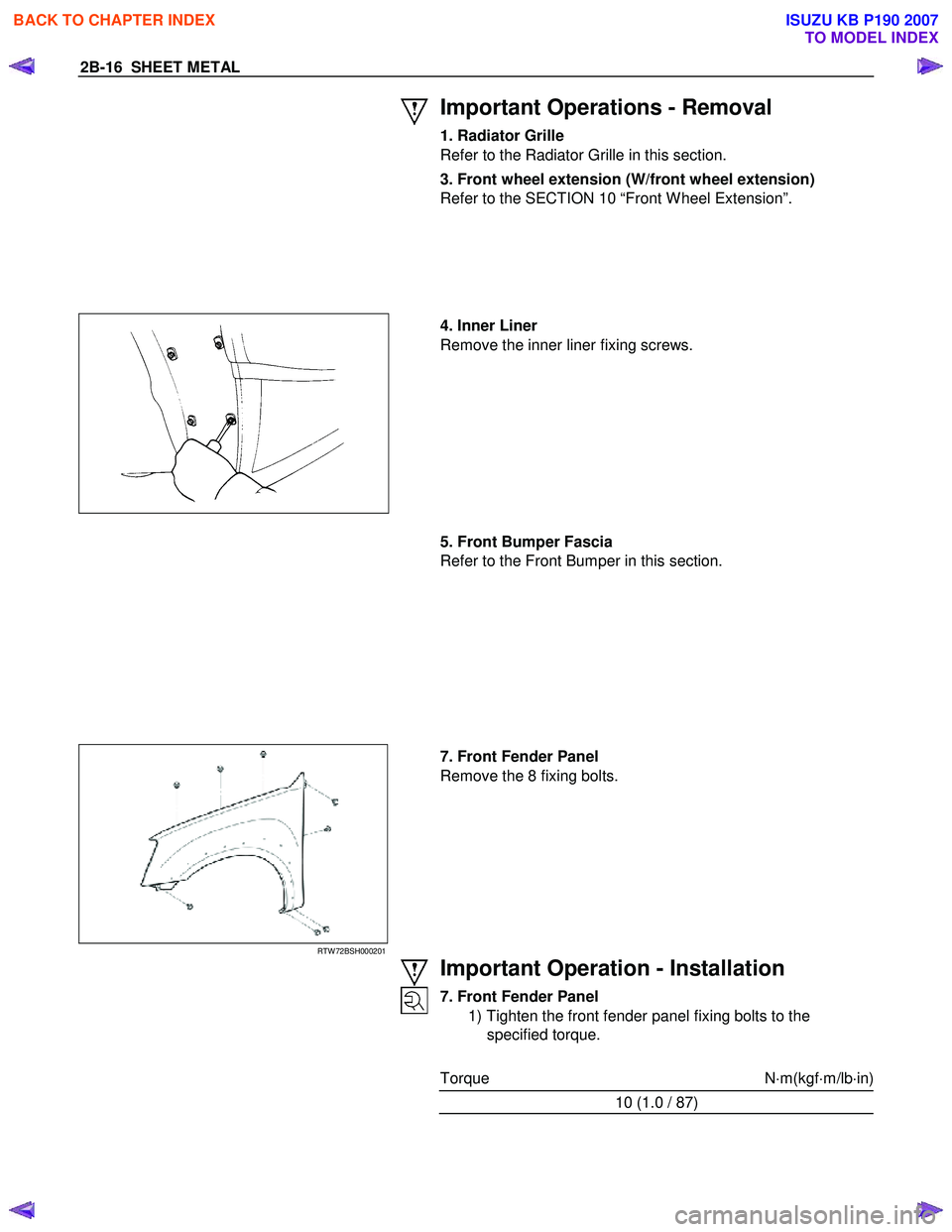
Remove the inner liner fixing screws.
5. Front Bumper Fascia
Refer to the Front Bumper in this section.
RTW 72BSH000201
7. Front Fender Panel
Remove the 8 fixing bolts.
Important Operation - Installation
7. Front Fender Panel
1) Tighten the front fender panel fixing bolts to the
specified torque.
Torque N ⋅m(kgf ⋅m/lb ⋅in)
10 (1.0 / 87)
BACK TO CHAPTER INDEX
TO MODEL INDEX
ISUZU KB P190 2007
Page 214 of 6020
SHEET METAL 2B-17
RTW 72BSH000601
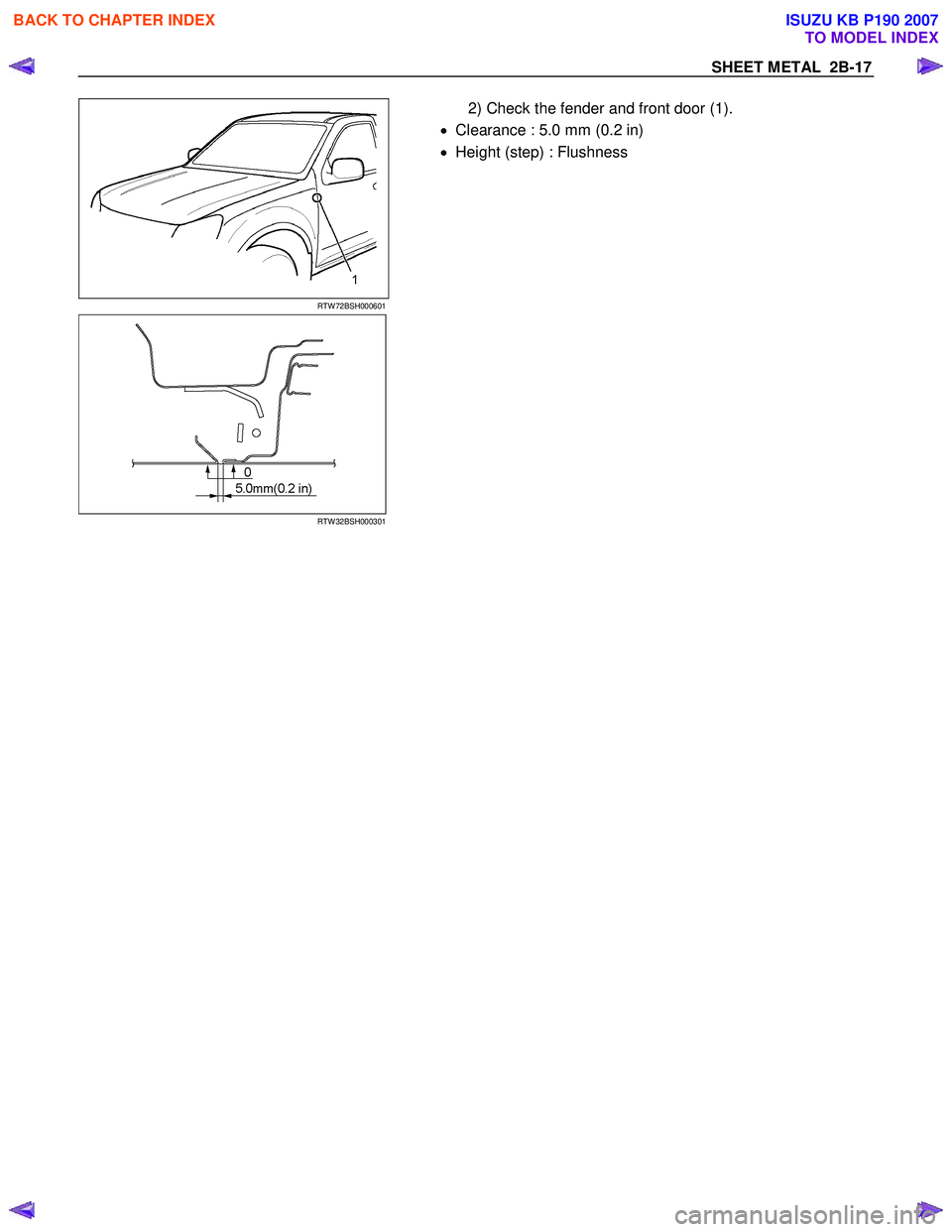
2) Check the fender and front door (1).
• Clearance : 5.0 mm (0.2 in)
• Height (step) : Flushness
RTW 32BSH000301
BACK TO CHAPTER INDEX
TO MODEL INDEX
ISUZU KB P190 2007
Page 215 of 6020
2B-18 SHEET METAL
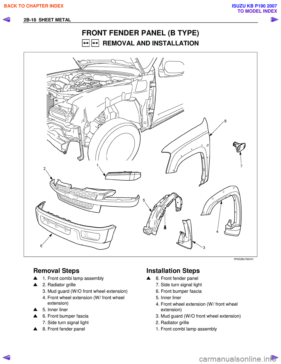
FRONT FENDER PANEL (B TYPE)
REMOVAL AND INSTALLATION
RTW 52BLF000101
Removal Steps Installation Steps
1. Front combi lamp assembly
2. Radiator grille
3. Mud guard (W /O front wheel extension)
4. Front wheel extension (W / front wheel
extension)
5. Inner liner
6. Front bumper fascia
7. Side turn signal light
8. Front fender panel
8. Front fender panel
7. Side turn signal light
6. Front bumper fascia
5. Inner liner
4. Front wheel extension (W / front wheel
extension)
3. Mud guard (W /O front wheel extension)
2. Radiator grille
1. Front combi lamp assembly
BACK TO CHAPTER INDEX
TO MODEL INDEX
ISUZU KB P190 2007
Page 216 of 6020
SHEET METAL 2B-19
Important Operations - Removal
1. Front Combi Lamp Assembly
2. Radiator Grille
Refer to the Radiator Grille in this section.
5. Inner Liner
Remove the inner liner fixing screws.
6. Front Bumper Fascia
Refer to the Front Bumper in this section.
RTW 52BSH000401
8. Front Fender Panel
Remove the 8 fixing bolts.
Important Operation - Installation
8. Front Fender Panel
1) Tighten the front fender panel fixing bolts to the
specified torque.
Torque N ⋅m(kgf ⋅m/lb ⋅in)
10 (1.0 / 87)
BACK TO CHAPTER INDEX
TO MODEL INDEX
ISUZU KB P190 2007
Page 217 of 6020
2B-20 SHEET METAL
RTW 72BSH001201
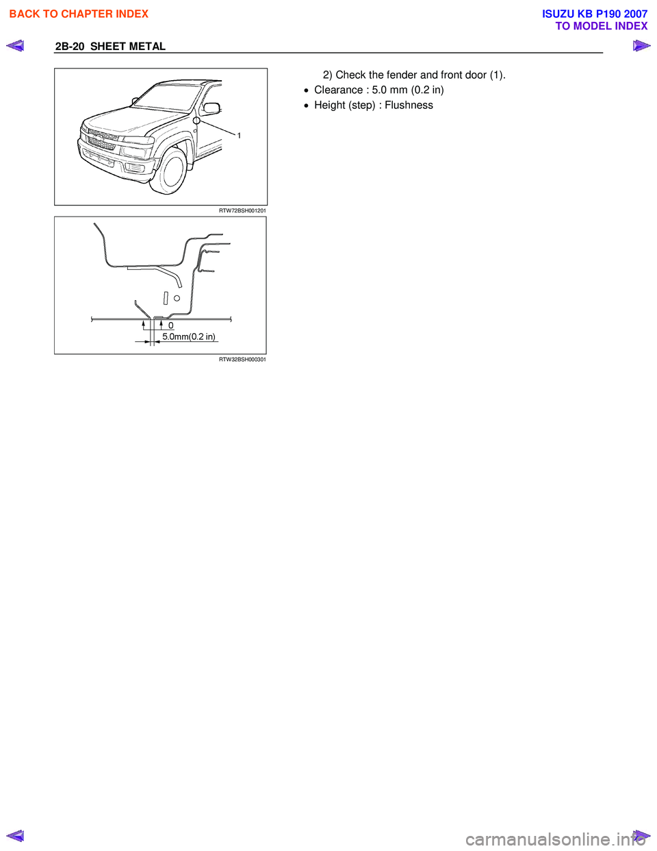
2) Check the fender and front door (1).
• Clearance : 5.0 mm (0.2 in)
• Height (step) : Flushness
RTW 32BSH000301
BACK TO CHAPTER INDEX
TO MODEL INDEX
ISUZU KB P190 2007
Page 218 of 6020
SHEET METAL 2B-21
RADIATOR GRILLE (A TYPE)
REMOVAL AND INSTALLATION
3
1
1 2
RTW 72BMF000501
Removal Steps
Installation Steps
1. Screw 4. Radiator grille
2. Clip 3. Bolt
3. Bolt 2. Clip
4. Radiator grille 1. Screw
Important Operation - Removal
2. Clip
Pull the grille together with the 2 clips from the vehicle.
BACK TO CHAPTER INDEX
TO MODEL INDEX
ISUZU KB P190 2007
Page 219 of 6020
2B-22 SHEET METAL
RADIATOR GRILLE (B TYPE)
REMOVAL AND INSTALLATION
RTW 52BMF000201
Removal Steps Installation Steps
1. Screw
2. Front combi lamp assembly
3. Screw
4. Clip
5. Radiator grille
5. Radiator grille
4. Clip
3. Screw
2. Front combi lamp assembly
1. Screw
Important Operation - Removal
4. Clip
• Use a screwdriver to release the 4 clips at the top of the
radiator grille.
• Pull the grille together with the 2 bottom clips from the
vehicle.
BACK TO CHAPTER INDEX
TO MODEL INDEX
ISUZU KB P190 2007
Page 220 of 6020
SHEET METAL 2B-23
REAR BODY
REMOVAL AND INSTALLATION
A type
RTW 32MF000301
BACK TO CHAPTER INDEX
TO MODEL INDEX
ISUZU KB P190 2007
Trending: battery capacity, seat memory, battery replacement, fuse box, oil type, length, oil change
