ISUZU KB P190 2007 Workshop Repair Manual
KB P190 2007
ISUZU
ISUZU
https://www.carmanualsonline.info/img/61/57177/w960_57177-0.png
ISUZU KB P190 2007 Workshop Repair Manual
Trending: wiring diagram, headlamp, fog light, instrument panel, bolt pattern, tires, buttons
Page 241 of 6020
2B-44 SHEET METAL
SIDE BODY SECTION (REGULAR CAB)
4241
4443
BACK TO CHAPTER INDEX
TO MODEL INDEX
ISUZU KB P190 2007
Page 242 of 6020
SHEET METAL 2B-45
2345
4625
BACK TO CHAPTER INDEX
TO MODEL INDEX
ISUZU KB P190 2007
Page 243 of 6020
2B-46 SHEET METAL
SIDE BODY SECTION (EXTEND CAB)
4241
4443
BACK TO CHAPTER INDEX
TO MODEL INDEX
ISUZU KB P190 2007
Page 244 of 6020
SHEET METAL 2B-47
2945
4731
BACK TO CHAPTER INDEX
TO MODEL INDEX
ISUZU KB P190 2007
Page 245 of 6020
2B-48 SHEET METAL
SIDE BODY SECTION; FRONT SIDE (CREW CAB)
4142
4443
BACK TO CHAPTER INDEX
TO MODEL INDEX
ISUZU KB P190 2007
Page 246 of 6020
SHEET METAL 2B-49
4845
6050
BACK TO CHAPTER INDEX
TO MODEL INDEX
ISUZU KB P190 2007
Page 247 of 6020
2B-50 SHEET METAL
SIDE BODY SECTION; REAR SIDE (CREW CAB)
48 54
6261
BACK TO CHAPTER INDEX
TO MODEL INDEX
ISUZU KB P190 2007
Page 248 of 6020
STEERING SUSPENSION WHEELS AND TIRES 3-1
SECTI ON 3
STEERING SUSPENSION
TA BLE OF CONTENTS
Section 3A Front A lignment ................................................... ...................................... 249
PA
GE
Section 3B Power Assited Steering System ............................................................... 262
Section 3C Front Suspension ............................................................................... ...... 320
Section 3D Rear Suspension ................................................. ....................................... 3 85
Section 3E Wheels and Tires ................................................. ....................................... 405
WHEELS AND TIRES
TO MODEL INDEX
BACK TO MAIN INDEX
ISUZU KB P190 2007
Page 249 of 6020
2 2
×
××
×
4
×
××
×
×
××
×
F
R O NT ALIG NM EN T 3A -1
SECTIO N 3A
FRONT ALIGNMENT
TABLE OF CONTENTS
Front End A lignment Inspection and A dju st ment ......................................................... 3A-
PA
GE
General Descript ion ..................................................................................................... 3A-
Inspect ion .................................................................................................................... .3A- 3
A lig nm en t f o r 4 2 ( except High Ride Suspension) ........................................................ 3A-
A lignme nt for 4 2 (High Ride Suspension) and 4 4 ...................................................... 3A- 10
BACK TO CHAPTER INDEX
TO MODEL INDEX
ISUZU KB P190 2007
Page 250 of 6020

3A-2 FRONT ALIGNMENT
Front End Alignment Inspection and
Adjustment
General Description
“Front End Alignment” refers to the angular relationship
between the front wheels, the front suspension attaching parts
and the ground.
Proper front end alignment must be maintained in order to
insure efficient steering, good directional stability and to
prevent abnormal tire wear.
The most important factors of front end alignment are wheel
toe-in, wheel camber and axle caster.
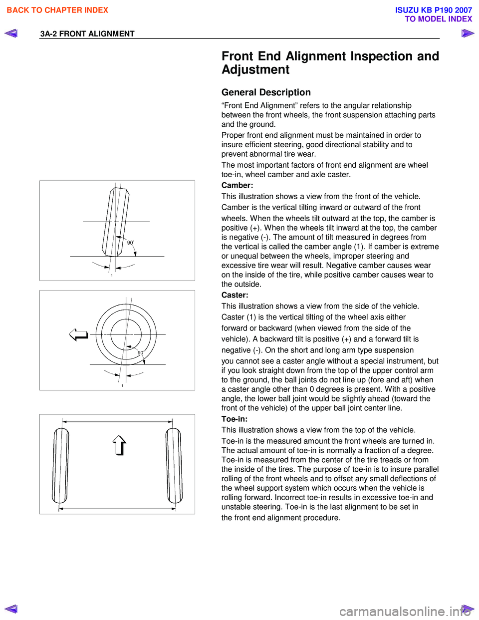
Camber:
This illustration shows a view from the front of the vehicle.
Camber is the vertical tilting inward or outward of the front
wheels. W hen the wheels tilt outward at the top, the camber is
positive (+). W hen the wheels tilt inward at the top, the camber
is negative (-). The amount of tilt measured in degrees from
the vertical is called the camber angle (1). If camber is extreme
or unequal between the wheels, improper steering and
excessive tire wear will result. Negative camber causes wear
on the inside of the tire, while positive camber causes wear to
the outside.
Caster:
This illustration shows a view from the side of the vehicle.
Caster (1) is the vertical tilting of the wheel axis either
forward or backward (when viewed from the side of the
vehicle). A backward tilt is positive (+) and a forward tilt is
negative (-). On the short and long arm type suspension
you cannot see a caster angle without a special instrument, but
if you look straight down from the top of the upper control arm
to the ground, the ball joints do not line up (fore and aft) when
a caster angle other than 0 degrees is present. W ith a positive
angle, the lower ball joint would be slightly ahead (toward the
front of the vehicle) of the upper ball joint center line.
Toe-in:
This illustration shows a view from the top of the vehicle.
Toe-in is the measured amount the front wheels are turned in.
The actual amount of toe-in is normally a fraction of a degree.
Toe-in is measured from the center of the tire treads or from
the inside of the tires. The purpose of toe-in is to insure parallel
rolling of the front wheels and to offset any small deflections of
the wheel support system which occurs when the vehicle is
rolling forward. Incorrect toe-in results in excessive toe-in and
unstable steering. Toe-in is the last alignment to be set in
the front end alignment procedure.
BACK TO CHAPTER INDEX
TO MODEL INDEX
ISUZU KB P190 2007
Trending: oil temperature, load capacity, steering wheel adjustment, transmission fluid, jack points, automatic transmission, checking oil


