ISUZU KB P190 2007 Workshop Repair Manual
Manufacturer: ISUZU, Model Year: 2007, Model line: KB P190, Model: ISUZU KB P190 2007Pages: 6020, PDF Size: 70.23 MB
Page 3011 of 6020
Engine Mechanical – V6 Page 6A1–234
Page 6A1–234
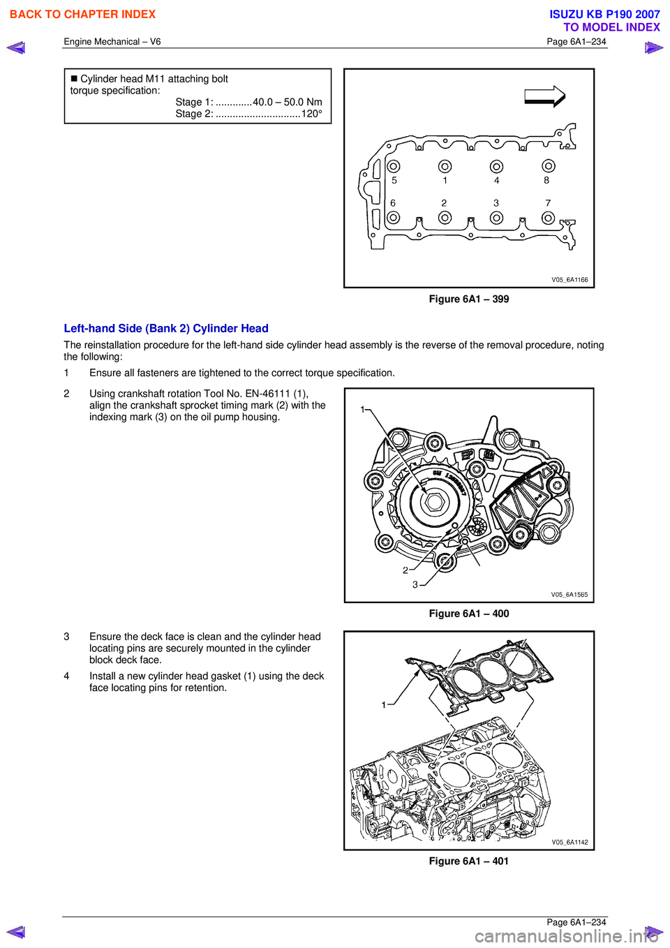
�„ Cylinder head M11 attaching bolt
torque specification:
Stage 1:............. 40.0 – 50.0 Nm
Stage 2:.............................. 120°
Figure 6A1 – 399
Left-hand Side (Bank 2) Cylinder Head
The reinstallation procedure for the left-hand side cylinder head a ssembly is the reverse of the removal procedure, noting
the following:
1 Ensure all fasteners are tightened to the correct torque specification.
2 Using crankshaft rotation Tool No. EN-46111 (1), align the crankshaft sprocket timing mark (2) with the
indexing mark (3) on the oil pump housing.
Figure 6A1 – 400
3 Ensure the deck face is clean and the cylinder head locating pins are securely mounted in the cylinder
block deck face.
4 Install a new cylinder head gasket (1) using the deck face locating pins for retention.
Figure 6A1 – 401
BACK TO CHAPTER INDEX
TO MODEL INDEX
ISUZU KB P190 2007
Page 3012 of 6020
Engine Mechanical – V6 Page 6A1–235
Page 6A1–235
5 Align the cylinder head with the locating pins.
6 Place the cylinder head in position on the deck face.
NOTE
Do not allow oil on the cylinder head bolt
bosses.
CAUTION
Do not reuse the old M11 cylinder head bolts
(1 to 8 inclusive).
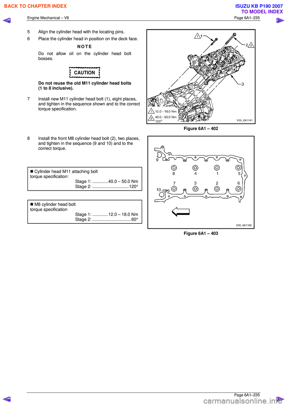
7 Install new M11 cylinder head bolt (1), eight places, and tighten in the sequence shown and to the correct
torque specification.
Figure 6A1 – 402
8 Install the front M8 cylinder head bolt (2), two places, and tighten in the sequence (9 and 10) and to the
correct torque.
�„ Cylinder head M11 attaching bolt
torque specification:
Stage 1:............. 40.0 – 50.0 Nm
Stage 2:.............................. 120°
�„ M8 cylinder head bolt
torque specification
Stage 1:............. 12.0 – 18.0 Nm
Stage 2:................................ 60°
Figure 6A1 – 403
BACK TO CHAPTER INDEX
TO MODEL INDEX
ISUZU KB P190 2007
Page 3013 of 6020
Engine Mechanical – V6 Page 6A1–236
Page 6A1–236
3.24 Engine Mounts and Brackets
Remove
1 Remove the exhaust manifold assembly from the side of the engine where the engine mount is to be removed,
refer to 3.11 Exhaust Manifold Assembly .
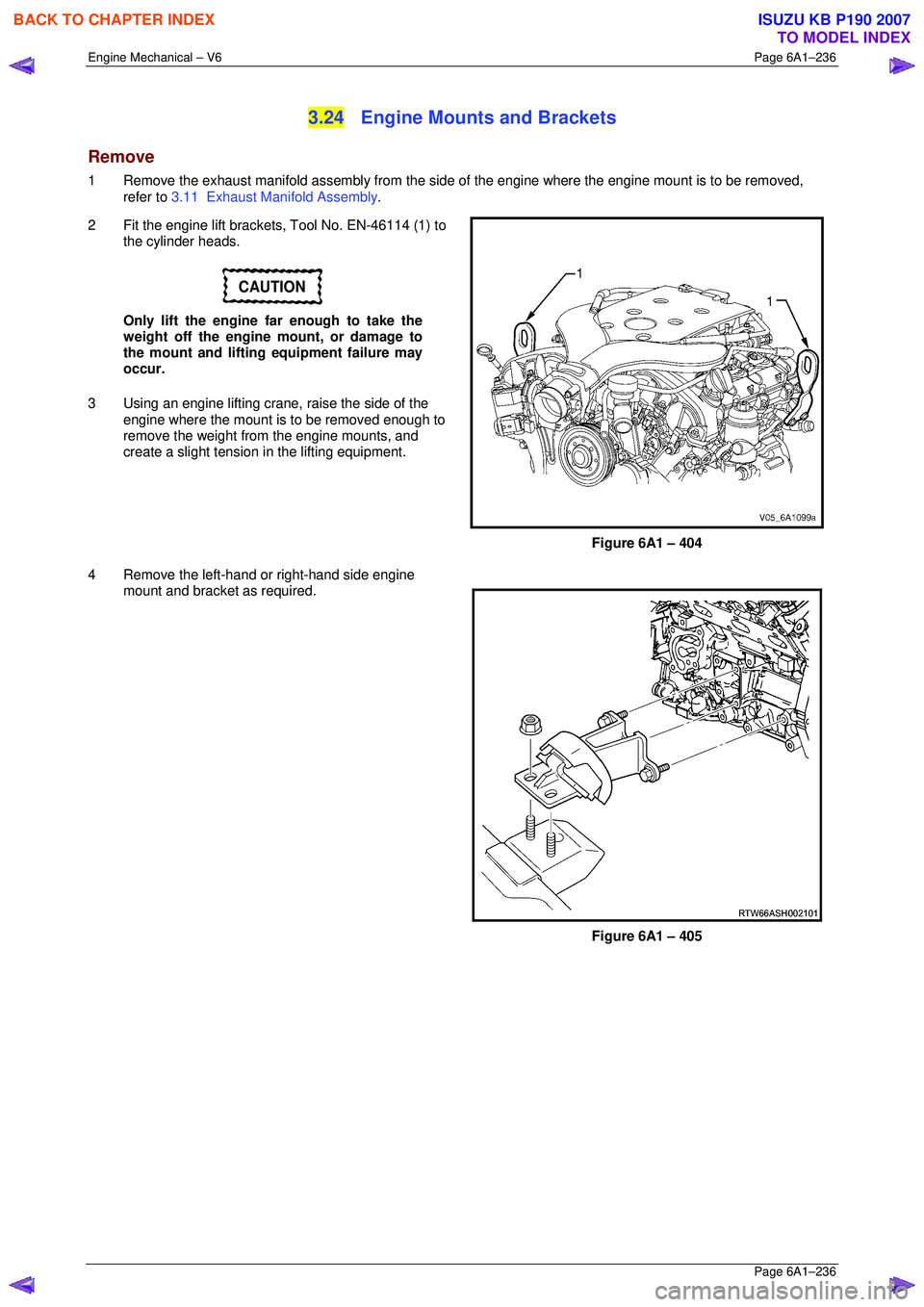
2 Fit the engine lift brackets, Tool No. EN-46114 (1) to the cylinder heads.
CAUTION
Only lift the engine far enough to take the
weight off the engine mount, or damage to
the mount and lifting equipment failure may
occur.
3 Using an engine lifting crane, raise the side of the
engine where the mount is to be removed enough to
remove the weight fr om the engine mounts, and
create a slight tension in the lifting equipment.
Figure 6A1 – 404
4 Remove the left-hand or right-hand side engine mount and bracket as required.
Figure 6A1 – 405
BACK TO CHAPTER INDEX
TO MODEL INDEX
ISUZU KB P190 2007
Page 3014 of 6020
Engine Mechanical – V6 Page 6A1–237
Page 6A1–237
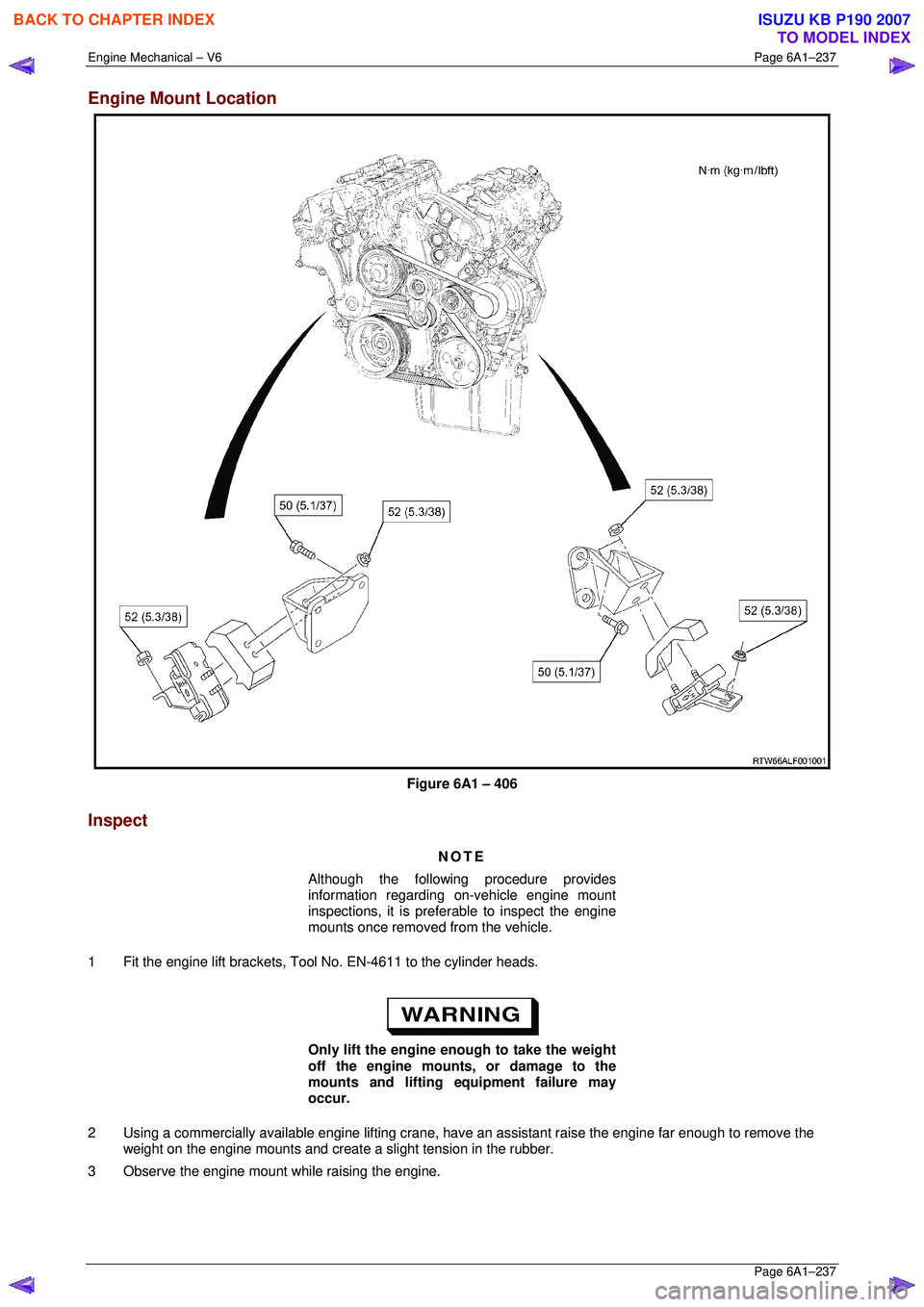
Engine Mount Location
Figure 6A1 – 406
Inspect
NOTE
Although the following procedure provides
information regarding on-vehicle engine mount
inspections, it is prefer able to inspect the engine
mounts once removed from the vehicle.
1 Fit the engine lift brackets, Tool No. EN-4611 to the cylinder heads.
Only lift the engine enough to take the weight
off the engine mounts, or damage to the
mounts and lifting equipment failure may
occur.
2 Using a commercially available engine lifting crane, hav e an assistant raise the engine far enough to remove the
weight on the engine mounts and create a slight tension in the rubber.
3 Observe the engine mount while raising the engine.
BACK TO CHAPTER INDEX
TO MODEL INDEX
ISUZU KB P190 2007
Page 3015 of 6020
Engine Mechanical – V6 Page 6A1–238
Page 6A1–238
4 Replace the engine mount if any of the following conditions are found:
• The hard rubber surface is cove red with heat check cracks,
• The rubber is split through the centre of the engine mount, or
• The rubber is separated from the me tal plate portion of the engine mount.
5 Remove the engine lift brackets, Tool No. EN-46114 from the engine.
Reinstall
The reinstallation procedure for the engi ne mounts is the reverse of the removal procedure, noting the following:
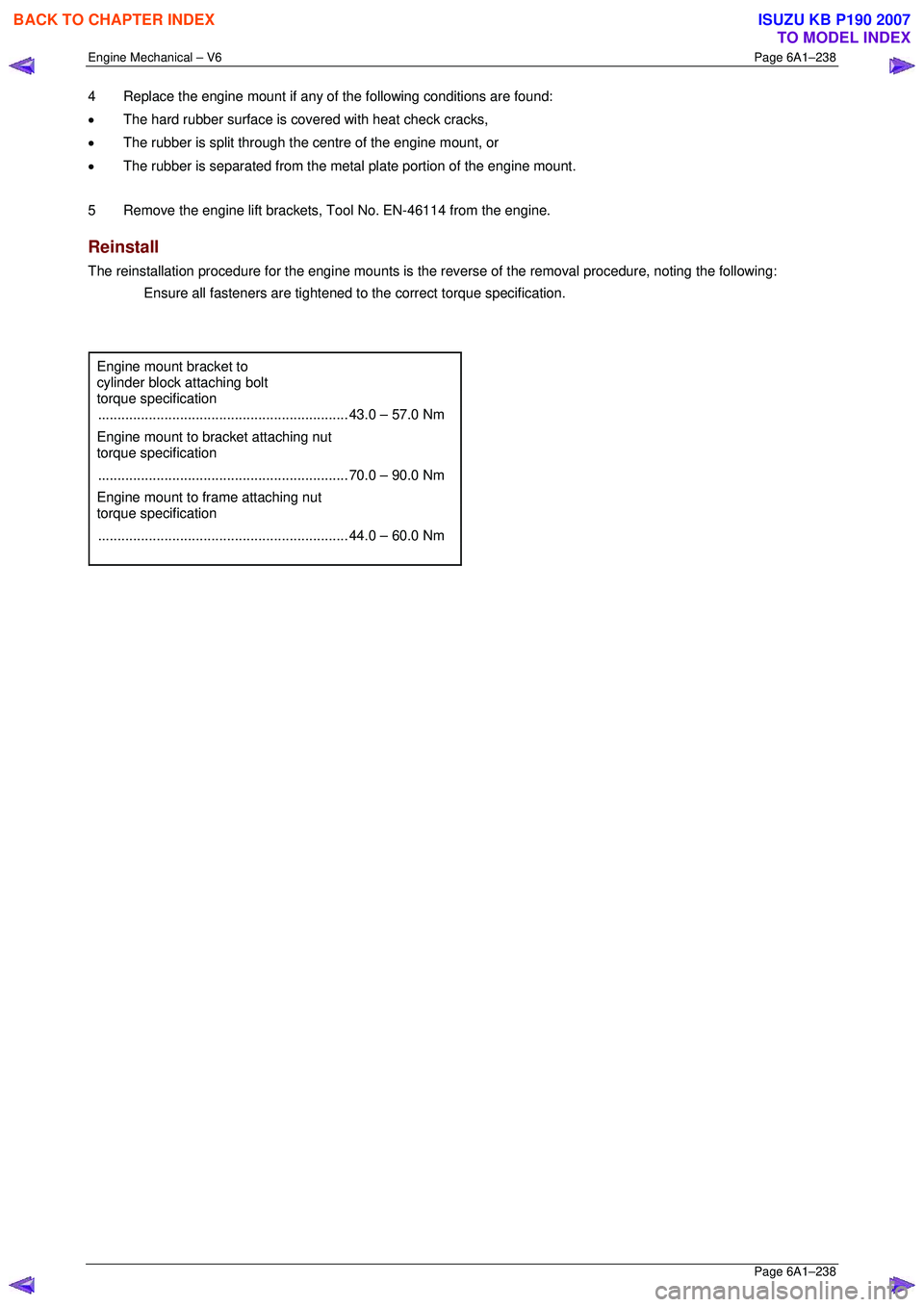
Ensure all fasteners are tightened to the correct torque specification.
Engine mount bracket to
cylinder block attaching bolt
torque specification
................................................................ 43.0 – 57.0 Nm
Engine mount to bracket attaching nut
torque specification
................................................................ 70.0 – 90.0 Nm
Engine mount to frame attaching nut
torque specification
................................................................ 44.0 – 60.0 Nm
BACK TO CHAPTER INDEX
TO MODEL INDEX
ISUZU KB P190 2007
Page 3016 of 6020
Engine Mechanical – V6 Page 6A1–239
Page 6A1–239
4 Major Service Operations
ATTENTION
The V6 engine is a combination of numerous components, containing machined, honed, polished and lapped
surfaces manufactured on the latest, high technology production equipment. Many of the components
contain tolerances measured in thousa ndths of a millimetre. Consequently, when any e ngine component is to
be serviced, care and cleanliness are extremely important.
Prior to re-assembly of the V6 engi ne, all components must be cleaned and inspected in accordance with the
relevant procedures throughout this section, and replaced or repaired where required.
In addition to cleaning and inspecting components, a liberal coating of engine oil should be applied to friction
surfaces during assembly to protect and lubr icate the surfaces on initial operation.
When performing any service operation contained in this Section, it should be understood that correct
cleaning and protection of machined surfaces and fricti on areas is part of the repair procedure. This is
considered standard workshop practice, even if not specifically stated. Torque values must be used as
specified during reassembly to ensure correct retention of all components.
Through out this section, fastener torque wrench sp ecifications may be accompanied with the following
identification marks:
■ Fasteners must be replaced after loosening.
Fasteners either have micro encapsulated sealant a pplied or incorporate a mechanical thread lock and
should only be re-used once. If in doubt, replacement is recommended.
If one of these identification marks is present alongs ide a fastener torque wrench specification, the
recommendation regarding that fastener must be adhered to.
4.1 Engine Removal
CAUTION
• Allow the engine to cool to at least 50 ° C,
before attempting fastener removal.
• As aluminium has a greater rate of thermal
expansion than that of cast iron,
aluminium bolt hole threads will change
dimension to a larger extent than cast iron
bolt threads.
• If a bolt or other threaded component is
removed before the engine is allowed to
cool to at least 50 ° C, threads could be
pulled from the cylinder block or cylinder
head.
• Do not use impact tools to remove bolts
during engine disassembly. While this may
be common practice with cast iron engine
components, use of th ese tools is likely to
pull the aluminium threads in the cylinder
block or head of this engine.
BACK TO CHAPTER INDEX
TO MODEL INDEX
ISUZU KB P190 2007
Page 3017 of 6020
Engine Mechanical – V6 Page 6A1–240
Page 6A1–240
Remove
1 Remove the skid plate.
2 Drain the radiator coolant, refer to Section 6B1 Engine Cooling – V6.
3 Disconnect the battery negative and positive terminal, refer to Section 8A Electrical Body & Chassis.
4 Remove the battery from the vehicle.
5 Depressurise the fuel sy stem pressure, refer to Section 6C Fuel System – V6 .
6 Make alignment marks on the bonnet and hinges in order to return the bonnet to the exact original position.
7 Remove the bonnet, refer to Section 2B Sheet Metal.
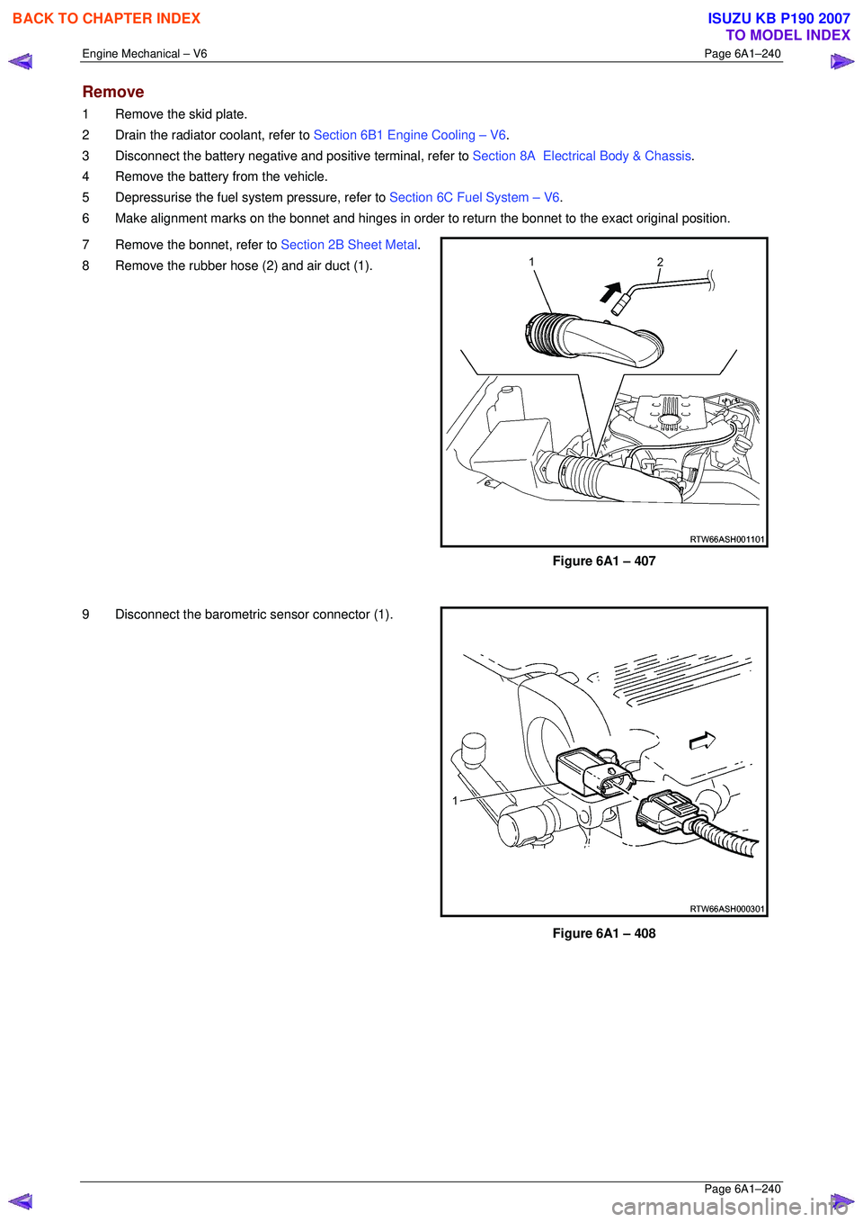
8 Remove the rubber hose (2) and air duct (1).
Figure 6A1 – 407
9 Disconnect the barometric sensor connector (1).
Figure 6A1 – 408
BACK TO CHAPTER INDEX
TO MODEL INDEX
ISUZU KB P190 2007
Page 3018 of 6020
Engine Mechanical – V6 Page 6A1–241
Page 6A1–241
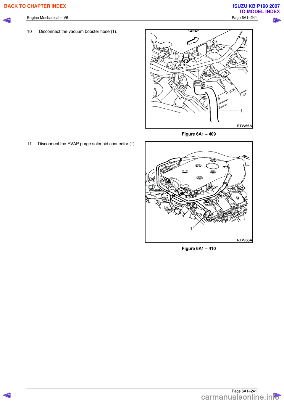
10 Disconnect the vacuum booster hose (1).
Figure 6A1 – 409
11 Disconnect the EVAP purge solenoid connector (1).
Figure 6A1 – 410
BACK TO CHAPTER INDEX
TO MODEL INDEX
ISUZU KB P190 2007
Page 3019 of 6020
Engine Mechanical – V6 Page 6A1–242
Page 6A1–242
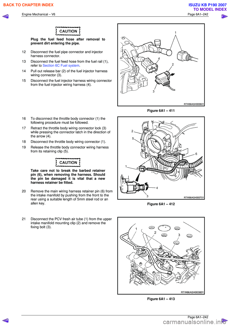
Plug the fuel feed hose after removal to
prevent dirt entering the pipe.
12 Disconnect the fuel pipe connector and injector harness connector.
13 Disconnect the fuel feed hose from the fuel rail (1),
refer to Section 6C Fuel system .
14 Pull out release bar (2) of the fuel injector harness
wiring connector (3).
15 Disconnect the fuel injector harness wiring connector from the fuel injector wiring harness (4).
Figure 6A1 – 411
16 To disconnect the throttle body connector (1) the following procedure must be followed.
17 Retract the throttle body wiring connector lock (3) while pressing the connector la tch in the direction of
the arrow (4).
18 Disconnect the throttle body wiring connector (1).
19 Release the throttle body connector wiring harness from its retaining clip (5).
Take care not to break the barbed retainer
pin (6), when removing the harness. Should
the pin be damaged it is vital that a new
harness retainer be fitted.
20 Remove the main wiring harness retainer pin (6) from the intake manifold by pushing from the front to the
rear using a suitable lengt h of 5mm steel rod or an
allen key.
Figure 6A1 – 412
21 Disconnect the PCV fresh air tube (1) from the upper intake manifold mounting clip (2) and remove the
fixing bolt (3).
Figure 6A1 – 413
BACK TO CHAPTER INDEX
TO MODEL INDEX
ISUZU KB P190 2007
Page 3020 of 6020
Engine Mechanical – V6 Page 6A1–243
Page 6A1–243
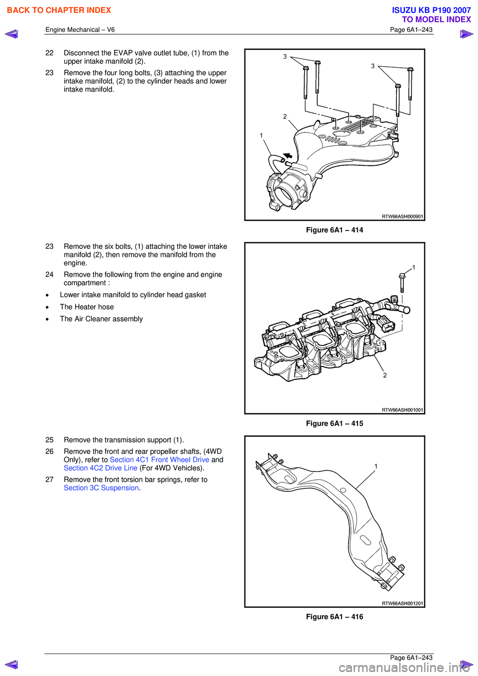
22 Disconnect the EVAP valve outlet tube, (1) from the
upper intake manifold (2).
23 Remove the four long bolts, (3) attaching the upper intake manifold, (2) to the cylinder heads and lower
intake manifold.
Figure 6A1 – 414
23 Remove the six bolts, (1) attaching the lower intake manifold (2), then remove the manifold from the
engine.
24 Remove the following from the engine and engine compartment :
• Lower intake manifold to cylinder head gasket
• The Heater hose
• The Air Cleaner assembly
Figure 6A1 – 415
25 Remove the transmission support (1).
26 Remove the front and rear propeller shafts, (4WD Only), refer to Section 4C1 Front Wheel Drive and
Section 4C2 Drive Line (For 4WD Vehicles).
27 Remove the front torsion bar springs, refer to Section 3C Suspension .
Figure 6A1 – 416
BACK TO CHAPTER INDEX
TO MODEL INDEX
ISUZU KB P190 2007