ISUZU KB P190 2007 Workshop Repair Manual
Manufacturer: ISUZU, Model Year: 2007, Model line: KB P190, Model: ISUZU KB P190 2007Pages: 6020, PDF Size: 70.23 MB
Page 3061 of 6020
Engine Mechanical – V6 Page 6A1–284
Page 6A1–284
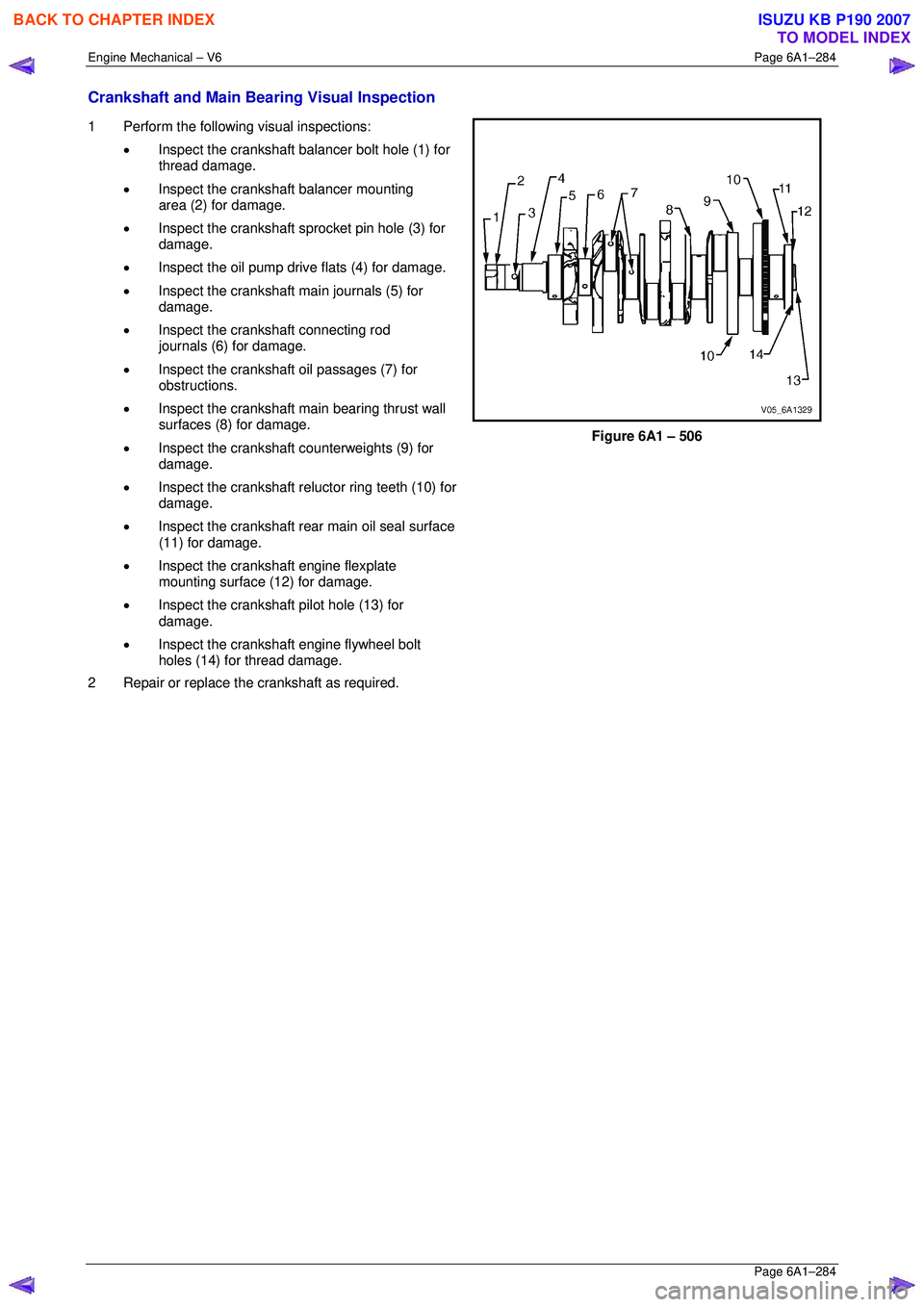
Crankshaft and Main Bearing Visual Inspection
1 Perform the following visual inspections:
• Inspect the crankshaft balancer bolt hole (1) for
thread damage.
• Inspect the crankshaft balancer mounting
area (2) for damage.
• Inspect the crankshaft sprocket pin hole (3) for
damage.
• Inspect the oil pump drive flats (4) for damage.
• Inspect the crankshaft main journals (5) for
damage.
• Inspect the crankshaft connecting rod
journals (6) for damage.
• Inspect the crankshaft oil passages (7) for
obstructions.
• Inspect the crankshaft main bearing thrust wall
surfaces (8) for damage.
• Inspect the crankshaft counterweights (9) for
damage.
• Inspect the crankshaft reluctor ring teeth (10) for
damage.
• Inspect the crankshaft rear main oil seal surface
(11) for damage.
• Inspect the crankshaft engine flexplate
mounting surface (12) for damage.
• Inspect the crankshaft pilot hole (13) for
damage.
• Inspect the crankshaft engine flywheel bolt
holes (14) for thread damage.
2 Repair or replace the crankshaft as required.
Figure 6A1 – 506
BACK TO CHAPTER INDEX
TO MODEL INDEX
ISUZU KB P190 2007
Page 3062 of 6020
Engine Mechanical – V6 Page 6A1–285
Page 6A1–285
Crankshaft Main Bearing Inspection
CAUTION
All connecting rod and main journal bearings
that have been used in a running engine must
be replaced. Never re-use the crankshaft or
connecting rod bearings.
NOTE
The following bearing wear conditions should be
used to diagnose engine operating conditions or
root cause of a condition.
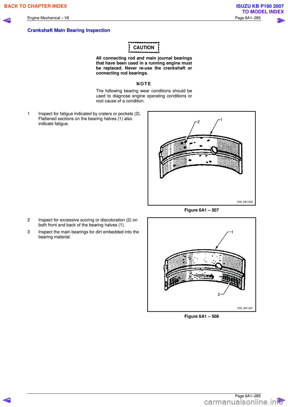
1 Inspect for fatigue indicated by craters or pockets (2). Flattened sections on the bearing halves (1) also
indicate fatigue.
Figure 6A1 – 507
2 Inspect for excessive sco ring or discoloration (2) on
both front and back of t he bearing halves (1).
3 Inspect the main bearings for dirt embedded into the bearing material.
Figure 6A1 – 508
BACK TO CHAPTER INDEX
TO MODEL INDEX
ISUZU KB P190 2007
Page 3063 of 6020
Engine Mechanical – V6 Page 6A1–286
Page 6A1–286
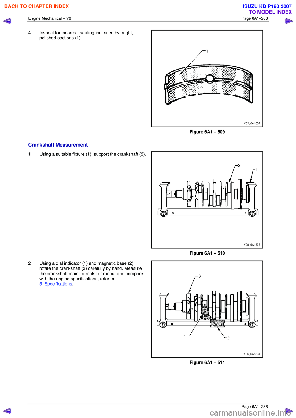
4 Inspect for incorrect seating indicated by bright,
polished sections (1).
Figure 6A1 – 509
Crankshaft Measurement
1 Using a suitable fixture (1 ), support the crankshaft (2).
Figure 6A1 – 510
2 Using a dial indicator (1) and magnetic base (2), rotate the crankshaft (3) carefully by hand. Measure
the crankshaft main journals for runout and compare
with the engine specifications, refer to
5 Specifications .
Figure 6A1 – 511
BACK TO CHAPTER INDEX
TO MODEL INDEX
ISUZU KB P190 2007
Page 3064 of 6020
Engine Mechanical – V6 Page 6A1–287
Page 6A1–287
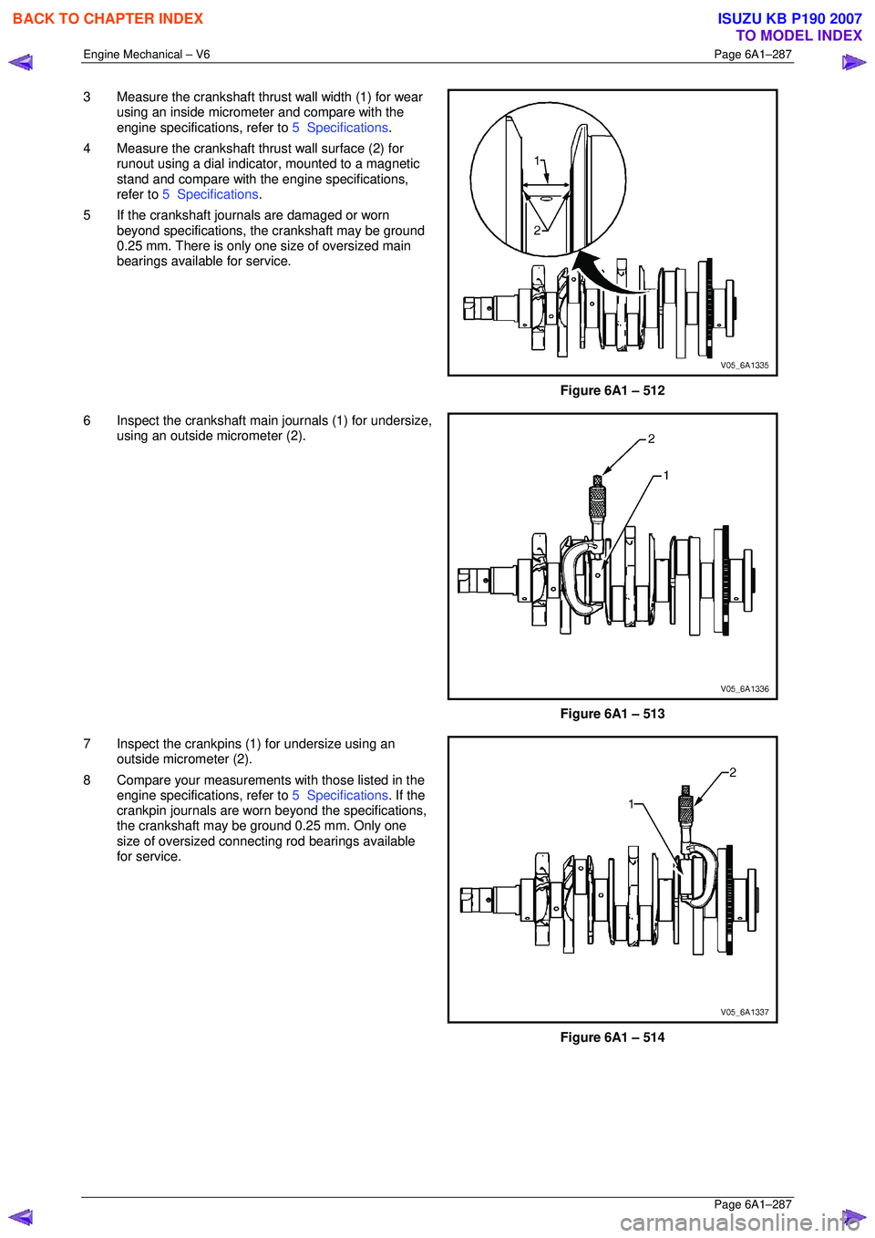
3 Measure the crankshaft thrust wall width (1) for wear
using an inside micrometer and compare with the
engine specifications, refer to 5 Specifications.
4 Measure the crankshaft thrust wall surface (2) for runout using a dial indica tor, mounted to a magnetic
stand and compare with t he engine specifications,
refer to 5 Specifications .
5 If the crankshaft journals are damaged or worn beyond specifications, t he crankshaft may be ground
0.25 mm. There is only one size of oversized main
bearings available for service.
Figure 6A1 – 512
6 Inspect the crankshaft main journals (1) for undersize, using an outside micrometer (2).
Figure 6A1 – 513
7 Inspect the crankpins (1) for undersize using an outside micrometer (2).
8 Compare your measurements with those listed in the
engine specifications, refer to 5 Specifications. If the
crankpin journals are worn beyond the specifications,
the crankshaft may be ground 0.25 mm. Only one
size of oversized connecting rod bearings available
for service.
Figure 6A1 – 514
BACK TO CHAPTER INDEX
TO MODEL INDEX
ISUZU KB P190 2007
Page 3065 of 6020
Engine Mechanical – V6 Page 6A1–288
Page 6A1–288
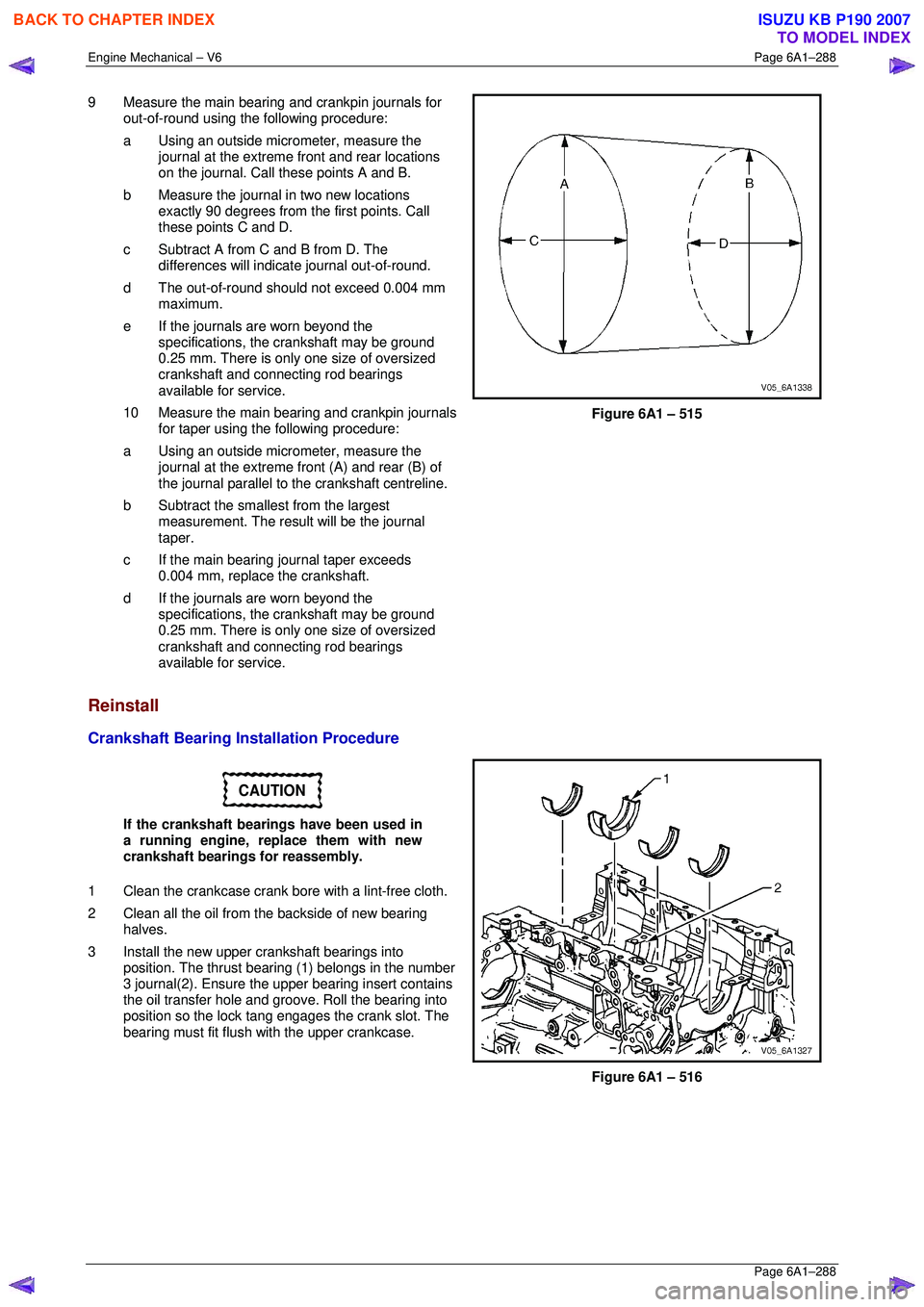
9 Measure the main bearing and crankpin journals for
out-of-round using the following procedure:
a Using an outside micr ometer, measure the
journal at the extreme front and rear locations
on the journal. Call these points A and B.
b Measure the journal in two new locations exactly 90 degrees from the first points. Call
these points C and D.
c Subtract A from C and B from D. The differences will indicate journal out-of-round.
d The out-of-round shoul d not exceed 0.004 mm
maximum.
e If the journals are worn beyond the specifications, the crankshaft may be ground
0.25 mm. There is only one size of oversized
crankshaft and connecting rod bearings
available for service.
10 Measure the main bearing and crankpin journals for taper using the following procedure:
a Using an outside micr ometer, measure the
journal at the extreme fr ont (A) and rear (B) of
the journal parallel to t he crankshaft centreline.
b Subtract the smallest from the largest measurement. The result will be the journal
taper.
c If the main bearing journal taper exceeds 0.004 mm, replace the crankshaft.
d If the journals are worn beyond the specifications, the crankshaft may be ground
0.25 mm. There is only one size of oversized
crankshaft and connecting rod bearings
available for service.
Figure 6A1 – 515
Reinstall
Crankshaft Bearing Installation Procedure
CAUTION
If the crankshaft bearings have been used in
a running engine, replace them with new
crankshaft bearings for reassembly.
1 Clean the crankcase crank bore with a lint-free cloth.
2 Clean all the oil from the backside of new bearing halves.
3 Install the new upper crankshaft bearings into position. The thrust beari ng (1) belongs in the number
3 journal(2). Ensure the upper bearing insert contains
the oil transfer hole and groove. Roll the bearing into
position so the lock tang engages the crank slot. The
bearing must fit flush with the upper crankcase.
Figure 6A1 – 516
BACK TO CHAPTER INDEX
TO MODEL INDEX
ISUZU KB P190 2007
Page 3066 of 6020
Engine Mechanical – V6 Page 6A1–289
Page 6A1–289
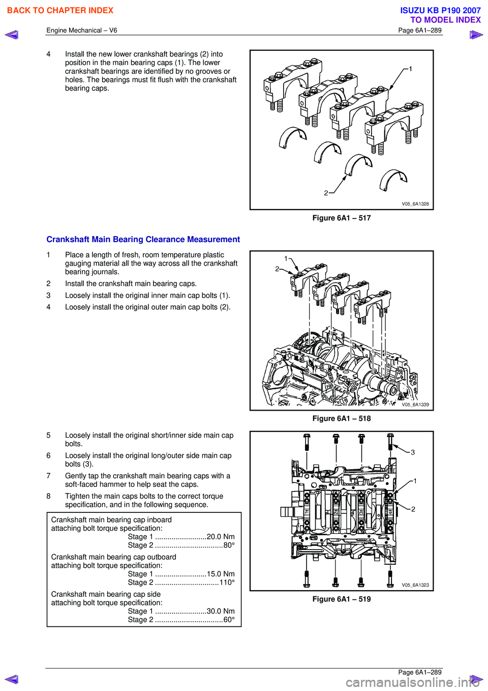
4 Install the new lower crankshaft bearings (2) into
position in the main bearing caps (1). The lower
crankshaft bearings are ident ified by no grooves or
holes. The bearings must fit flush with the crankshaft
bearing caps.
Figure 6A1 – 517
Crankshaft Main Bearing Clearance Measurement
1 Place a length of fresh, room temperature plastic
gauging material all the way across all the crankshaft
bearing journals.
2 Install the crankshaft main bearing caps.
3 Loosely install the original inner main cap bolts (1).
4 Loosely install the original outer main cap bolts (2).
Figure 6A1 – 518
5 Loosely install the original short/inner side main cap bolts.
6 Loosely install the original long/outer side main cap
bolts (3).
7 Gently tap the crankshaft main bearing caps with a soft-faced hammer to help seat the caps.
8 Tighten the main caps bolts to the correct torque specification, and in the following sequence.
Crankshaft main bearing cap inboard
attaching bolt torque specification:
Stage 1 .........................20.0 Nm
Stage 2................................. 80°
Crankshaft main bearing cap outboard
attaching bolt torque specification:
Stage 1 .........................15.0 Nm
Stage 2............................... 110°
Crankshaft main bearing cap side
attaching bolt torque specification:
Stage 1 .........................30.0 Nm
Stage 2................................. 60°
Figure 6A1 – 519
BACK TO CHAPTER INDEX
TO MODEL INDEX
ISUZU KB P190 2007
Page 3067 of 6020
Engine Mechanical – V6 Page 6A1–290
Page 6A1–290
NOTE
Do not rotate the crankshaft.
9 Allow the assembly to sit for 2 minutes.
10 Remove the crankshaft bearing cap side bolts.
11 Remove the crankshaft bearing cap outer bolts (2).
12 Remove the crankshaft bearing cap inner bolts (1).
13 Install the crankshaft main bearing cap remover Tool No. J-41818 as previously described and remove the
crankshaft bearing cap.
14 Repeat steps 10 to 13 for the remaining crankshaft bearing caps.
Figure 6A1 – 520
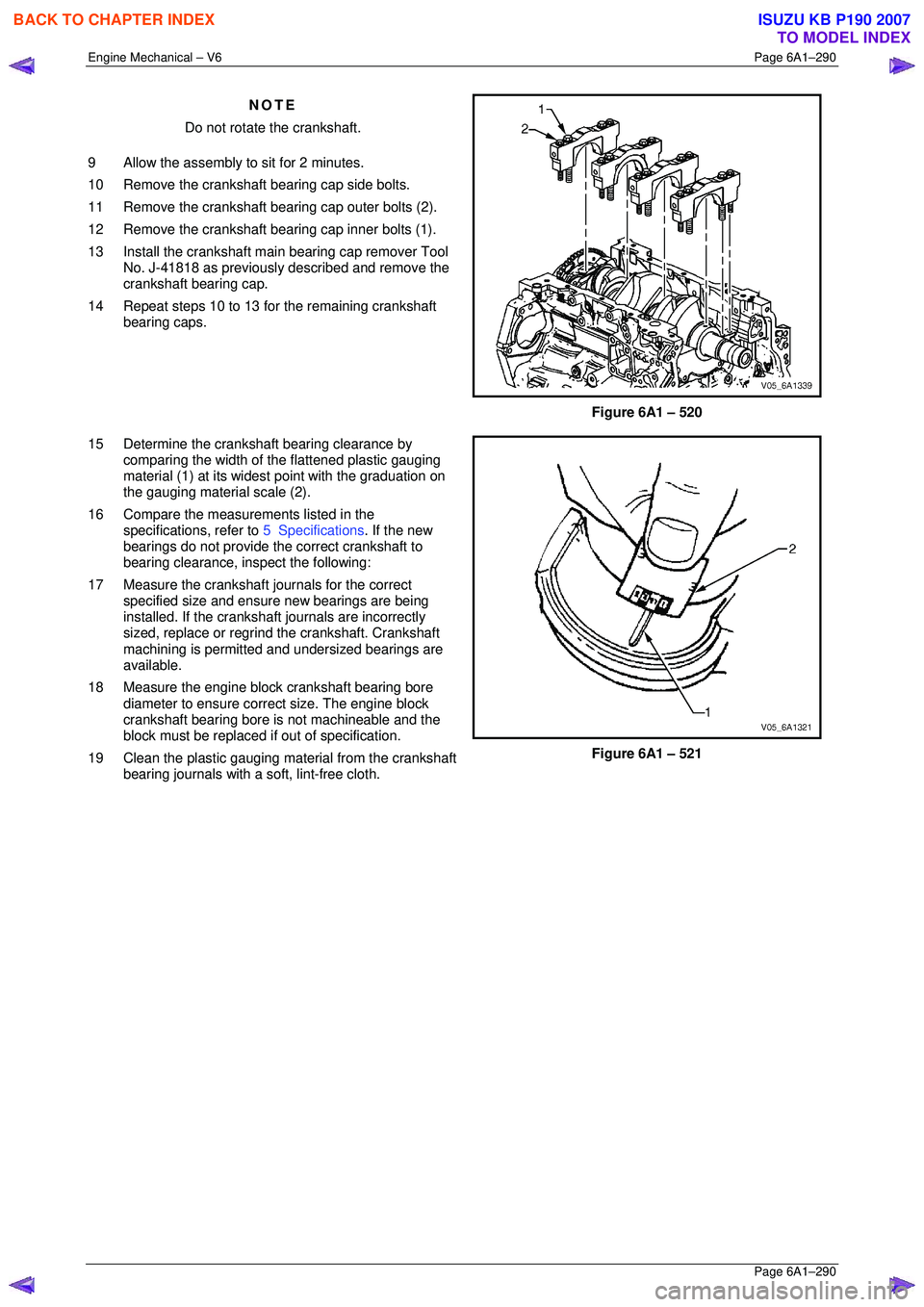
15 Determine the crankshaft bearing clearance by comparing the width of the flattened plastic gauging
material (1) at its widest point with the graduation on
the gauging material scale (2).
16 Compare the measur ements listed in the
specifications, refer to 5 Specifications. If the new
bearings do not provide the correct crankshaft to
bearing clearance, inspect the following:
17 Measure the crankshaft journals for the correct specified size and ensure new bearings are being
installed. If the crankshaft journals are incorrectly
sized, replace or regrind the crankshaft. Crankshaft
machining is permitted and undersized bearings are
available.
18 Measure the engine block crankshaft bearing bore diameter to ensure correct size. The engine block
crankshaft bearing bore is not machineable and the
block must be replaced if out of specification.
19 Clean the plastic gauging material from the crankshaft bearing journals with a soft, lint-free cloth.
Figure 6A1 – 521
BACK TO CHAPTER INDEX
TO MODEL INDEX
ISUZU KB P190 2007
Page 3068 of 6020

Engine Mechanical – V6 Page 6A1–291
Page 6A1–291
Crankshaft Final Installation Procedure
1 If removed, install the crankshaft sprocket drive
pin (1). Lightly tap the pin in place with a small soft
face, bronze/plastic, hammer until it bottoms in the
hole.
Figure 6A1 – 522
CAUTION
Ensure the crankshaft position sensor has
been removed from the cylinder block prior
to loading the crankshaft, as damage to the
sensor may occur.
2 Apply a liberal amount of clean engine oil to the upper and lower bearing surfaces.
3 Gently lower the crankshaft (1) into position in the cylinder block (2).
Figure 6A1 – 523
4 Install the crankshaft main bearing caps.
5 Loosely install the original inner main cap bolts (1).
CAUTION
The outer crankshaft bearing cap bolts (2)
are yield tightened during assembly and
must be replaced prior to reassembly. Outer
crankshaft bearing cap bolts that are not
replaced will not torque to the correct clamp
load and can lead to serious engine damage.
6 Loosely install the new outer main bearing cap bolts (2).
7 Gently tap the crankshaft main bearing caps with a soft-faced hammer to help seat the caps.
Figure 6A1 – 524
BACK TO CHAPTER INDEX
TO MODEL INDEX
ISUZU KB P190 2007
Page 3069 of 6020
Engine Mechanical – V6 Page 6A1–292
Page 6A1–292
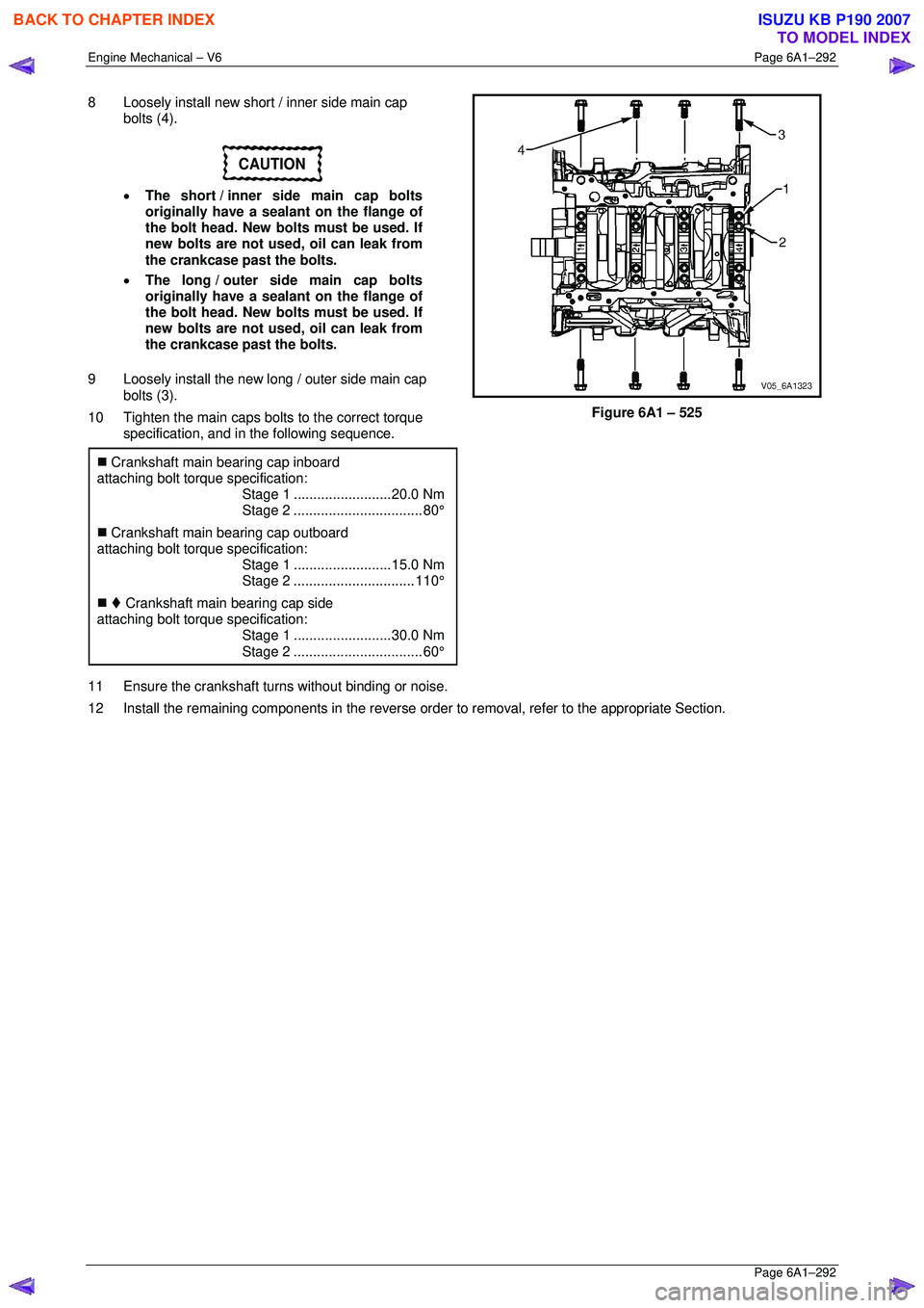
8 Loosely install new short / inner side main cap
bolts (4).
CAUTION
• The short / inner side main cap bolts
originally have a sealant on the flange of
the bolt head. New bolts must be used. If
new bolts are not used, oil can leak from
the crankcase past the bolts.
• The long / outer side main cap bolts
originally have a sealant on the flange of
the bolt head. New bolts must be used. If
new bolts are not used, oil can leak from
the crankcase past the bolts.
9 Loosely install the new long / outer side main cap bolts (3).
10 Tighten the main caps bolts to the correct torque specification, and in the following sequence.
�„ Crankshaft main bearing cap inboard
attaching bolt torque specification:
Stage 1 .........................20.0 Nm
Stage 2................................. 80°
�„ Crankshaft main bearing cap outboard
attaching bolt torque specification:
Stage 1 .........................15.0 Nm
Stage 2............................... 110°
�„ Crankshaft main bearing cap side
attaching bolt torque specification:
Stage 1 .........................30.0 Nm
Stage 2................................. 60°
Figure 6A1 – 525
11 Ensure the crankshaft turns without binding or noise.
12 Install the remaining components in the reverse order to removal, refer to the appropriate Section.
BACK TO CHAPTER INDEX
TO MODEL INDEX
ISUZU KB P190 2007
Page 3070 of 6020
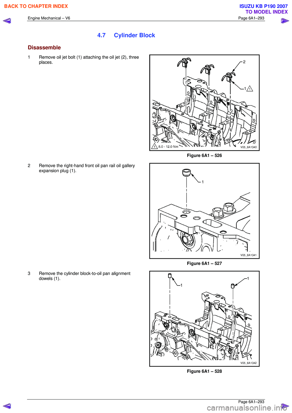
Engine Mechanical – V6 Page 6A1–293
Page 6A1–293
4.7 Cylinder Block
Disassemble
1 Remove oil jet bolt (1) attaching the oil jet (2), three
places.
Figure 6A1 – 526
2 Remove the right-hand front oil pan rail oil gallery expansion plug (1).
Figure 6A1 – 527
3 Remove the cylinder block-to-oil pan alignment dowels (1).
Figure 6A1 – 528
BACK TO CHAPTER INDEX
TO MODEL INDEX
ISUZU KB P190 2007