ISUZU KB P190 2007 Workshop Repair Manual
Manufacturer: ISUZU, Model Year: 2007, Model line: KB P190, Model: ISUZU KB P190 2007Pages: 6020, PDF Size: 70.23 MB
Page 3051 of 6020
Engine Mechanical – V6 Page 6A1–274
Page 6A1–274
Reassemble
Piston and Piston Pin
CAUTION
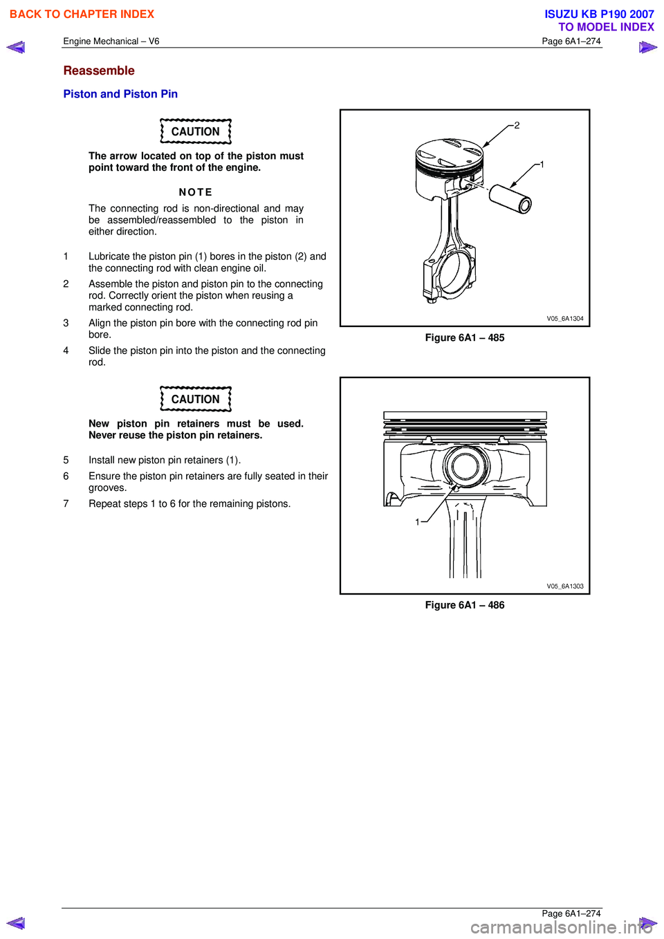
The arrow located on top of the piston must
point toward the front of the engine.
NOTE
The connecting rod is non-directional and may
be assembled/reassembled to the piston in
either direction.
1 Lubricate the piston pin (1) bores in the piston (2) and
the connecting rod with clean engine oil.
2 Assemble the piston and piston pin to the connecting rod. Correctly orient the piston when reusing a
marked connecting rod.
3 Align the piston pin bore with the connecting rod pin
bore.
4 Slide the piston pin into the piston and the connecting
rod.
Figure 6A1 – 485
CAUTION
New piston pin retainers must be used.
Never reuse the piston pin retainers.
5 Install new piston pin retainers (1).
6 Ensure the piston pin retainers are fully seated in their grooves.
7 Repeat steps 1 to 6 for the remaining pistons.
Figure 6A1 – 486
BACK TO CHAPTER INDEX
TO MODEL INDEX
ISUZU KB P190 2007
Page 3052 of 6020
Engine Mechanical – V6 Page 6A1–275
Page 6A1–275
Piston Ring
NOTE
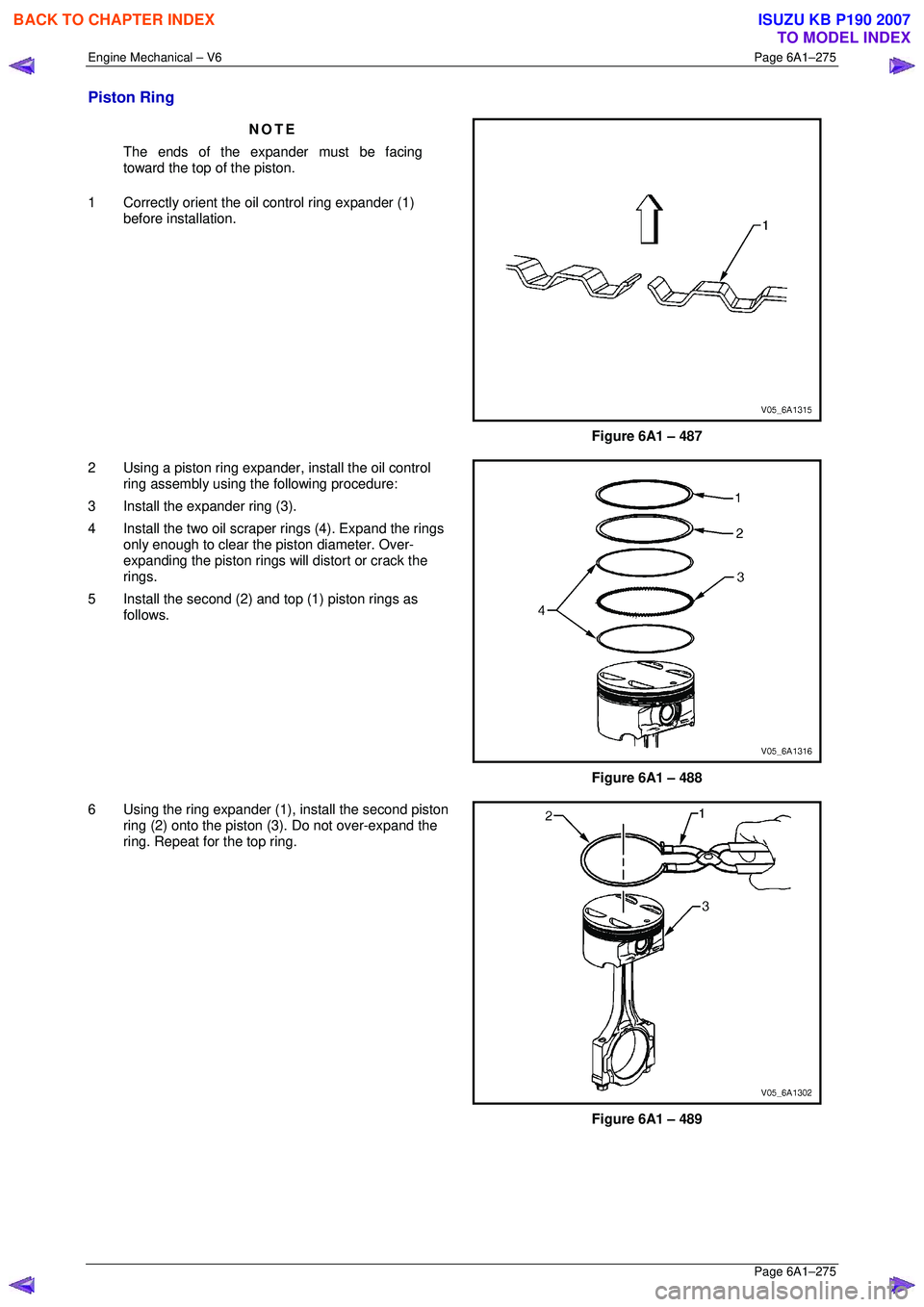
The ends of the expander must be facing
toward the top of the piston.
1 Correctly orient the oil control ring expander (1) before installation.
Figure 6A1 – 487
2 Using a piston ring expander, install the oil control
ring assembly using the following procedure:
3 Install the expander ring (3).
4 Install the two oil scraper rings (4). Expand the rings only enough to clear the piston diameter. Over-
expanding the piston rings w ill distort or crack the
rings.
5 Install the second (2) and top (1) piston rings as follows.
Figure 6A1 – 488
6 Using the ring expander (1), install the second piston
ring (2) onto the piston (3). Do not over-expand the
ring. Repeat for the top ring.
Figure 6A1 – 489
BACK TO CHAPTER INDEX
TO MODEL INDEX
ISUZU KB P190 2007
Page 3053 of 6020
Engine Mechanical – V6 Page 6A1–276
Page 6A1–276
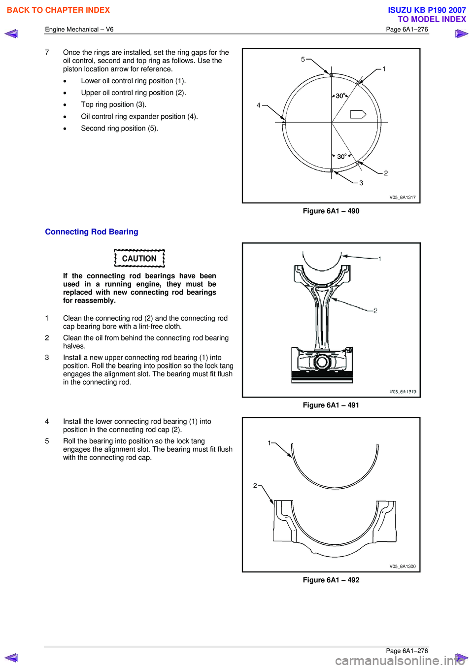
7 Once the rings are installed, set the ring gaps for the
oil control, second and top ring as follows. Use the
piston location arrow for reference.
• Lower oil control ring position (1).
• Upper oil control ring position (2).
• Top ring position (3).
• Oil control ring ex pander position (4).
• Second ring position (5).
Figure 6A1 – 490
Connecting Rod Bearing
CAUTION
If the connecting rod bearings have been
used in a running engine, they must be
replaced with new connecting rod bearings
for reassembly.
1 Clean the connecting rod (2) and the connecting rod
cap bearing bore with a lint-free cloth.
2 Clean the oil from behind the connecting rod bearing halves.
3 Install a new upper connecting rod bearing (1) into position. Roll the bearing into position so the lock tang
engages the alignment slot. The bearing must fit flush
in the connecting rod.
Figure 6A1 – 491
4 Install the lower connecting rod bearing (1) into position in the connecting rod cap (2).
5 Roll the bearing into position so the lock tang engages the alignment slot. The bearing must fit flush
with the connecting rod cap.
Figure 6A1 – 492
BACK TO CHAPTER INDEX
TO MODEL INDEX
ISUZU KB P190 2007
Page 3054 of 6020
Engine Mechanical – V6 Page 6A1–277
Page 6A1–277
Reinstall
Piston Connecting Rod and Connecting Rod Bearing Installation
CAUTION
The piston is directional and must be
installed in the engine block in the correct
direction. The locating arrow on the top of
each piston must be pointing toward the
front of the engine.
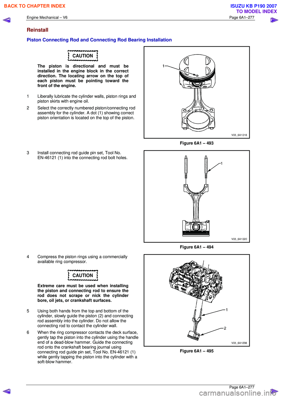
1 Liberally lubricate the cy linder walls, piston rings and
piston skirts with engine oil.
2 Select the correctly numbered piston/connecting rod
assembly for the cylinder. A dot (1) showing correct
piston orientation is locat ed on the top of the piston.
Figure 6A1 – 493
3 Install connecting rod guide pin set, Tool No. EN-46121 (1) into the connecting rod bolt holes.
Figure 6A1 – 494
4 Compress the piston rings using a commercially available ring compressor.
CAUTION
Extreme care must be used when installing
the piston and connecting rod to ensure the
rod does not scrape or nick the cylinder
bore, oil jets, or crankshaft surfaces.
5 Using both hands from the top and bottom of the cylinder, slowly guide the piston (2) and connecting
rod assembly into the cylinder. Do not allow the
connecting rod to contact the cylinder wall.
6 When the ring compressor c ontacts the deck surface,
gently tap the piston into the cylinder using the handle
end of a dead-blow hammer. Guide the connecting
rod onto the crankshaft bearing journal using
connecting rod guide pin set, Tool No. EN-46121 (1)
while gently tapping the piston into the cylinder with a
soft-blow hammer.
Figure 6A1 – 495
BACK TO CHAPTER INDEX
TO MODEL INDEX
ISUZU KB P190 2007
Page 3055 of 6020
Engine Mechanical – V6 Page 6A1–278
Page 6A1–278
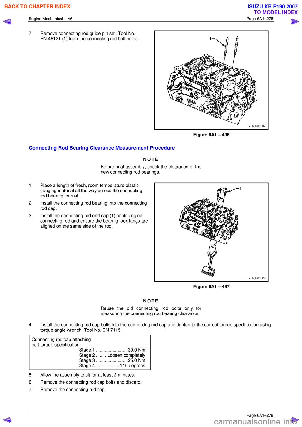
7 Remove connecting rod guide pin set, Tool No.
EN-46121 (1) from the connecting rod bolt holes.
Figure 6A1 – 496
Connecting Rod Bearing Clearance Measurement Procedure
NOTE
Before final assembly, check the clearance of the
new connecting rod bearings.
1 Place a length of fresh, room temperature plastic
gauging material all the way across the connecting
rod bearing journal.
2 Install the connecting rod bearing into the connecting
rod cap.
3 Install the connecting rod end cap (1) on its original
connecting rod and ensure t he bearing lock tangs are
aligned on the same side of the rod.
Figure 6A1 – 497
NOTE
Reuse the old connecting rod bolts only for
measuring the connecting rod bearing clearance.
4 Install the connecting rod cap bolts in to the connecting rod cap and tighten to the correct torque specification using
torque angle wrench, Tool No. EN-7115.
Connecting rod cap attaching
bolt torque specification:
Stage 1 .........................30.0 Nm
Stage 2 ........Loosen completely
Stage 3 .........................25.0 Nm
Stage 4 ..................110 degrees
5 Allow the assembly to sit for at least 2 minutes.
6 Remove the connecting rod cap bolts and discard.
7 Remove the connecting rod cap.
BACK TO CHAPTER INDEX
TO MODEL INDEX
ISUZU KB P190 2007
Page 3056 of 6020
Engine Mechanical – V6 Page 6A1–279
Page 6A1–279
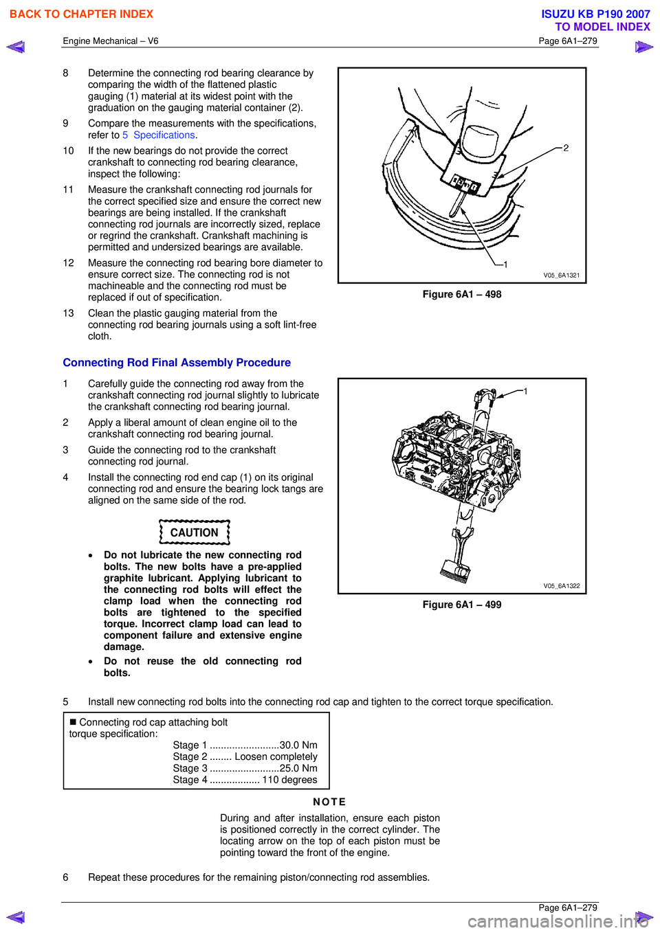
8 Determine the connecting rod bearing clearance by
comparing the width of the flattened plastic
gauging (1) material at its widest point with the
graduation on the gauging mate rial container (2).
9 Compare the measurements with the specifications,
refer to 5 Specifications .
10 If the new bearings do not provide the correct crankshaft to connecting rod bearing clearance,
inspect the following:
11 Measure the crankshaft connecting rod journals for the correct specified size and ensure the correct new
bearings are being installed. If the crankshaft
connecting rod journals are in correctly sized, replace
or regrind the crankshaft. Crankshaft machining is
permitted and undersized bearings are available.
12 Measure the connecting rod bearing bore diameter to
ensure correct size. The connecting rod is not
machineable and the connecting rod must be
replaced if out of specification.
13 Clean the plastic gauging material from the connecting rod bearing journals using a soft lint-free
cloth.
Figure 6A1 – 498
Connecting Rod Final Assembly Procedure
1 Carefully guide the connecting rod away from the crankshaft connecting rod journal slightly to lubricate
the crankshaft connecting rod bearing journal.
2 Apply a liberal amount of clean engine oil to the crankshaft connecting rod bearing journal.
3 Guide the connecting rod to the crankshaft connecting rod journal.
4 Install the connecting rod end cap (1) on its original
connecting rod and ensure t he bearing lock tangs are
aligned on the same side of the rod.
CAUTION
• Do not lubricate the new connecting rod
bolts. The new bolts have a pre-applied
graphite lubricant. Applying lubricant to
the connecting rod bolts will effect the
clamp load when the connecting rod
bolts are tightened to the specified
torque. Incorrect clamp load can lead to
component failure and extensive engine
damage.
• Do not reuse the old connecting rod
bolts.
Figure 6A1 – 499
5 Install new connecting rod bolts into the connecting r od cap and tighten to the correct torque specification.
�„ Connecting rod cap attaching bolt
torque specification:
Stage 1 .........................30.0 Nm
Stage 2 ........Loosen completely
Stage 3 .........................25.0 Nm
Stage 4 ..................110 degrees
NOTE
During and after installation, ensure each piston
is positioned correctly in the correct cylinder. The
locating arrow on the top of each piston must be
pointing toward the front of the engine.
6 Repeat these procedures for the rema ining piston/connecting rod assemblies.
BACK TO CHAPTER INDEX
TO MODEL INDEX
ISUZU KB P190 2007
Page 3057 of 6020
Engine Mechanical – V6 Page 6A1–280
Page 6A1–280
7 Reinstall the oil pan and oil pump pick up assembly, refer to 4.2 Oil Pan and Oil Pump Suction Pipe Assembly.
8 Reinstall the cylinder heads, refer to 3.22 Cylinder Head Assembly.
9 Reinstall the engine assembly, refer to 4.1 Engine .
BACK TO CHAPTER INDEX
TO MODEL INDEX
ISUZU KB P190 2007
Page 3058 of 6020
Engine Mechanical – V6 Page 6A1–281
Page 6A1–281
4.6 Crankshaft and Main Bearings
1 Remove the engine assembly, refer to 4.1 Engine .
2 Remove both cylinder head assemblies, refer to 3.22 Cylinder Head Assembly.
3 Remove the oil pan assembly, refer to 4.2 Oil Pan and Oil Pump Suction Pipe Assembly .
4 Remove the piston and connecting rod assemblies, refer to 4.5 Pistons, Pins, Rings, Connecting Rods and Big-
end Bearings .
5 Remove the oil pump assembly, refer to 3.17 Oil Pump Assembly.
6 Remove the crankshaft rear oil seal and plate assembly, refer to 4.4 Crankshaft Rear Seal and Plate Assembly .
7 Remove the crankshaft position sensor, refer to Section 6C1-3 Engine Management – V6 – Service Operations.
Crankshaft End Play Measurement
1 Place a dial indicator at the end of the crankshaft nose.
2 Gently force the crankshaft towards the front and rear of the cylinder block with a lever while monitoring the
movement of the dial indicator.
3 The crankshaft endplay should not exceed specifications, refer to 5 Specifications.
4 If the specifications are ex ceeded, inspect the thrust bearing thrust outer diameter and the crankshaft thrust wall for
wear and/or excessive runout. Compare the va lues with the specifications, refer to 5 Specifications.
5 Replace the thrust bearing or crankshaft as required.
Remove
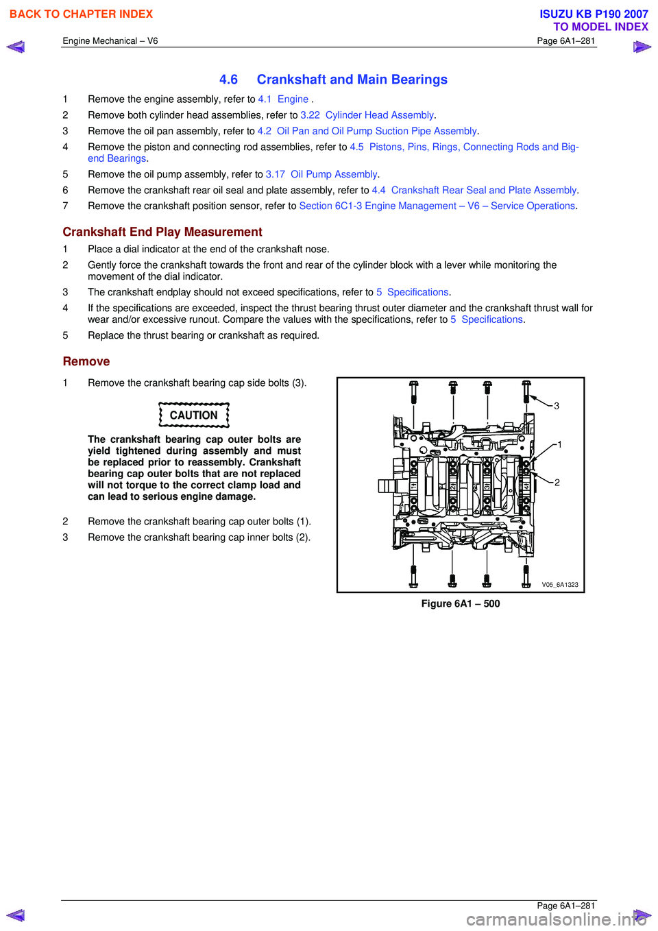
1 Remove the crankshaft bearing cap side bolts (3).
CAUTION
The crankshaft bearing cap outer bolts are
yield tightened during assembly and must
be replaced prior to reassembly. Crankshaft
bearing cap outer bolts that are not replaced
will not torque to the correct clamp load and
can lead to serious engine damage.
2 Remove the crankshaft bearing cap outer bolts (1).
3 Remove the crankshaft bearing cap inner bolts (2).
Figure 6A1 – 500
BACK TO CHAPTER INDEX
TO MODEL INDEX
ISUZU KB P190 2007
Page 3059 of 6020
Engine Mechanical – V6 Page 6A1–282
Page 6A1–282
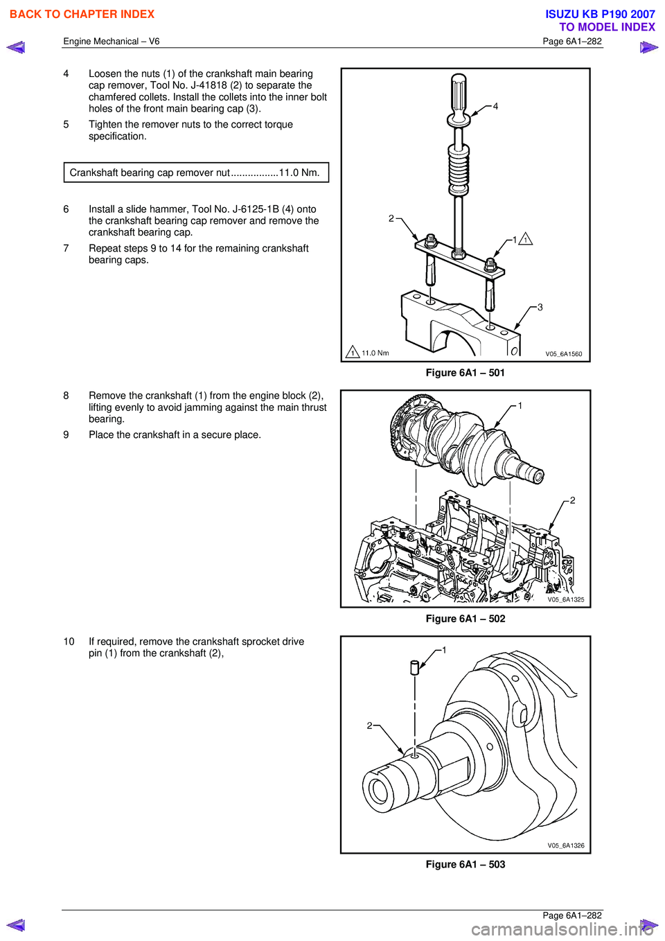
4 Loosen the nuts (1) of the crankshaft main bearing
cap remover, Tool No. J-41818 (2) to separate the
chamfered collets. Install the collets into the inner bolt
holes of the front main bearing cap (3).
5 Tighten the remover nuts to the correct torque specification.
Crankshaft bearing cap remover nut.................11.0 Nm.
6 Install a slide hammer, Tool No. J-6125-1B (4) onto the crankshaft bearing cap remover and remove the
crankshaft bearing cap.
7 Repeat steps 9 to 14 for the remaining crankshaft bearing caps.
Figure 6A1 – 501
8 Remove the crankshaft (1) from the engine block (2), lifting evenly to avoid jamming against the main thrust
bearing.
9 Place the crankshaft in a secure place.
Figure 6A1 – 502
10 If required, remove the crankshaft sprocket drive pin (1) from the crankshaft (2),
Figure 6A1 – 503
BACK TO CHAPTER INDEX
TO MODEL INDEX
ISUZU KB P190 2007
Page 3060 of 6020
Engine Mechanical – V6 Page 6A1–283
Page 6A1–283
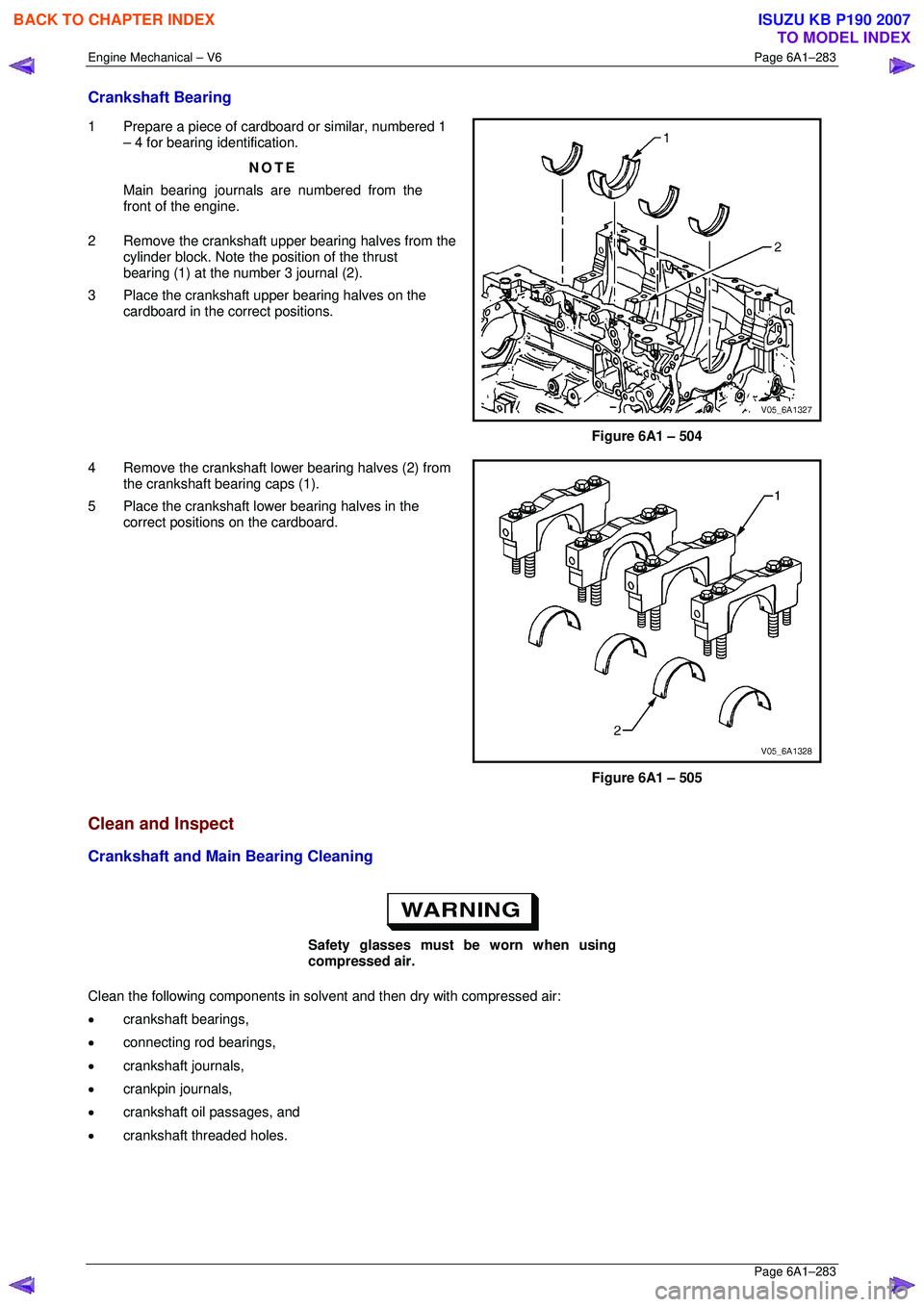
Crankshaft Bearing
1 Prepare a piece of cardboard or similar, numbered 1
– 4 for bearing identification.
NOTE
Main bearing journals are numbered from the
front of the engine.
2 Remove the crankshaft upper bearing halves from the cylinder block. Note the position of the thrust
bearing (1) at the number 3 journal (2).
3 Place the crankshaft upper bearing halves on the cardboard in the correct positions.
Figure 6A1 – 504
4 Remove the crankshaft lower bearing halves (2) from the crankshaft bearing caps (1).
5 Place the crankshaft lower bearing halves in the correct positions on the cardboard.
Figure 6A1 – 505
Clean and Inspect
Crankshaft and Main Bearing Cleaning
Safety glasses must be worn when using
compressed air.
Clean the following components in solvent and then dry with compressed air:
• crankshaft bearings,
• connecting rod bearings,
• crankshaft journals,
• crankpin journals,
• crankshaft oil passages, and
• crankshaft threaded holes.
BACK TO CHAPTER INDEX
TO MODEL INDEX
ISUZU KB P190 2007