ISUZU KB P190 2007 Workshop Repair Manual
Manufacturer: ISUZU, Model Year: 2007, Model line: KB P190, Model: ISUZU KB P190 2007Pages: 6020, PDF Size: 70.23 MB
Page 3681 of 6020

Powertrain Interface Module – V6 Page 6E1–20
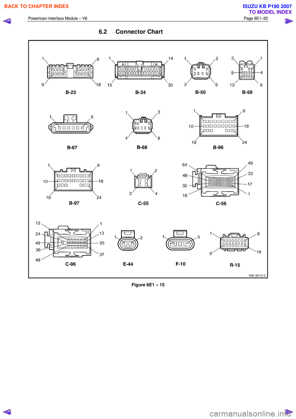
6.2 Connector Chart
Figure 6E1 – 15
BACK TO CHAPTER INDEX
TO MODEL INDEX
ISUZU KB P190 2007
Page 3682 of 6020

Powertrain Interface Module – V6 Page 6E1–21
6.3 Connector Information
PIM Connector Pin Specifications
Pin Description – Connector B-96
Figure 6E1 – 1
Pin No. Wire Colour Circuit
Description Function
1 P/W
A/T 3 Srt W rg
Lmp Auto Transmission 3rd Start W arning Lamp
2 P
A/T Pwr Dr
W rg Lmp Auto Transmission Power Drive W arning Lamp
3 O/L A/T Oil Tmp
W rg Lmp Auto Transmission Oil Temperature W arning Lamp
4 G/Y
Cru Set W rg
Lmp Cruise Set W arning Lamp
5
O/L SVS W rg Lmp Service Vehicle Soon W arning Lamp
6 W Eng Oil W rg
Lmp Engine Oil Pressure W arning Lamp holidays
7
W /L Batt W rg Lmp Battery Charge W arning Lamp
8 Y/B Eng Tmp Gau Engine Coolant Gauge
9 B/R Tac Gau Tacho Gauge – RW D/4W D (2-4) Control
10 W Imob Sig Immobiliser
11 — — Not Connected
12 — — Not Connected
13 L Sft Sel Pos D Shift Selector Position D
14 R/B Sft Sel Pos N Shift Selector Position N
15 R/Y Sft Sel Pos R Shift Selector Position R
16 Y/V Sft Sel Pos P Shift Selector Position P
17 — — Not Connected
18 G/Y A/T Chk W rg
Lmp Auto Transmission Check W arning Lamp
19 — — Not
Connected
20 — — Not Connected
BACK TO CHAPTER INDEX
TO MODEL INDEX
ISUZU KB P190 2007
Page 3683 of 6020

Powertrain Interface Module – V6 Page 6E1–22
Pin No. Wire Colour Circuit
Description Function
21 — — Not
Connected
22 P/L Sft Sel Pos L Shift Selector PRNDL Position L
23 P/B Sft Sel Pos 2 Shift Selector Position 2
24 B/G Sft Sel Pos 3 Shift Selector Position 3
Pin Description – Connector B-97
Figure 6E1 – 2
Pin No. Wire Colour Circuit
Description Function
1
L TOSS Sen IND Speed Sensor
2 L/W Lat G Sen Lateral G-sensor
3 O Lat G Sen Lateral G-sensor
4 B Lat G Sen Lateral G-sensor
5 — — Not Connected
6 — — Not Connected
7 — — Not Connected
8 — — Not Connected
9 — — Not Connected
10 G/W A/T 3 Srt Sw Auto Transmission 3rd Start Switch
11 G/R Thermo AMP Thermo AMP
12 L/W 2-4 Cont RW D/4W D (2-4) Control
13 G/W Cru Cont ON
Lmp Cruise Control ON Lamp
14 W /G
Cru Cont Main
Sw Cruise Control Main Switch
15 LG Cru Cont Set
Sw Cruise Control Set Switch
16 BR/Y
Cru Cont Res
Sw Cruise Control Resume Switch
17 GR/G
Cru Cont Can
Sw Cruise Control Cancel Switch
18
B/W TOSS Sen IND Speed Sensor
19 — — Not Connected
BACK TO CHAPTER INDEX
TO MODEL INDEX
ISUZU KB P190 2007
Page 3684 of 6020

Powertrain Interface Module – V6 Page 6E1–23
Pin No. Wire Colour Circuit
Description Function
20 P/L
Cru Cont Sw
Pwr ON Cruise Control Switch Power ON
21 BR/R Batt Battery
Supply
22 B Grd Ground Engine Bay – L/H
23 — — Not Connected
24 G/Y A/T Pwr Dr Sw Auto Transmission Power Drive
BACK TO CHAPTER INDEX
TO MODEL INDEX
ISUZU KB P190 2007
Page 3685 of 6020

Powertrain Interface Module – V6 Page 6E1–24
7 Diagnostics Starting Point
7.1 Diagnostic Requirements, Precautions
and Preliminary Checks
Basic Knowledge Required
A lack of basic understanding of electronics,
electrical wiring circuits and use of electrical
circuit testing tools when performing the PIM
diagnostic procedures could result in
incorrect diagnostic results or damage to
components.
In addition, understanding of the Engine Management System is essential to prevent misdiagnosis and component
damage. Refer to 6C1-1 Engine Management – V6 – General Information.
Basic Diagnostic Tools Required
Use of incorrect electrical circuit diagnostic
tools when performing the PIM diagnostic
procedures could result in incorrect
diagnostic results or damage to components.
The following electrical circuit testing tools are required to perform the diagnostic procedures detailed in this Section:
• Tech 2.
• Test lamp, refer to 8A Electrical - Body and Chassis for further information.
• Digital multimeter with 10 M Ω impedance, refer to 8A Electrical - Body and Chassis for further information.
• Connector test adapter kit Tool No. J35616-A.
Diagnostic Precautions
In addition to the safety and precautionary
measures listed in 11.1 Safety and
Precautionary Measures, the following
diagnostic precautions must be observed
when performing any PIM diagnostic
procedure:
• Use only the test equipment specified in the diagnostic tables. Other test equipment may either give incorrect
results or damage serviceable components.
• Do not clear any DTCs unless instructed.
• The fault must be present when using the DTC Diagnostic Tables. Otherwise, misdiagnosis or replacement of
serviceable parts may occur.
• Always use connector adapters such as those contained in connector test adapter kit Tool No. J35616-A to prevent
connector terminal damage.
BACK TO CHAPTER INDEX
TO MODEL INDEX
ISUZU KB P190 2007
Page 3686 of 6020

Powertrain Interface Module – V6 Page 6E1–25
• Thorough inspection of the wiring circuits and connectors listed in the diagnostic procedures must be performed,
otherwise misdiagnosis may occur.
• Inspect the electrical circuitry or connector terminals that are suspected to be causing the complaint for the
following conditions:
• backed-out connector terminals,
• improper wiring connector mating,
• broken wiring connector locks,
• damaged connector terminals, and
• physical damage to the wiring harness.
• Before replacing a component, inspect its connector terminal for corrosion or deformation that may cause the fault
condition.
Preliminary Checks
The PIM preliminary check examines easily accessible components which may cause problems with the PIM. This visual
and physical inspection procedure may quickly identify the fault condition and eliminate the need for additional diagnosis.
• Refer to Service Techlines for relevant information regarding the fault condition.
• Ensure the battery is fully charged.
• Check the battery connections for corrosion or a loose terminal.
• Perform a visual and physical inspection of the following:
• PIM component wiring harness and terminals for proper connections, pinches or cuts, and
• PIM wiring harness routing which may be positioned very close to a high voltage or high current devices such
as aftermarket audio systems.
NOTE
High voltage or high current devices may induce
electrical noise on a circuit, which can interfere
with normal circuit operation.
• The PIM is sensitive to Electro Magnetic Interference (EMI). Check for incorrect aftermarket theft deterrent
devices, lights or mobile phone installations if an intermittent malfunction is suspected.
7.2 Diagnostic System Check
Step Action Yes No
1
Have you met the basic diagnostic requirements listed in the PIM
Diagnostic Starting Point?
Go to Step 2 Refer to
7.1 Diagnostic
Requirements,
Precautions and
Preliminary Checks
2 Have you read the Diagnostic Precautions?
Go to Step 3 Refer to
7.1 Diagnostic Requirements,
Precautions and
Preliminary Checks
3 Have you performed the Preliminary Checks?
Go to Step 4 Refer to
7.1 Diagnostic Requirements,
Precautions and
Preliminary Checks
BACK TO CHAPTER INDEX
TO MODEL INDEX
ISUZU KB P190 2007
Page 3687 of 6020

Powertrain Interface Module – V6 Page 6E1–26
Step Action Yes No
4
Using Tech 2, attempt to communicate with the PIM.
Does Tech 2 communicate with the PIM? Go to Step 5 Refer to
7.3 Powertrain Interface Module –
Module
Communication Check Failure
Diagnostic Table
5 Using Tech 2, view and record all DTCs.
Does Tech 2 display any DTCs? Go to Step 6 Refer to
Intermittent Fault Conditions.
6 Does DTC C0550 fail this ignition cycle? Refer to
9.1 DTC
C0550 – PIM
Internal Fault
Diagnostic Table Go to Step 7
7 Does DTC U2100 fail this ignition cycle? Refer to
9.2 DTC
U2100 – No
Communication
W ith CAN Bus (High Speed) Diagnostic
Table Go to Step 8
8 Does DTC U2106 fail this ignition cycle? Refer to
9.4 DTC
U2106 – CAN Bus
No Communication
W ith Transmission Control Module Go to Step 9
9
Does DTC U2105 fail this ignition cycle? Refer to
9.3 DTC
U2105 – CAN Bus
No Communication
W ith Engine Control Module Diagnostic
Table Go to Step 10
10 Does Tech 2 display multiple DTCs? Refer to
the DTC Table of
the fault condition
that is most likely to
trigger multiple
DTCs. Refer to
4.1 Diagnostic General
Descriptions for information on
multiple DTCs fault condition Refer to the relevant
DTC table
When all diagnosis and repairs are completed, clear all DTCs and check the system for correct operation.
BACK TO CHAPTER INDEX
TO MODEL INDEX
ISUZU KB P190 2007
Page 3688 of 6020

Powertrain Interface Module – V6 Page 6E1–27
7.3 Powertrain Interface Module – Module
Communication Check Failure
Diagnostic Table
Step Action Yes No
1
Has the Diagnostic System Check been performed?
Go to Step 2 Refer to
7.2 Diagnostic System Check
2 Test the following PIM circuits for a high resistance, open circuit or
short to ground fault condition. Refer to 8A Electrical - Body and
Chassis for information on electrical diagnosis:
• 12 V battery supply circuit,
• 12 V ignition circuit, and
• ground circuit.
Has any fault been found and rectified? Go to Step 10 Go to Step 3
3 1 Disconnect the ECM harness connector.
2 Switch off the ignition for 10 seconds.
3 Using Tech 2, attempt to communicate with the PIM.
NOTE
Other DTCs may set when the ECM connector is
disconnected and the ignition is switched on. Disregard
DTCs that set under this condition on this DTC Table.
Does Tech 2 communicate with the PIM? Go to Step 4 For vehicles with
automatic
transmissions, go to
Step 5. For vehicles with manual
transmission go to Step 8
4 Replace the ECM. Refer to 6C1-3 Engine Management – V6 –
Service Operations.
Has the repair been completed? Go to Step 10 —
5 1 Disconnect the TCM harness connector.
2 Switch off the ignition for 10 seconds.
3 Using Tech 2, attempt to communicate with the PIM.
Does Tech 2 communicate with the PIM? Go to Step 6 Go to Step 8
6 Test serial data circuits between the TCM and ECM for a short to
voltage, short to ground or short together condition.
Has any fault been found and rectified? Go to Step 10 Go to Step 7
7 Replace the TCM. Refer to 7C4 Automatic Transmission – 4L60E –
On-vehicle Servicing.
Has the repair been completed? Go to Step 10 —
8 Test serial data circuits between the PIM and ECM for vehicles with
manual transmission, or between the PIM and TCM for vehicles with
automatic transmission for a high resistance or open circuit fault
condition. Refer to 8A Electrical - Body and Chassis for information on
wiring circuit testing and repair.
Has any fault been found and rectified? Go to Step 10 Go to Step 9
9 Replace the PIM. Refer to 11.2 Powertrain Interface Module.
Has the repair been completed? Go to Step 10 —
10 Using Tech 2, attempt to communicate with the PIM.
Does Tech 2 communicate with the PIM? Go to Step 11 Refer to
7.2 Diagnostic System Check
BACK TO CHAPTER INDEX
TO MODEL INDEX
ISUZU KB P190 2007
Page 3689 of 6020

Powertrain Interface Module – V6 Page 6E1–28
Step Action Yes No
11
1 Using Tech 2, clear all DTCs.
2 Switch off the ignition for 30 seconds.
3 Check for DTCs.
Does Tech 2 display any PIM DTCs? Refer to
7.2 Diagnostic System Check Go to Step 7
12
Does Tech 2 display any other DTCs? Refer to the
appropriate Section System OK
When all diagnosis and repairs are completed, clear all DTCs and check the system for correct operation.
BACK TO CHAPTER INDEX
TO MODEL INDEX
ISUZU KB P190 2007
Page 3690 of 6020

Powertrain Interface Module – V6 Page 6E1–29
Intermittent Fault Conditions
8.1 Intermittent Conditions Diagnostic Table
Description
A fault condition is intermittent if one of the following conditions exists:
• The fault condition is not always present.
• The fault condition cannot be presently duplicated.
• There is no Current DTC but a History DTC is stored.
Diagnostic Table
Checks Actions
Preliminary
• Perform the Preliminary Checks, refer to 7.1 Diagnostic Requirements,
Precautions and Preliminary Checks.
• Gather information from the customer regarding the conditions that trigger the
intermittent fault such as:
• At what engine or ambient temperature range does the fault occur?
• Does the fault occur when operating aftermarket electrical equipment inside
the vehicle?
• Does the fault occur on rough roads or in wet road conditions?
• If the intermittent fault is a start and then stall condition, check immobiliser system.
Refer to 11A Immobiliser.
Harness / Connector Install Tech 2 and perform the Tech 2 Intermittent Fault Tests. Refer to 4.1 Diagnostic General Descriptions for information on Tech 2 ECU diagnostic
tests.
W arning Indicator The following conditions may cause an intermittent Malfunction Indicator Lamp fault with
no DTC listed:
• Electromagnetic Interference (EMI) caused by a faulty relay, ECM controlled
solenoid, switch or other external source.
• Incorrect installation of aftermarket electrical equipment such as the following:
• mobile phones,
• theft deterrent alarms,
• lights, or
• radio equipment.
• Loose PIM ground connections.
BACK TO CHAPTER INDEX
TO MODEL INDEX
ISUZU KB P190 2007